


Video Intercom Demo Case
User Manual

Video Intercom Demo Case·User Manual
i
Quick Start Guide
© 2019 Hangzhou Hikvision Digital Technology Co., Ltd.
This user manual is intended for users of the video intercom demo case.
About this Manual
This Manual is subject to domestic and international copyright protection. Hangzhou
Hikvision Digital Technology Co., Ltd. (“Hikvision”) reserves all rights to this manual. This
manual cannot be reproduced, changed, translated, or distributed, partially or wholly, by
any means, without the prior written permission of Hikvision.
Trademarks
and other Hikvision marks are the property of Hikvision and are
registered trademarks or the subject of applications for the same by Hikvision and/or its
affiliates. Other trademarks mentioned in this manual are the properties of their
respective owners. No right of license is given to use such trademarks without express
permission.
Disclaimer
TO THE MAXIMUM EXTENT PERMITTED BY APPLICABLE LAW, HIKVISION MAKES NO WARRANTIES,
EXPRESS OR IMPLIED, INCLUDING WITHOUT LIMITATION THE IMPLIED WARRANTIES OF
MERCHANTABILITY AND FITNESS FOR A PARTICULAR PURPOSE, REGARDING THIS MANUAL.
HIKVISION DOES NOT WARRANT, GUARANTEE, OR MAKE ANY REPRESENTATIONS REGARDING THE
USE OF THE MANUAL, OR THE CORRECTNESS, ACCURACY, OR RELIABILITY OF INFORMATION
CONTAINED HEREIN. YOUR USE OF THIS MANUAL AND ANY RELIANCE ON THIS MANUAL SHALL BE
WHOLLY AT YOUR OWN RISK AND RESPONSIBILITY.
TO THE MAXIMUM EXTENT PERMITTED BY APPLICABLE LAW, IN NO EVENT WILL HIKVISION, ITS
DIRECTORS, OFFICERS, EMPLOYEES, OR AGENTS BE LIABLE TO YOU FOR ANY SPECIAL,
CONSEQUENTIAL, INCIDENTAL, OR INDIRECT DAMAGES, INCLUDING, AMONG OTHERS, DAMAGES
FOR LOSS OF BUSINESS PROFITS, BUSINESS INTERRUPTION, SECURITY BREACHES, OR LOSS OF DATA
OR DOCUMENTATION, IN CONNECTION WITH THE USE OF OR RELIANCE ON THIS MANUAL, EVEN IF
HIKVISION HAS BEEN ADVISED OF THE POSSIBILITY OF SUCH DAMAGES.
SOME JURISDICTIONS DO NOT ALLOW THE EXCLUSION OR LIMITATION OF LIABILITY OR CERTAIN
DAMAGES, SO SOME OR ALL OF THE ABOVE EXCLUSIONS OR LIMITATIONS MAY NOT APPLY TO YOU.
Support
Should you have any questions, please do not hesitate to contact your local dealer.
Video Intercom Demo Case·User Manual
ii
Safety Instruction
These instructions are intended to ensure that user can use the product correctly to
avoid danger or property loss.
The precaution measure is divided into Warnings and Cautions:
Warnings: Neglecting any of the warnings may cause serious injury or death.
Cautions: Neglecting any of the cautions may cause injury or equipment damage.
Warnings
The working temperature of the device is from -10º C to 55º C.
All the electronic operation should be strictly compliance with the electrical safety
regulations, fire prevention regulations and other related regulations in your local
region.
Please use the power adapter, which is provided by normal company. The power
consumption cannot be less than the required value.
Do not connect several devices to one power adapter as adapter overload may cause
over-heat or fire hazard.
Please make sure that the power has been disconnected before you wire, install or
dismantle the device.
When the product is installed on wall or ceiling, the device shall be firmly fixed.
If smoke, odors or noise rise from the device, turn off the power at once and unplug
the power cable, and then please contact the service center.
If the product does not work properly, please contact your dealer or the nearest
service center. Never attempt to disassemble the device yourself. (We shall not
assume any responsibility for problems caused by unauthorized repair or
maintenance.)
Cautions
Do not drop the device or subject it to physical shock, and do not expose it to high
electromagnetism radiation. Avoid the equipment installation on vibrations surface
or places subject to shock (ignorance can cause equipment damage).
Do not place the device in extremely hot (refer to the specification of the device for
the detailed operating temperature), cold, dusty or damp locations, and do not
expose it to high electromagnetic radiation.
The device cover for indoor use shall be kept from rain and moisture.
Warnings Follow
these safeguards to
prevent serious
injury or death.
Cautions Follow these
precautions to prevent
potential injury or
material damage.

Video Intercom Demo Case·User Manual
iii
Exposing the equipment to direct sun light, low ventilation or heat source such as
heater or radiator is forbidden (ignorance can cause fire danger).
Do not aim the device at the sun or extra bright places. A blooming or smear may
occur otherwise (which is not a malfunction however), and affecting the endurance
of sensor at the same time.
Please use the provided glove when open up the device cover, avoid direct contact
with the device cover, because the acidic sweat of the fingers may erode the surface
coating of the device cover.
Please use a soft and dry cloth when clean inside and outside surfaces of the device
cover, do not use alkaline detergents.
Please keep all wrappers after unpack them for future use. In case of any failure
occurred, you need to return the device to the factory with the original wrapper.
Transportation without the original wrapper may result in damage on the device and
lead to additional costs.
Improper use or replacement of the battery may result in hazard of explosion.
Replace with the same or equivalent type only. Dispose of used batteries according
to the instructions provided by the battery manufacturer.

Video Intercom Demo Case·User Manual
iv
Table of Contents
1 Demo Case Overview ................................................................................... 1
1.1 Devices Overview ..................................................................................................................... 1
1.2 Default Parameters ................................................................................................................... 1
2 Getting Started ............................................................................................. 3
2.1 Activate Indoor Station ............................................................................................................. 3
2.2 Quick Operation ....................................................................................................................... 3
2.3 Configure Sub Module Address ................................................................................................ 5
3 Video Intercom Function .............................................................................. 7
3.1 Video Intercom Function of Group 1 and Group 2 ................................................................... 7
3.2 Video Intercom Function of Group 3 ........................................................................................ 8
3.2.1 Call Resident ...................................................................................................................... 8
3.2.2 Issue Card .......................................................................................................................... 9
3.2.3 Unlock Door ....................................................................................................................... 9
3.3 Video Intercom Function Among Indoor Stations .................................................................. 10
4 Live View.................................................................................................... 12
5 Remote Operation via Mobile Client .......................................................... 14
5.1 Set Up Mobile Client ............................................................................................................... 14
5.2 Add Device ............................................................................................................................. 14
5.2.1 Add Device to APP via QR Code ....................................................................................... 14
5.2.2 Add Device to Mobile client via Serial No. ....................................................................... 15
Video Intercom Demo Case·User Manual
1
1 Demo Case Overview
1.1 Devices Overview
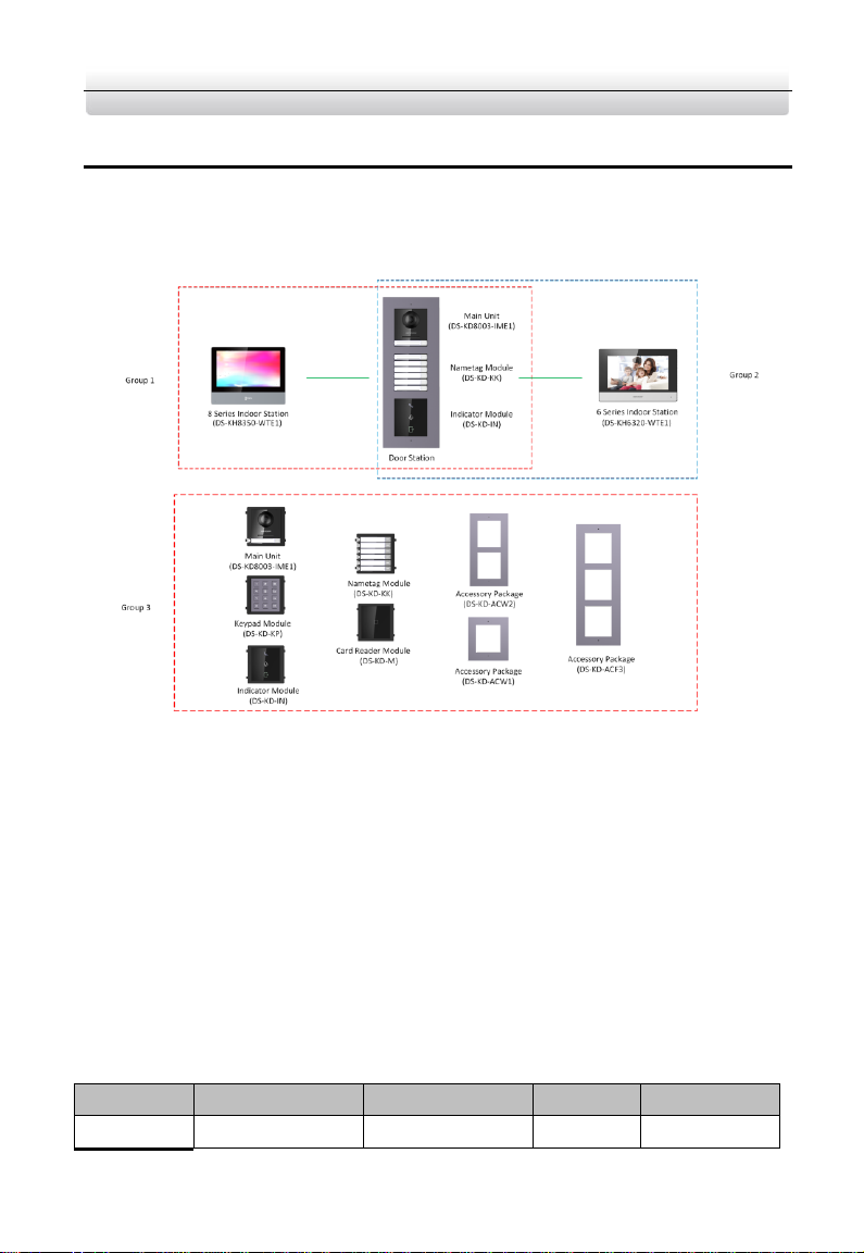
The demo case displays 3 groups of indoor station and door station.
See Figure 1-1 for the default calling relationship among these video intercom devices.
Figure 1-1 Intercom Application Diagram
1.2 Default Parameters
In the demo case, video intercom devices are divided into 3 groups by default.
The default configuration password for network indoor stations is 888999.
The default activation password of network video intercom devices in the demo
case is hik12345.
For DS-KH8350-WTE1 indoor station, the default Microphone volume, Prompt
Sound Volume and Call Volume are 70%.
For DS-KH6320-WTE1 indoor station, the default Microphone volume, Prompt
Sound Volume and Call Volume are 70%.
Refer to Table 1-1 to see the default parameters for each device.
Table 1-1 Device Information
Group No.
Device Type
Device Model
IP
Room No.
1
Indoor Station
DS-KH8350-WTE1
192.0.0.65
1
Video Intercom Demo Case·User Manual
2
Door Station
DS-KD8003-IME1/
Surface
192.0.0.64
Nametag Module
DS-KD-KK
Indicator Module
DS-KD-IN
2
Indoor Station
DS-KH6320-WTE1
192.0.0.66
2
Door Station
DS-KD8003-IME1/
Surface
192.0.0.64
Nametag Module
DS-KD-KK
Indicator Module
DS-KD-IN
2
Door Station
DS-KD8003-IME1/
Surface
192.0.0.65
Nametag Module
DS-KD-KK
Indicator Module
DS-KD-IN
Keypad Module
DS-KD-KP
Card Reader
Module
DS-KD-M

Video Intercom Demo Case·User Manual
3
2 Getting Started
2.1 Activate Indoor Station
You can only configure and operation the device after creating a password for the device
activation.
Steps:
1. Power on the device. It will enter the activation page automatically.
2. Create a password and confirm it.
3. Tap OK to activate the indoor station.
We highly recommend you to create a strong password of your own choosing
(using a minimum of 8 characters, including at least three kinds of following
categories: upper case letters, lower case letters, numbers, and special characters)
in order to increase the security of your product. And we recommend you reset
your password regularly, especially in the high security system, resetting the
password monthly or weekly can better protect your product.
2.2 Quick Operation
For DS-KH8350-WTE1 and DS-KH6320-WTE1, after device activation, the wizard page
will pop up.
Steps:
1. Choose language and tap Next.
Figure 2-1 Wizard-Language Settings
2. Set network parameters and tap Next.

Video Intercom Demo Case·User Manual
4
Figure 2-2 Wizard-Network Settings
1). Edit Local IP, Subnet Mask and Gateway parameters.
2). Enable DHCP, the device will get network parameters automatically.
3. Configure the indoor station and tap Next.
Figure 2-3 Wizard-Settings page
1). Choose Indoor station type.
2). Edit Floor and Room No.
4. Linked related devices and tap Next. If the device and the indoor station are in the
same LAN, the device will be displayed in the list. Tap the device or enter the serial
No. to link.

Video Intercom Demo Case·User Manual
5
Figure 2-4 Wizard-Related Devices Settings
1). Tap the door station in the list to link.
If the door station is inactive, the system will pop up the dialog to activate the
door station.
2). Tap to pop up the Network Settings page.
3). Edit the network parameters of the door station manually or enable DHCP to get
the network parameters automatically.
4). Tap OK to save the settings.
5. Tap Finish to save the settings.
2.3 Configure Sub Module Address
You need to set the sub module address via DIP before installation.
Steps:
1. Remove the rubber cover on the sub module rear panel to expose the DIP switch.
2. Set the sub module address according to the DIP rules, and install the rubber cover
back.
Digit 1, 2, 3, 4 are used to coding the sub module address; Digit 5, 6, 7 are reserved;
Digit 8 is a resistance (120Ω) is you set it as on.
Valid sub module address range is 1 to 8. The No. should be unique for sub modules
that connected to the same main unit.

Video Intercom Demo Case·User Manual
6
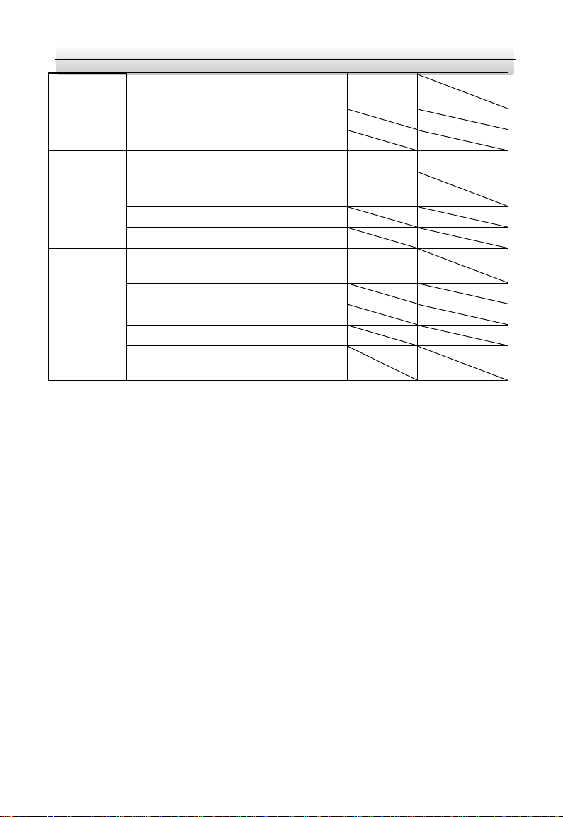
The sub module address and corresponding switch status as below.
Digit 1
Digit 2
Digit 3
Digit 4
1
ON
OFF
OFF
OFF 2 OFF
ON
OFF
OFF 3 ON
ON
OFF
OFF 4 OFF
OFF
ON
OFF 5 ON
OFF
ON
OFF 6 OFF
ON
ON
OFF 7 ON
ON
ON
OFF 8 OFF
OFF
OFF
ON
Sub
Module Address
DIP Switch Digit

Video Intercom Demo Case·User Manual
7
3 Video Intercom Function
3.1 Video Intercom Function of Group 1 and Group 2
For group 1, there are one 8-series indoor station and module door station.
For group 2, there are one 6-series indoor station and module door station.
Before you begin:
Make sure you have configured the room No. of the device.
Steps:
1. Press the call button on the main unit or on the nametag module to call the indoor
station.
2. The indoor station goes to the call receiving page automatically.

Video Intercom Demo Case·User Manual
8
Figure 3-1 Calling from Door Station
Tap to answer the call, and tap to reject the call.
Tap Unlock tab or the button to unlock the door.
Tap tab to capture the snapshots.
3.2 Video Intercom Function of Group 3
For group 3, there are 5 modules of door station and 3 accessory packages.
You can replace the modules in the group 1 of modules in group 2.
3.2.1 Call Resident
You can call corresponding resident in two ways:
1. Press the call button on the main unit or on the nametag module.
2. Enter the Room No. on the keypad module, and press # key to start calling.
(Press * to hang up.)

Video Intercom Demo Case·User Manual
9
Make sure you have configured the room No. of the device.
3.2.2 Issue Card
You cannot open door by swiping the card until you have issue the card.
Issue Card via Main Card: You can swipe card to issue it after swiping the main card in
advance.
Step:
1. Swipe the main card on the card reading area, and hear two beeps.
2. Swipe the unauthorized sub cards in turn after hearing a beep.
3. Swipe the main card again to end the card issuing process.
DS-KD-M supports Mifare card, DS-KD-E supports EM card.
If the amount of sub cards exceeds 2500, no more sub card can be issued.
3.2.3 Unlock Door
Unlock Door by Password
You can unlock the door by inputting the password via the keypad module.
Three formats of password are supported. They are:
1. 【#】+ Public Password +【#】
2. 【#】+ Room No. + Password +【#】
3. 【#】+ Room No. + Duress Password +【#】
Password contains 6 digits.
You’re allowed to set 3 public passwords via iVMS-4200.
The password varies according to different rooms.
Unlock Door by Card
Before you begin:
Make sure the card has been issued. You can issue the card via the door station, or via
iVMS-4200 client software.
Steps:
Swipe the card on the card induction area to unlock the door.
The main card does not support unlocking the door.

Video Intercom Demo Case·User Manual
10
3.3 Video Intercom Function Among Indoor Stations
When 2 indoor stations are connected to the same door station, these 2 indoor stations
can call each other.
Steps:
1. Set the No. of the door station.
Here we take the D series door station (DS-KD8003-IME1/Surface) as example, and
the default No. of the D series door station is 1-1-1.
2. Add the same door station to the 2 indoor stations.
1) Tap Settings -> -> Configuration, and input the configuration password to
enter the configuration page.
The default configuration password is 888999.
2) Tap to enter the device management page.
3) Tap Main Door Station tab, select the main door station type as Main Door
Station (D Series), and input the IP of the door station.
The default IP of the door station in the demo case is 192.0.0.70.
3. Set the Room No. for 2 indoor stations respectively.
1) Tap Local Info tab to enter the local information settings page of the indoor
station.
Figure 3-2 Local Information page
2) Set the Room No.
For Example:
You set the Room No. of DS-KH8350-WTE1 indoor station to 401, and set the
Room No. of DS-KH6320-WTE1 indoor station to 701.

Video Intercom Demo Case·User Manual
11
4. Start video intercom with the indoor station.
1) On the home page, tap Dial tab to enter the resident calling page.
Figure 3-3 Calling page
2) Enter the Room No., 1-1-1-401 or 401.
If 2 indoor stations are connected to the same door station, the community No.,
the building No., and the unit No. can be omitted when inputting the Room No. to
call the resident.
3) Tap tab to start an audiovisual call with the DS-KH8350-WTE1 indoor
station.

Video Intercom Demo Case·User Manual
12
4 Live View
For network indoor stations, you can get the live view of the added door stations on the
live view page of the indoor station.
Before you start:
Make sure both the door station and the indoor stations are well-connected.
Make sure the door station and the indoor stations have been activated.
Steps:
1. Add the same door station to the 2 indoor stations.
1) Tap Settings -> -> Configuration, and input the configuration password to
enter the configuration page.
The default configuration password is 888999.
2) Tap to enter the device management page.
3) Tap Main Door Station, select the main door station type as Main Door Station,
and input the IP of the door station.
The default IP of the door station in the demo case is 192.0.0.70.
2. On the home page, and tap Live View tab to enter the live view page.
Figure 4-1 Live View Page
3. Tap -> Main Door Station to get the live view of the door station.

Video Intercom Demo Case·User Manual
13
During the live view of door station, tap Unlock tab to open the door. Tap to call
the door station.

Video Intercom Demo Case·User Manual
14
5 Remote Operation via Mobile Client
You can configure and operate the device via Hik-Connect mobile client.
5.1 Set Up Mobile Client
Before you start:
Make sure your mobile device has been connected to network.
Steps:
1. Install Hik-Connect client and register a user account for iOS and Android.
1). Search Hik-Connect in App Store or Google Play
TM
to download and install the
client.
2). Launch the App and follow the on-screen instructions to register a user account.
2. Start the Hik-Connect client, and login the client.
5.2 Add Device
Before you start:
Make sure your device has been activated.
Make sure the door station and the indoor station are linked and communicating
normally.
Hik-Connect client is necessary for indoor station configuration and operation.
5.2.1 Add Device to APP via QR Code
You can add the door station and indoor station by scanning the QR code on the panel
of the device via the mobile client.
Figure 5-1 Scan the QR Code

Video Intercom Demo Case·User Manual
15
Tap Settings -> -> Hik-Connect Service to enable Hik-Connect Service before you
add the indoor station to the client.
Scan the QR code and edit the Verification Code on the page.
Figure 5-2 Hik-Connect Server Settings
5.2.2 Add Device to Mobile client via Serial No.
You can add the device to the mobile client by entering the device serial No.
You can get the serial No. on the Maintenance page: Settings ->Maintenance.
Figure 5-3 Enter the Serial No.

Video Intercom Demo Case·User Manual
16
UD14348B
 Loading...