


Swing Barrier
User Manual

Swing Barrier·User Manual
Product Name
Model
Swing Barrier
User Manual
© 2018 Hangzhou Hikvision Digital Technology Co., Ltd.
This manual applies to swing barrier.
DS-K3B801-M/M
About this Manual
This Manual is subject to domestic and international copyright protection. Hangzhou
Hikvision Digital Technology Co., Ltd. (“Hikvision”) reserves all rights to this manual. This manual
cannot be reproduced, changed, translated, or distributed, partially or wholly, by any means,
without the prior written permission of Hikvision.
Trademarks
and other Hikvision marks are the property of Hikvision and are
registered trademarks or the subject of applications for the same by Hikvision and/or its
affiliates. Other trademarks mentioned in this manual are the properties of their respective
owners. No right of license is given to use such trademarks without express permission.
Disclaimer
TO THE MAXIMUM EXTENT PERMITTED BY APPLICABLE LAW, HIKVISION MAKES NO
WARRANTIES, EXPRESS OR IMPLIED, INCLUDING WITHOUT LIMITATION THE IMPLIED
WARRANTIES OF MERCHANTABILITY AND FITNESS FOR A PARTICULAR PURPOSE,
REGARDING THIS MANUAL. HIKVISION DOES NOT WARRANT, GUARANTEE, OR MAKE ANY
REPRESENTATIONS REGARDING THE USE OF THE MANUAL, OR THE CORRECTNESS, ACCURACY,
OR RELIABILITY OF INFORMATION CONTAINED HEREIN. YOUR USE OF THIS MANUAL AND ANY
RELIANCE ON THIS MANUAL SHALL BE WHOLLY AT YOUR OWN RISK AND RESPONSIBILITY.
REGARDING TO THE PRODUCT WITH INTERNET ACCESS, THE USE OF PRODUCT SHALL BE
WHOLLY AT YOUR OWN RISKS. OUR COMPANY SHALL NOT TAKE ANY RESPONSIBILITIES FOR
ABNORMAL OPERATION, PRIVACY LEAKAGE OR OTHER DAMAGES RESULTING FROM CYBER
ATTACK, HACKER ATTACK, VIRUS INSPECTION, OR OTHER INTERNET SECURITY RISKS;
HOWEVER, OUR COMPANY WILL PROVIDE TIMELY TECHNICAL SUPPORT IF REQUIRED.
SURVEILLANCE LAWS VARY BY JURISDICTION. PLEASE CHECK ALL RELEVANT LAWS IN
YOUR JURISDICTION BEFORE USING THIS PRODUCT IN ORDER TO ENSURE THAT YOUR USE
CONFORMS THE APPLICABLE LAW. OUR COMPANY SHALL NOT BE LIABLE IN THE EVENT THAT THIS
PRODUCT IS USED WITH ILLEGITIMATE PURPOSES.
IN THE EVENT OF ANY CONFLICTS BETWEEN THIS MANUAL AND THE APPLICABLE LAW, THE LATER
PREVAILS.
Support
Should you have any questions, please do not hesitate to contact your local dealer.
i

Swing Barrier·User Manual
Regulatory Information
FCC Information
Please take attention that changes or modification not expressly approved by the party responsible
for compliance could void the user’s authority to operate the equipment.
FCC compliance: This equipment has been tested and found to comply with the limits for a Class B
digital device, pursuant to part 15 of the FCC Rules. These limits are designed to provide
reasonable protection against harmful interference in a residential installation. This equipment
generates, uses and can radiate radio frequency energy and, if not installed and used in accordance
with the instructions, may cause harmful interference to radio communications. However, there is
no guarantee that interference will not occur in a particular installation. If this equipment does
cause harmful interference to radio or television reception, which can be determined by turning
the equipment off and on, the user is encouraged to try to correct the interference by one or more
of the following measures:
—Reorient or relocate the receiving antenna.
—Increase the separation between the equipment and receiver.
—Connect the equipment into an outlet on a circuit different from that to which the receiver is
connected.
—Consult the dealer or an experienced radio/TV technician for help.
FCC Conditions
This device complies with part 15 of the FCC Rules. Operation is subject to the following
two conditions:
1. This device may not cause harmful interference.
2. This device must accept any interference received, including interference that may cause
undesired operation.
EU Conformity Statement
This product and - if applicable - the supplied accessories too are marked with "CE"
and comply therefore with the applicable harmonized European standards listed
under the RE Directive 2014/53/EU, the EMC Directive 2014/30/EU, the RoHS
Directive 2011/65/EU.
2012/19/EU (WEEE directive): Products marked with this symbol cannot be disposed
of as unsorted municipal waste in the European Union. For proper recycling, return
this product to your local supplier upon the purchase of equivalent new equipment,
or dispose of it at designated collection points. For more information see:
www.recyclethis.info
ii

Swing Barrier·User Manual
2006/66/EC (battery directive): This product contains a battery that cannot be
disposed of as unsorted municipal waste in the European Union. See the product
documentation for specific battery information. The battery is marked with this
symbol, which may include lettering to indicate cadmium (Cd), lead (Pb), or
mercury (Hg). For proper recycling, return the battery to your supplier or to a
designated collection point. For more information see: www.recyclethis.info
Industry Canada ICES-003 Compliance
This device meets the CAN ICES-3 (B)/NMB-3(B) standards requirements.
This device complies with Industry Canada licence-exempt RSS standard(s). Operation is subject to
the following two conditions:
(1) this device may not cause interference, and
(2) this device must accept any interference, including interference that may cause undesired
operation of the device.
Le présent appareil est conforme aux CNR d'Industrie Canada applicables aux appareils
radioexempts de licence. L'exploitation est autorisée aux deux conditions suivantes :
(1) l'appareil ne doit pas produire de brouillage, et
(2) l'utilisateur de l'appareil doit accepter tout brouillage radioélectrique subi, même si le
brouillage est susceptible d'en compromettre le fonctionnement.
Under Industry Canada regulations, this radio transmitter may only operate using an antenna of a
type and maximum (or lesser) gain approved for the transmitter by Industry Canada. To reduce
potential radio interference to other users, the antenna type and its gain should be so chosen that
the equivalent isotropically radiated power (e.i.r.p.) is not more than that necessary for successful
communication.
Conformément à la réglementation d'Industrie Canada, le présent émetteur radio peut
fonctionner avec une antenne d'un type et d'un gain maximal (ou inférieur) approuvé pour
l'émetteur par Industrie Canada. Dans le but de réduire les risques de brouillage radioélectrique à
l'intention des autres utilisateurs, il faut choisir le type d'antenne et son gain de sorte que la
puissance isotrope rayonnée équivalente (p.i.r.e.) ne dépasse pas l'intensité nécessaire à
l'établissement d'une communication satisfaisante.
Safety Instruction
These instructions are intended to ensure that user can use the product correctly to avoid
danger or property loss.
The precaution measure is divided into Warnings and Cautions:
Warnings: Neglecting any of the warnings may cause serious injury or death.
Cautions: Neglecting any of the cautions may cause injury or equipment damage.
iii
Swing Barrier·User Manual
Warnings Follow
these safeguards to
prevent serious
injury or death.
Cautions Follow these
precautions to prevent
potential injury or
material damage.
Warnings
All the electronic operation should be strictly compliance with the electrical safety regulations,
fire prevention regulations and other related regulations in your local region.
Please make sure the device is connected to ground.
Please use the power supply, which is provided by normal company. The power consumption
cannot be less than the required value.
Do not connect several devices to one power supply as the overload may cause over-heat or fire
hazard.
Please make sure that the power has been disconnected before you wire, install or dismantle
the device.
If the top caps should be open and the device should be powered on for maintenance, make
sure:
1. Power off the fan to prevent the operator from getting injured accidently.
2. Do not touch bare high-voltage components.
3. Make sure the switch’s wiring sequence is correct after maintenance.
When the product is installed on wall or ceiling, the device shall be firmly fixed.
If smoke, odors or noise rise from the device, turn off the power at once and unplug the power
cable, and then please contact the service center.
If the product does not work properly, please contact your dealer or the nearest service center.
Never attempt to disassemble the device yourself. (We shall not assume any responsibility for
problems caused by unauthorized repair or maintenance.)
Exit the lane when the lane controller is rebooting.
Cautions
Stainless steel may be corroded in some circumstances. You need to clean and care the device
by using the stainless steel cleaner. It is suggested to clean the device every month.
Do not drop the device or subject it to physical shock, and do not expose it to high
electromagnetism radiation. Avoid the equipment installation on vibrations surface or places
subject to shock (ignorance can cause equipment damage).
Do not place the device in extremely hot (refer to the specification of the device for the detailed
operating temperature), cold, dusty or damp locations, and do not expose it to high
electromagnetic radiation.
The device cover for indoor use shall be kept from rain and moisture.
iv

Swing Barrier·User Manual
Exposing the equipment to direct sun light, low ventilation or heat source such as heater or
radiator is forbidden (ignorance can cause fire danger).
Do not aim the device at the sun or extra bright places. A blooming or smear may occur
otherwise (which is not a malfunction however), and affecting the endurance of sensor at the
same time.
Please use the provided glove when open up the device cover, avoid direct contact with the
device cover, because the acidic sweat of the fingers may erode the surface coating of the device
cover.
Please use a soft and dry cloth when clean inside and outside surfaces of the device cover, do
not use alkaline detergents.
Please keep all wrappers after unpack them for future use. In case of any failure occurred, you
need to return the device to the factory with the original wrapper. Transportation without the
original wrapper may result in damage on the device and lead to additional costs.
Improper use or replacement of the battery may result in hazard of explosion. Replace with the
same or equivalent type only. Dispose of used batteries according to the instructions provided by
the battery manufacturer.
Do not stay in the lane when the device is rebooting.
RISK OF EXPLOSION IF BATTERY IS REPLACED BY AN INCORRECT TYPE. DISPOSE OF USED
BATTERIES ACCORDING TO THE INSTRUCTIONS.
SUITABLE FOR MOUNTING ON CONCRETE OR OTHER NON-COMBUSTIBLE SURFACE ONLY.
v

Swing Barrier·User Manual
Table of Contents
Chapter 1 Overview ................................................................................................................. 1
1.1 Introduction ......................................................................................................................... 1
1.2 Main Features ...................................................................................................................... 1
Chapter 2 Installation .............................................................................................................. 3
2.1 Disassembling before Installation ........................................................................................ 3
2.2 Installing Device ................................................................................................................... 7
Chapter 3 Disassembling before Maintenance .......................................................................... 9
Chapter 4 Wiring ................................................................................................................... 15
4.1 Components Introduction .................................................................................................. 15
4.2 Wiring Electric Supply ........................................................................................................ 16
4.3 Wiring Interconnecting Cable ............................................................................................ 17
4.3.1 General Wiring ............................................................................................................... 19
4.3.2 Wiring Face Recognition Terminal (Optional) ................................................................ 20
4.4 Terminal Description .......................................................................................................... 21
4.4.3 Master Control Board Terminal Description .................................................................. 21
4.4.4 Slave Control Board Terminal Description ..................................................................... 21
4.4.5 Main Control Board Terminal Description ..................................................................... 22
4.4.6 Main Control Board Serial Port ID Description .............................................................. 25
4.4.7 RS-485 Wiring ................................................................................................................ 27
4.4.8 RS-232 Wiring ................................................................................................................ 27
4.4.9 Wiegand Wiring ............................................................................................................. 28
4.4.10 Barrier Control Wiring ................................................................................................ 29
4.4.11 Alarm Output Wiring.................................................................................................. 30
4.5 Wiring Lithium Battery (Optional) ..................................................................................... 30
Chapter 5 Device Settings ...................................................................................................... 33
5.1 Setting Closed Position ....................................................................................................... 33
5.2 Pairing Keyfob (Optional) ................................................................................................... 34
5.3 Initializing Device ............................................................................................................... 34
5.4 Switching RS-485/RS-232 Mode ......................................................................................... 35
5.5 Switching Relay Output Mode (NO/NC) ............................................................................. 35
5.5.1 Barrier Control Relay Output Mode ............................................................................... 35
5.5.2 Alarm Relay Output Mode (NO/NC)............................................................................... 36
Chapter 6 Device Activation ................................................................................................... 37
6.1 Activating via SADP Software ............................................................................................. 37
vi

Swing Barrier·User Manual
vii
6.2 Activating via Client Software ............................................................................................ 38
Chapter 7 Client Operation .................................................................................................... 41
7.1 Function Module ................................................................................................................ 41
7.2 Access Control Management ............................................................................................. 41
7.2.1 Adding Access Control Device ........................................................................................ 42
7.2.2 Viewing Device Status .................................................................................................... 53
7.2.3 Editing Basic Information ............................................................................................... 54
7.2.4 RS-485 Settings ............................................................................................................... 54
7.2.5 Authenticating M1 Card Encryption............................................................................... 55
7.2.6 Remote Configuration .................................................................................................... 56
7.3 Organization Management ................................................................................................ 65
7.3.1 Adding Organization ....................................................................................................... 66
7.3.2 Modifying and Deleting Organization ............................................................................ 66
7.4 Person Management .......................................................................................................... 66
7.4.1 Adding Person ................................................................................................................ 66
7.4.2 Managing Person............................................................................................................ 77
7.4.3 Issuing Card in Batch ...................................................................................................... 78
7.5 Permission Configuration ................................................................................................... 79
7.5.1 Adding Permission .......................................................................................................... 80
7.5.2 Applying Permission ....................................................................................................... 81
7.6 Advanced Functions ........................................................................................................... 82
7.6.1 Access Control Parameters ............................................................................................. 82
7.6.2 Card Reader Authentication ........................................................................................... 85
7.6.3 Multiple Authentication ................................................................................................. 87
7.6.4 Open Door with First Card ............................................................................................. 90
7.6.5 Anti-Passing Back ........................................................................................................... 91
7.6.6 Cross-Controller Anti-passing Back ................................................................................ 92
7.7 Searching Access Control Event ......................................................................................... 95
7.7.1 Searching Local Access Control Event ............................................................................ 96
7.7.2 Searching Remote Access Control Event ........................................................................ 96
7.8 Access Control Event Configuration ................................................................................... 97
7.8.1 Access Control Event Linkage ......................................................................................... 97
7.8.2 Access Control Alarm Input Linkage ............................................................................... 98
7.8.3 Event Card Linkage ......................................................................................................... 99
7.8.4 Cross-Device Linkage .................................................................................................... 102
7.9 Door Status Management ................................................................................................ 103

Swing Barrier·User Manual
7.9.1 Access Control Group Management ............................................................................ 103
7.9.2 Anti-control the Access Control Point (Door) ............................................................... 105
7.9.3 Status Duration Configuration ..................................................................................... 106
7.9.4 Real-time Card Swiping Record .................................................................................... 108
7.9.5 Real-time Access Control Alarm ................................................................................... 108
7.10 Arming Control ................................................................................................................. 109
7.11 Time and Attendance ....................................................................................................... 110
7.11.1 Shift Schedule Management .................................................................................... 111
7.11.2 Attendance Handling ................................................................................................ 117
Appendix A Tips for Scanning Fingerprint ............................................................................ 120
Appendix B DIP Switch Description ..................................................................................... 121
DIP Switch Introduction ............................................................................................................... 121
DIP Switch Corresponded Functions ............................................................................................ 121
Appendix C Table of Audio Index Related Content ............................................................... 122
viii
Swing Barrier·User Manual
1
Chapter 1 Overview
1.1 Introduction
The swing barrier with two barriers and 12 IR lights is designed to detect unauthorized entrance or exit. By
adopting the swing barrier integrated with the access control system, person should authenticate to pass
through the lane via swiping IC or ID card, scanning QR code, etc. It is widely used in attractions, stadiums,
construction sites, residences, etc.
1.2 Main Features
32-bit high-speed processor
TCP/IP network communication
The communication data is specially encrypted to relieve the concern of privacy leak
Permissions validation and anti-tailgating
Remaining open/closed mode selectable
Bidirectional (Entering/Exiting) lane
The barrier opening and closing speed can be configured according to the visitors flow
The barrier will be locked or stop working when people are nipped.
Anti-forced-accessing
The barrier will be locked automatically without open-barrier signal. It can bear the force of up
to 120 Nm.
Self-detection, Self-diagnostics, and automatic alarm
Audible and visual alarm will be triggered when detecting intrusion, tailgating, reverse passing,
climbing over barrier, and overstay.
IP conflict detection
Remote control and management
Online/offline operation
LED indicates the entrance/exit and light bar indicates passing status.

Swing Barrier·User Manual
2
Barrier is in free status when powered down; If the device is installed with lithium battery
(optional), the barrier remains open when powered down
Fire alarm passing
When the fire alarm is triggered, the barrier will be open automatically for emergency
evacuation.
Valid passing duration settings
System will cancel the passing permission if a person does not pass through the lane within the
valid passing duration
Opens/closes barrier according to the schedule template
Adds up to 3000 visitor cards and up to 60,000 cards except for visitor cards
Stores up to 180000 card swiping records
Supports anti-passback of single lane and cross-controller anti-passback
Swing Barrier·User Manual
3
Chapter 2 Installation
2.1 Disassembling before Installation
Purpose:
Before installation, you should disassemble the pedestal and remove some screws.
Notes:
Keep the disassembled components and screws organized.
You should prepare the following tools to disassemble the pedestal: 1. Pedestal Key (supplied);
2. Allen Wrench (2.5 mm); 3. Allen Wrench (3 mm); 4. Allen Wrench (4 mm).
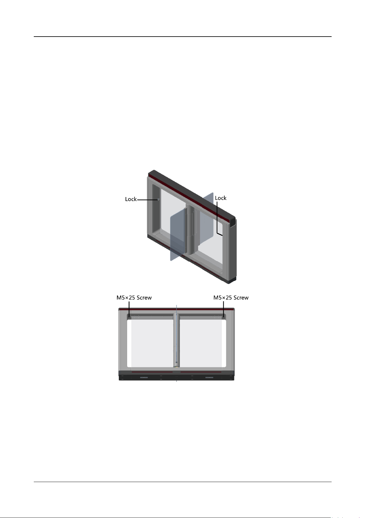
Steps:
1. Use the pedestal key to open the front and back components
2. Use the Allen wretch (4 mm) to loosen the 2 screws (M5 × 25) at the top of the device.
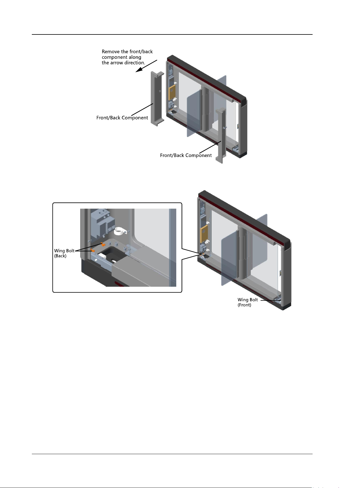
3. Remove the components along the arrow direction carefully.
Swing Barrier·User Manual
4
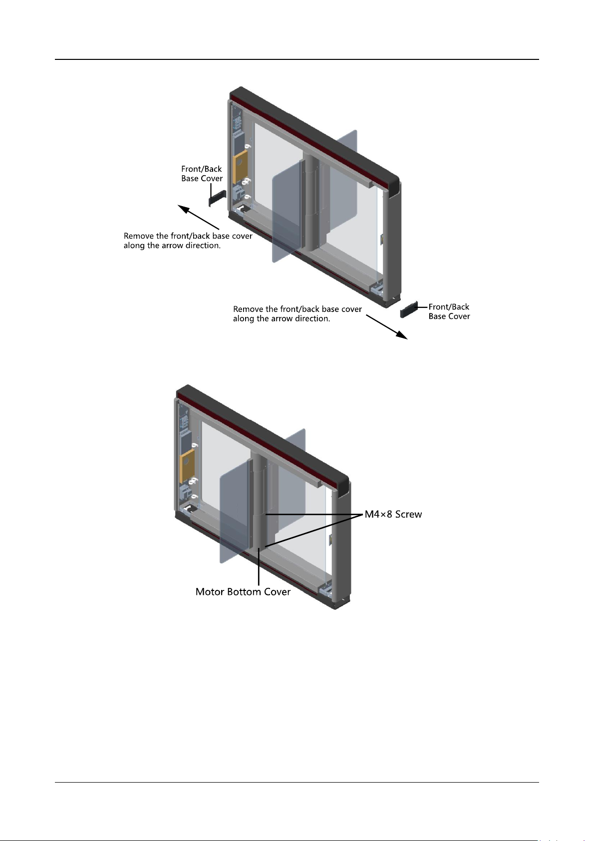
4. Loosen the wing bolt (M4 × 10) at the front and back of the pedestal, and remove the front and
back base covers along the arrow direction.
You can start installing the expansion screws to secure the device on the installation surface.
Swing Barrier·User Manual
5
5. Remove the motor bottom cover.
1) Pull or push the barrier to the closed position.
2) Use the Allen wretch (2.5 mm) to loosen the 4 screws (M4 × 8) on the motor bottom cover.
3) Pull or push the barrier to the open position, and remove the motor bottom cover.
Swing Barrier·User Manual
6
Note: If dissembling the middle pedestal, you should dissemble two motor bottom covers.
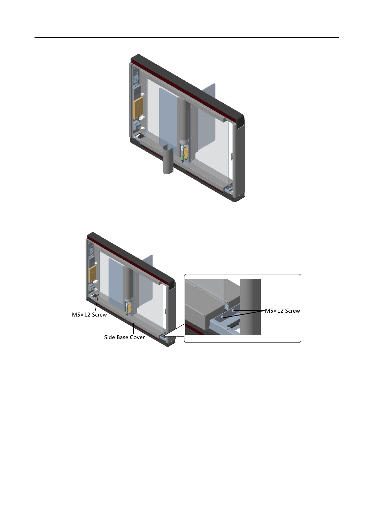
6. Use the Allen wretch (4 mm) to loosen the 2 screws (M5 × 12) at the front or back of the
pedestal base and remove the side base cover slowly.
Note: If dissembling the middle pedestal, you should dissemble two side base covers.
7. Disassemble the two protective sheets at the bottom for wiring, and you can start wiring the
interconnecting cable.

Swing Barrier·User Manual
7
2.2 Installing Device
Before you start:
Prepare for the installation tools, check the device and the accessories, and clear the installation
base.
Notes:
SUITABLE FOR MOUNTING ON CONCRETE OR OTHER NON-COMBUSTIBLE SURFACE ONLY.
In general, because of the limitation of installation and maintenance, the suggested distance
between the wall and the pedestal is more than 50 mm.
Steps:
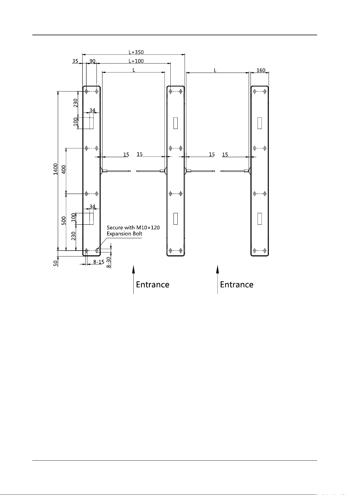
1. Draw a line on central installation surface of the left or right pedestal.
2. Draw another two parallel lines for installing the other two pedestals.
Note: The distance between the nearest two line is L+100 mm. L represents the lane width.
3. Drill holes on the ground according to the installation holes on the pedestals and insert the
expansion sleeves.
4. Bury interconnecting cables for pedestal communication.
Note: For detailed information about burying and wiring interconnecting cables, see 4.3 Wiring
Interconnecting Cable.
5. According to the entrance and exit marks on the pedestals, move the pedestals to the
corresponded positions.
Note: Make sure the installation holes on the pedestals and the base are aligned with each
other.
6. Secure the pedestals with expansion bolts.
The installation footprint is as follows:
Swing Barrier·User Manual
8
Unit: mm
7. After installation, assemble the components and screws back to the pedestal in reverse order
(except for protective sheets).
Swing Barrier·User Manual
9
Chapter 3 Disassembling before
Maintenance
Purpose:
Before maintaining the inner components, you should disassemble the pedestal and remove some
screws.
Notes:
Keep the disassembled components and screws organized.
You should prepare the following tools to disassemble the pedestal: 1. Pedestal Key (supplied);
2. Allen Wrench (2.5 mm); 3. Allen Wrench (3 mm); 4. Allen Wrench (4 mm).
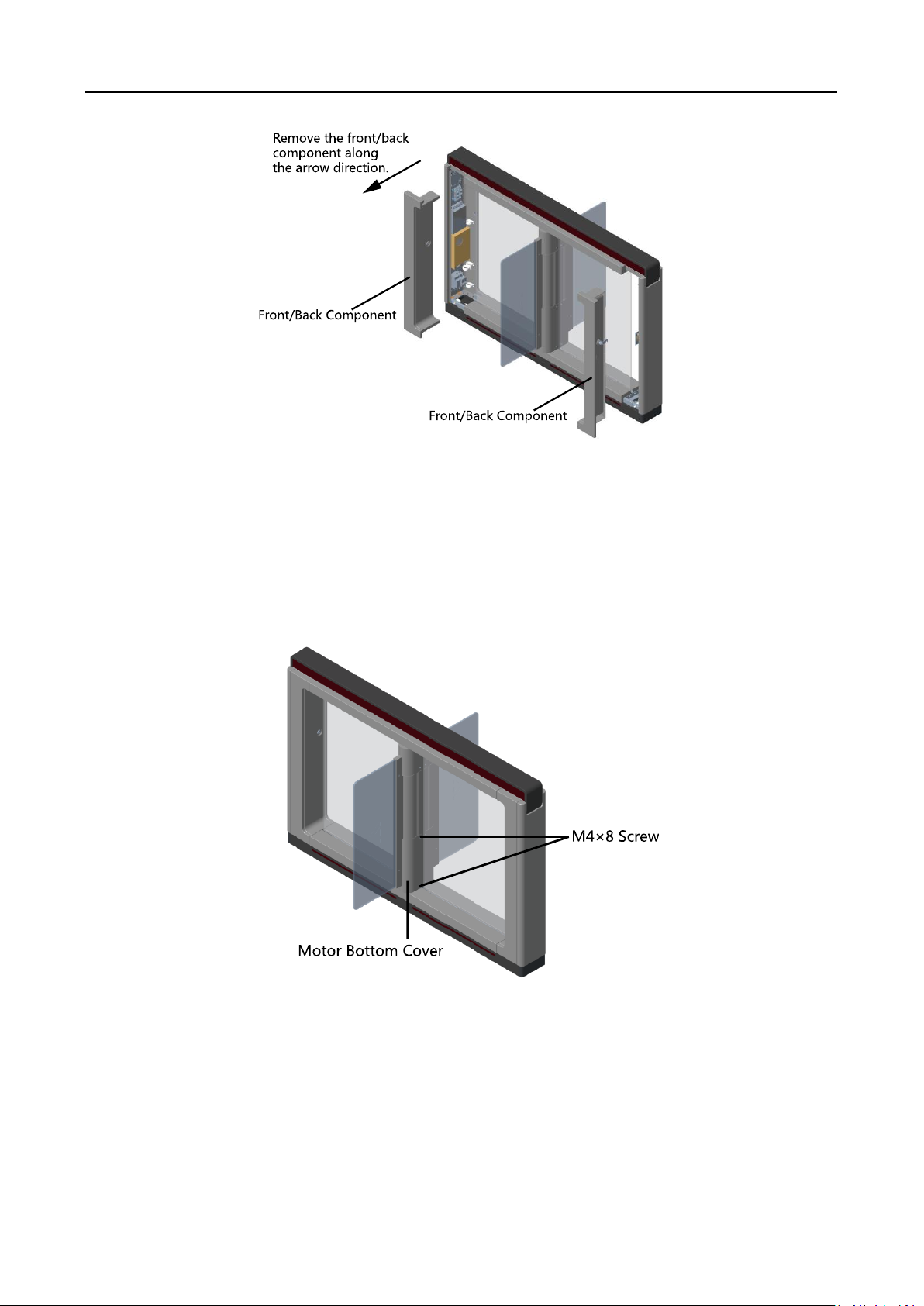
Disassembling Front and Back Components
Purpose:
After disassembling the front and back components, you can maintain the front and back parts of
the pedestal.
Steps:
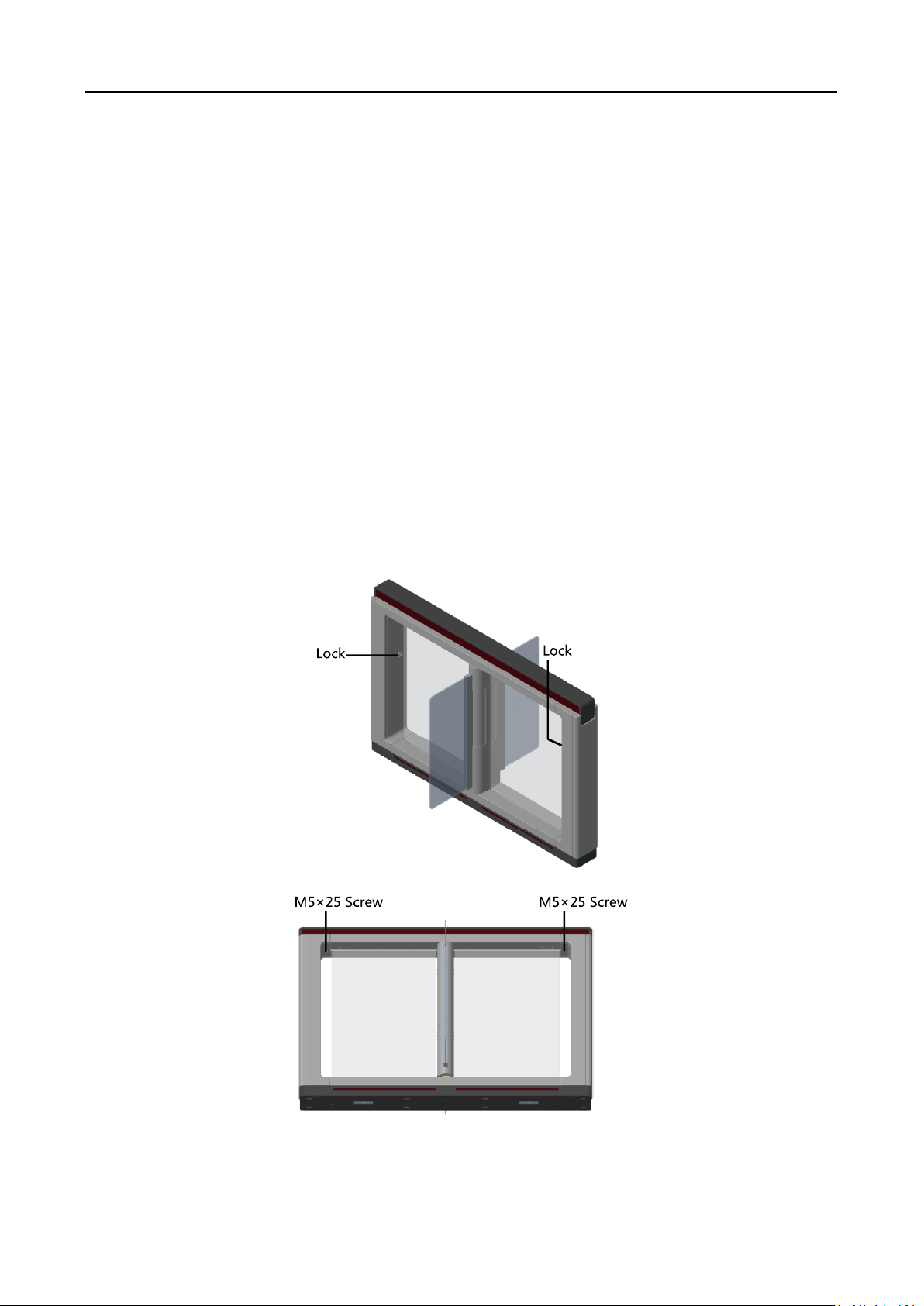
1. Use the pedestal key to open the front and back components.
2. Use the Allen wretch (4 mm) to loosen the 2 screws (M5 × 25) at the top of the device.
3. Remove the components along the arrow direction carefully.
Swing Barrier·User Manual
10
Disassembling Motor Bottom Cover
Purpose:
After disassembling the motor bottom cover, you can maintain the lane control board and the
barrier position control board.
Steps:
1. Pull or push the barrier to the closed position.
2. Use the Allen wretch (2.5 mm) to loosen the 4 screws (M4 × 8) on the motor bottom cover.
3. Pull or push the barrier to the open position, and remove the motor bottom cover.
Swing Barrier·User Manual
11
Note: If dissembling the middle pedestal, you should dissemble two motor bottom covers.
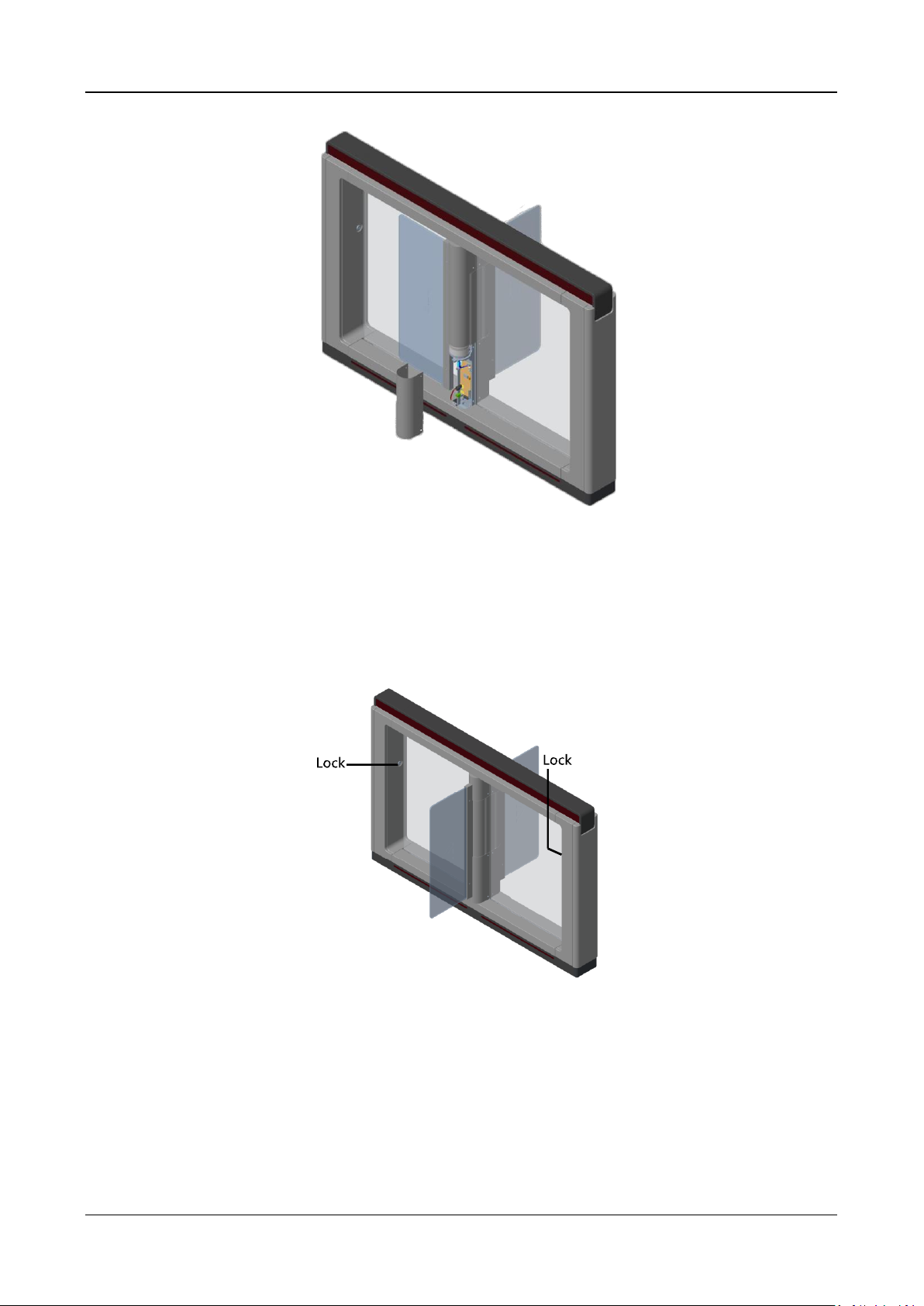
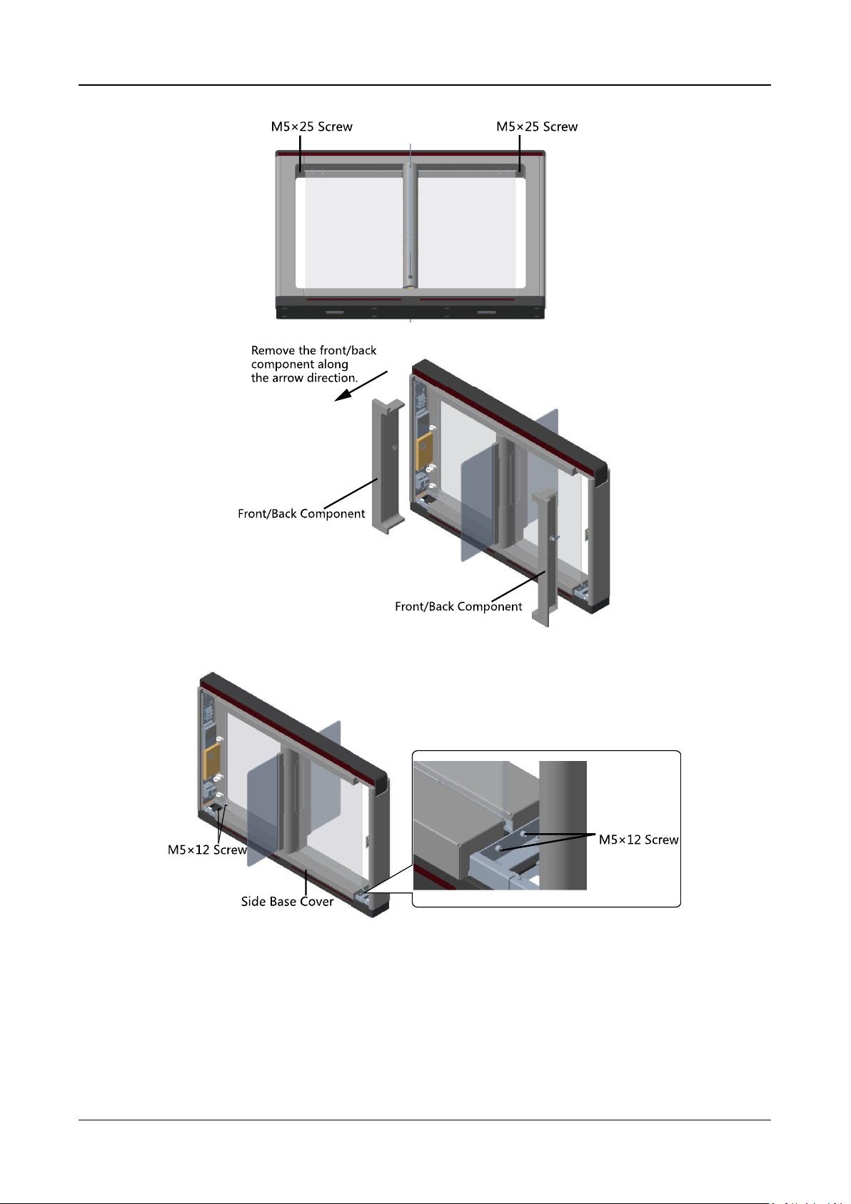
Disassembling Side Base Cover
Purpose:
After disassembling the side base cover, you can maintain the IR sending/receiving board.
Steps:
1. Use the pedestal key to open the front and back components.
2. Use the Allen wretch (4 mm) to loosen the 2 screws (M5 × 25) at the top of the device.
Swing Barrier·User Manual
12
3. Remove the components along the arrow direction carefully.
4. Use the Allen wretch (4 mm) to loosen the 2 screws (M5 × 12) at the front or back of the
pedestal base and remove the side base cover slowly.
Note: If dissembling the middle pedestal, you should dissemble two side base covers.
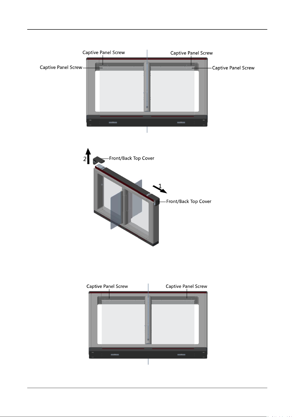
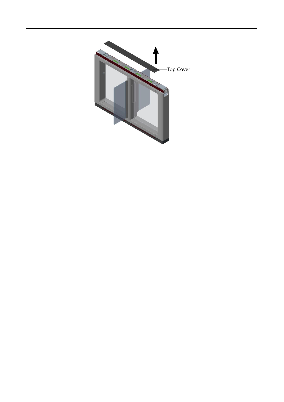
Disassembling Top Cover
Purpose:
After disassembling the top cover, you can maintain the components at the top of the pedestal, the
IR sending/receiving board and the IR adaptor for instance.
Steps:
Swing Barrier·User Manual
13
1. Use the Allen wretch (2.5 mm) to loosen the 4 captive panel screws at the top of the pedestal.
2. Move the front and back top covers along the arrow 1’s direction for about 3 cm, and move
them upwards to remove the front and back top covers.
3. (Optional) If you should install the fingerprint modules in the pedestal, you should use the key
to open and remove the front and back components, and cut off the fingerprint modules’
power.
4. Use the Allen wrench (2.5 mm) to loosen the 2 captive panel screws displayed in the picture
below.
5. Remove the top cover along the arrow’s direction.
Swing Barrier·User Manual
14
Swing Barrier·User Manual
15
Chapter 4 Wiring
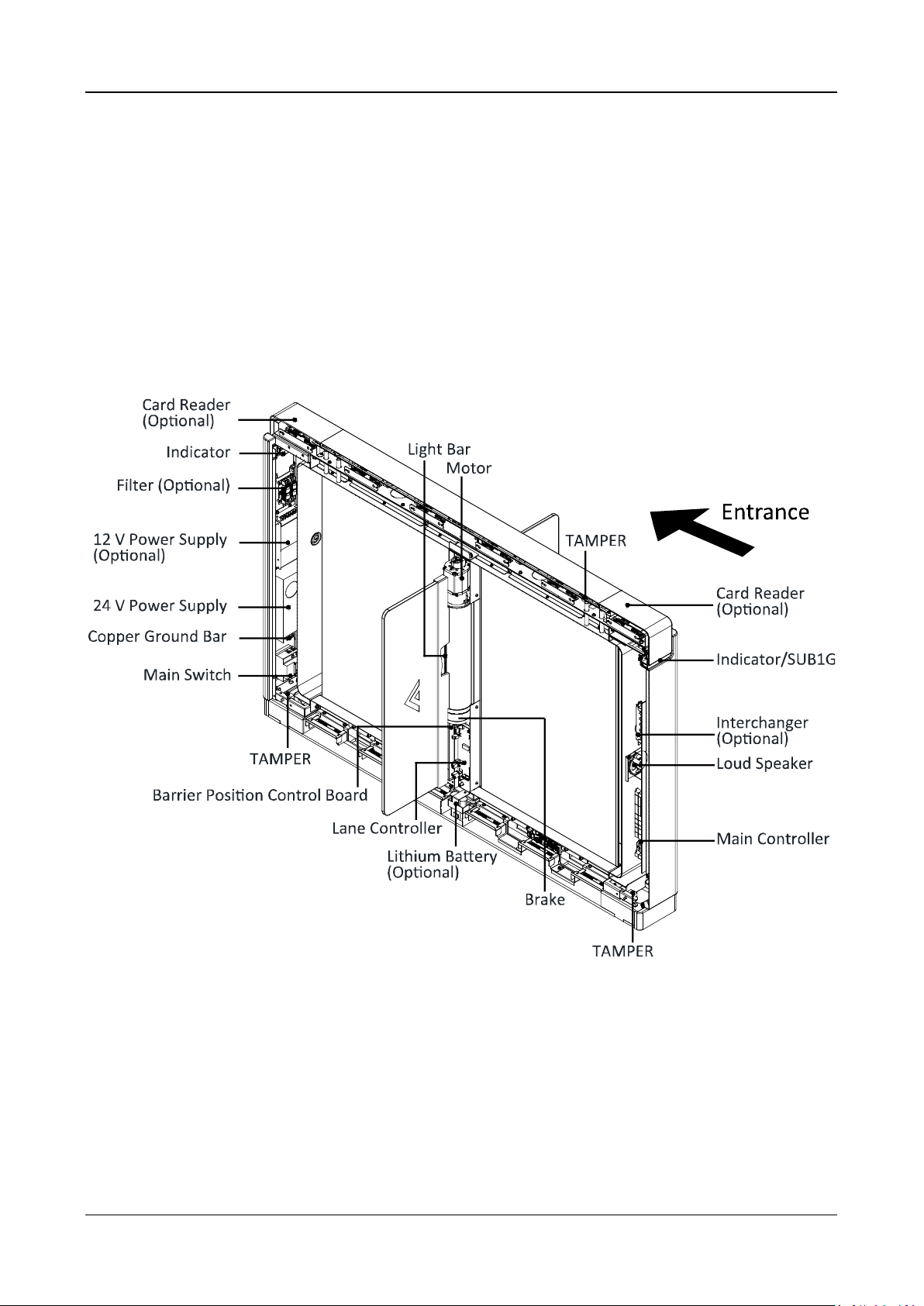
4.1 Components Introduction
Purpose:
By default, basic components of the swing barrier are connected well. The pedestals can realize
communications between pedestals by the wirings of the interconnecting cables. And the swing
barrier should wire to the AC electric supply for the whole system’s power supply.
Note: The voltage fluctuation of the electric supply is between 100 VAC and 220 VAC, 50 to 60 Hz.
The picture displayed below describes each component’s position on the swing barrier.
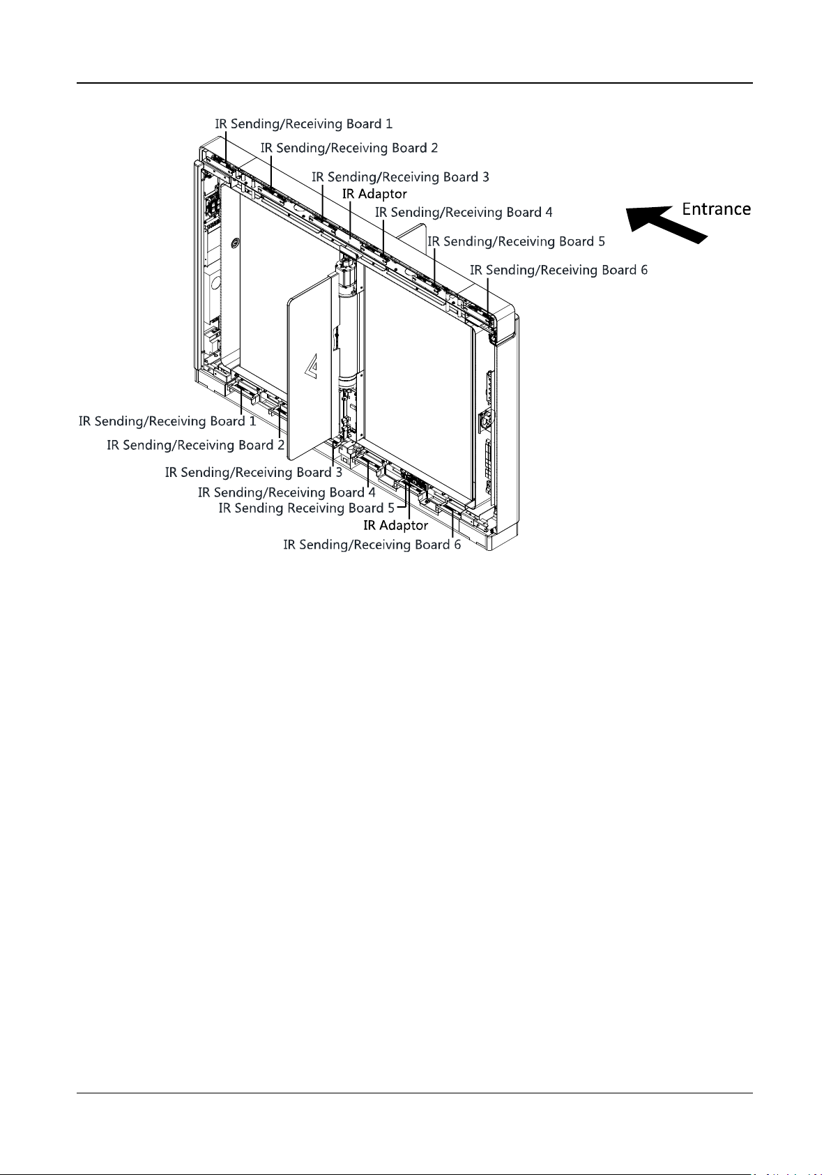
The positions of IR adaptor and IR sending/receiving board are as follows:
Swing Barrier·User Manual
16
Note: When you stand at the entrance, the IR sending boards are in the left pedestal and the right
side of the middle pedestal, the IR receiving boards are in the right pedestal and the left side of the
middle pedestal.
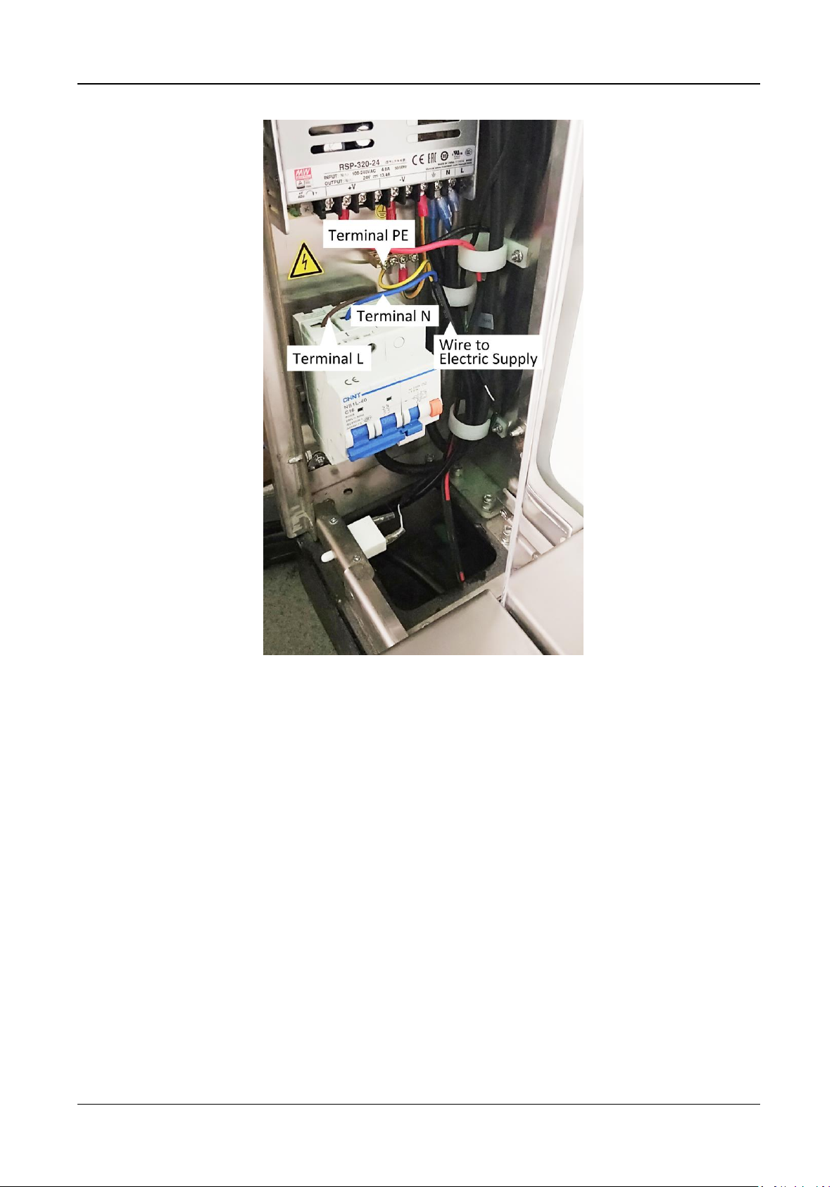
4.2 Wiring Electric Supply
Wire electric supply with the switch in the pedestal. Terminal L and terminal N are on the main
switch, while terminal PE should connect to a ground wire (yellow and green wire).
Swing Barrier·User Manual
17
Notes:
The cable bare part should be no more than 8 mm. It is suggested that you can immerse the
bare part into the liquid tin. If possible, ware an insulation cap at the end of the bare cable.
Make sure there’s no bare copper or cable after the wiring.
The Terminal L and the Terminal N cannot be wired reversely.
Do not wire the input and output terminal reversely.
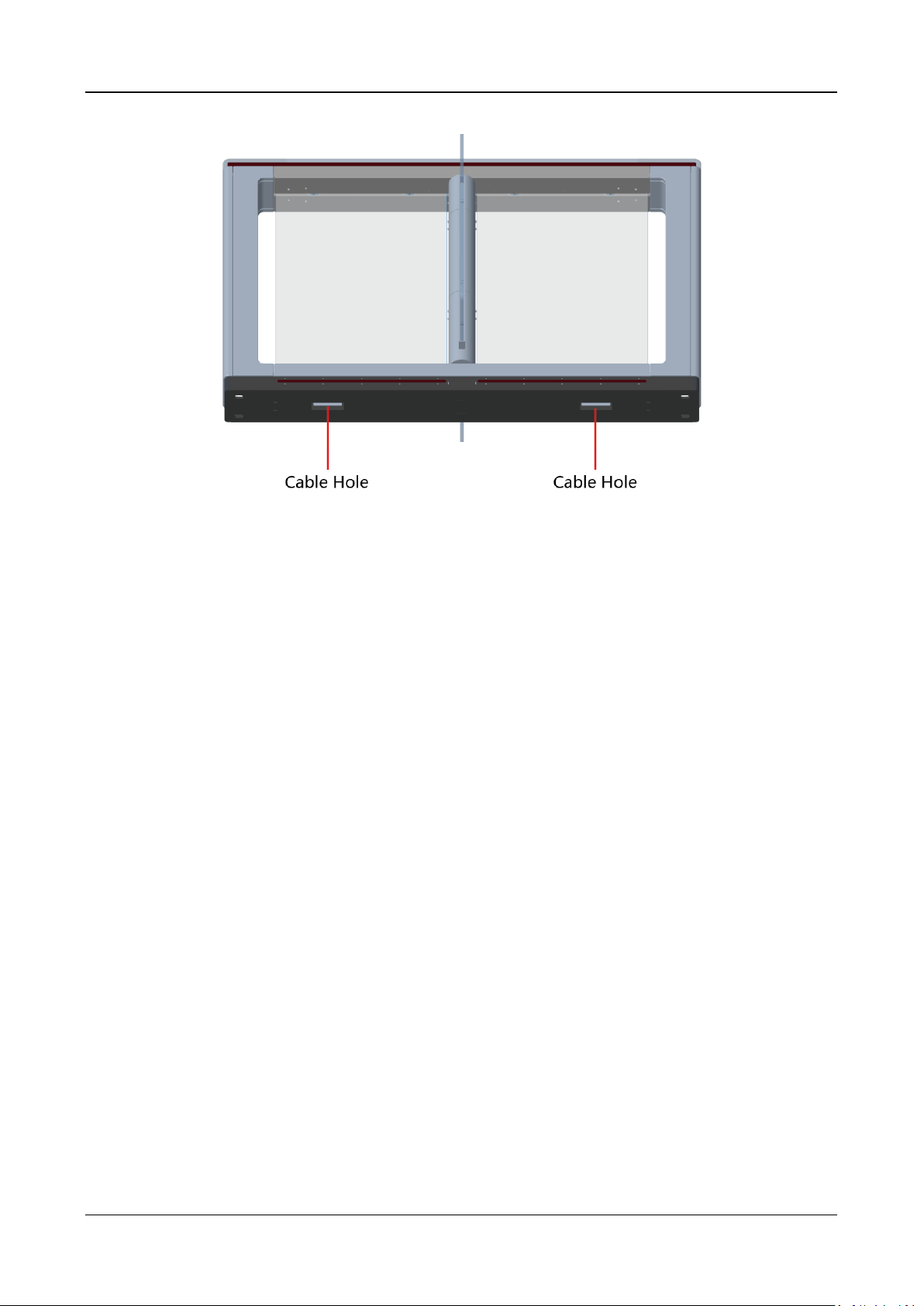
4.3 Wiring Interconnecting Cable
Purpose:
You should use interconnecting cables to connect the master lane board and the slave lane board
for components communication.
The picture displayed below describes the cable hole’s position on the pedestals.
Swing Barrier·User Manual
18
Swing Barrier·User Manual
19
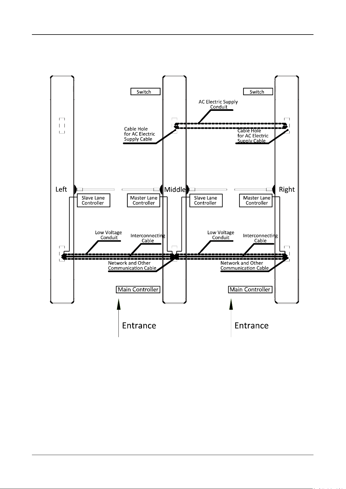
4.3.1 General Wiring
Notes:
The supplied interconnecting cable length is 3.75 m. If you need a longer one, ask our
technique supports or sales and purchase 5.5 m interconnecting cables.
If you want to bury both of the AC power cord and the low voltage cable at the same side, the
two cables should be in separated conduits to avoid interference.
If more peripherals are required to connect, you should increase the conduit diameter or bury
another conduit for the external cable.
The external AC power cord should be double-insulated.
The suggested network cable should be CAT5e or the network cable has better performance.
And the suggested network cable length should be less than 100 m. If the communication
length is more than 100 m, it is suggested to use optical fiber.
Swing Barrier·User Manual
20
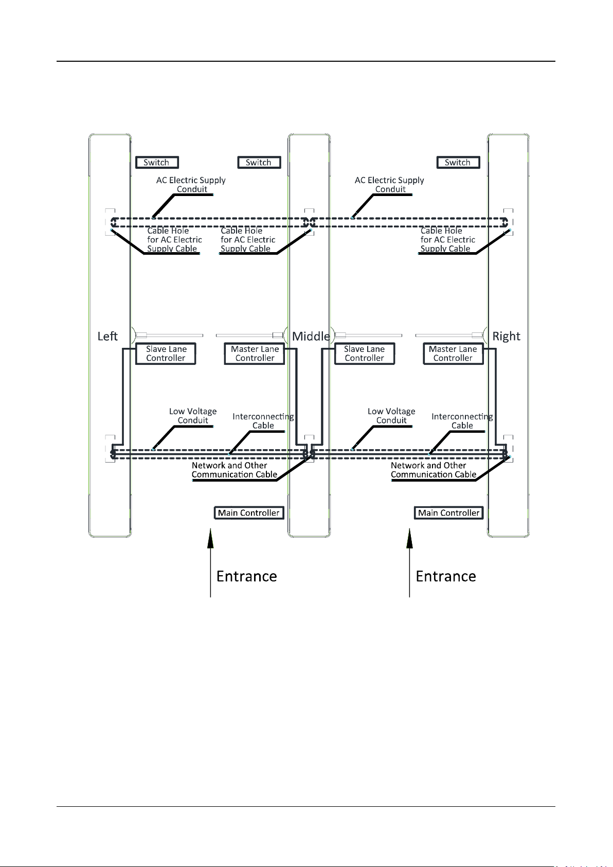
4.3.2 Wiring Face Recognition Terminal (Optional)
Notes:
The supplied interconnecting cable length is 3.75 m. If you need a longer one, ask our
technique supports or sales and purchase 5.5 m interconnecting cables.
The suggested inner diameters of the low voltage conduit should be larger than 30 mm.
If you want to bury both of the AC power cord and the low voltage cable at the entrance side,
the two cables should be in separated conduits to avoid interference.
If more peripherals are required to connect, you should increase the conduit diameter or bury
another conduit for the external cable.
The external AC power cord should be double-insulated.
The suggested network cable should be CAT5e or the network cable has better performance.
And the suggested network cable length should be less than 100 m. If the communication
length is more than 100 m, it is suggested to use optical fiber.
Swing Barrier·User Manual
21
4.4 Terminal Description
Purpose:
The lane controller contains master lane controller and slave lane controller, which controls the IR
beams, motor, and other components work.
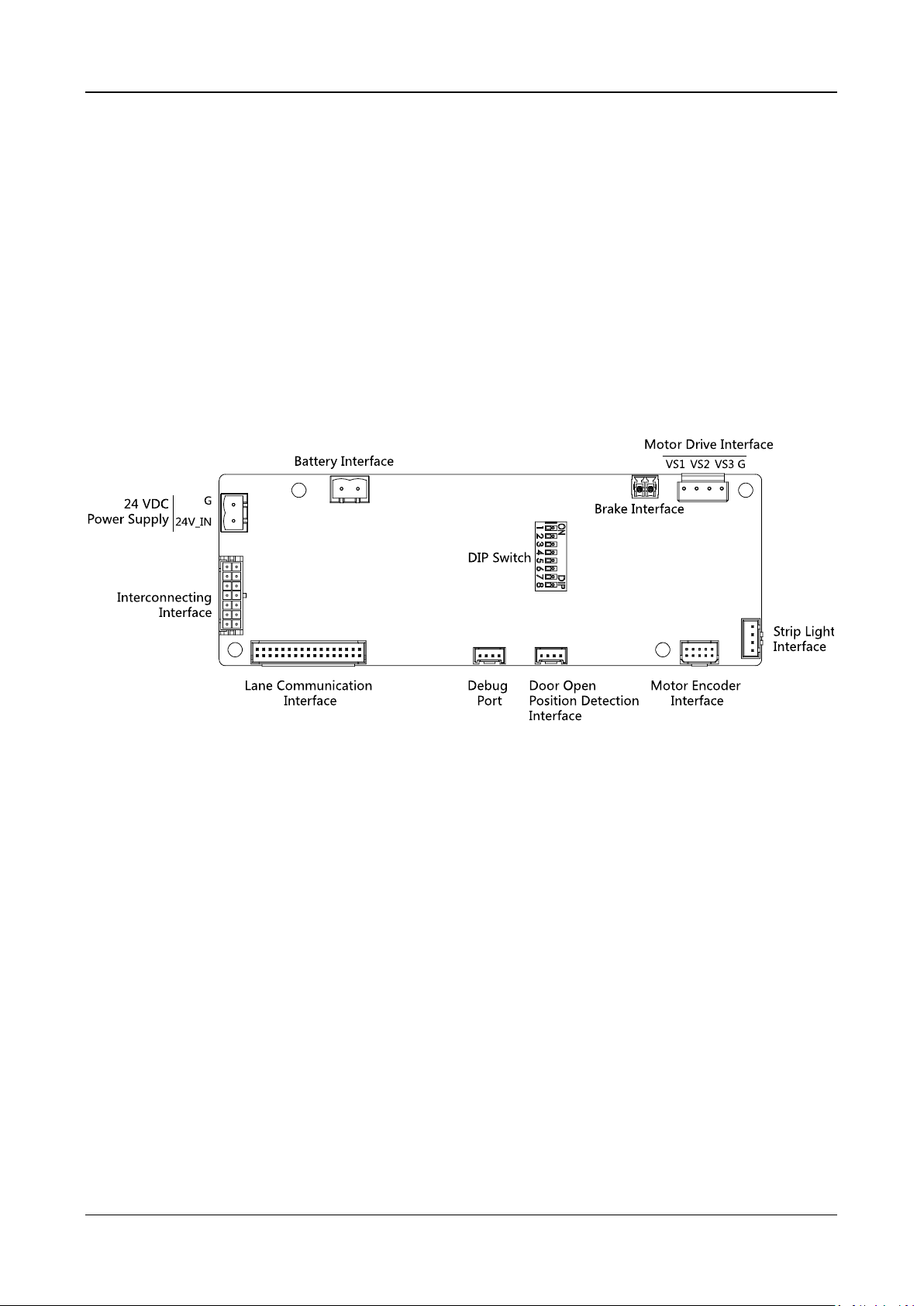
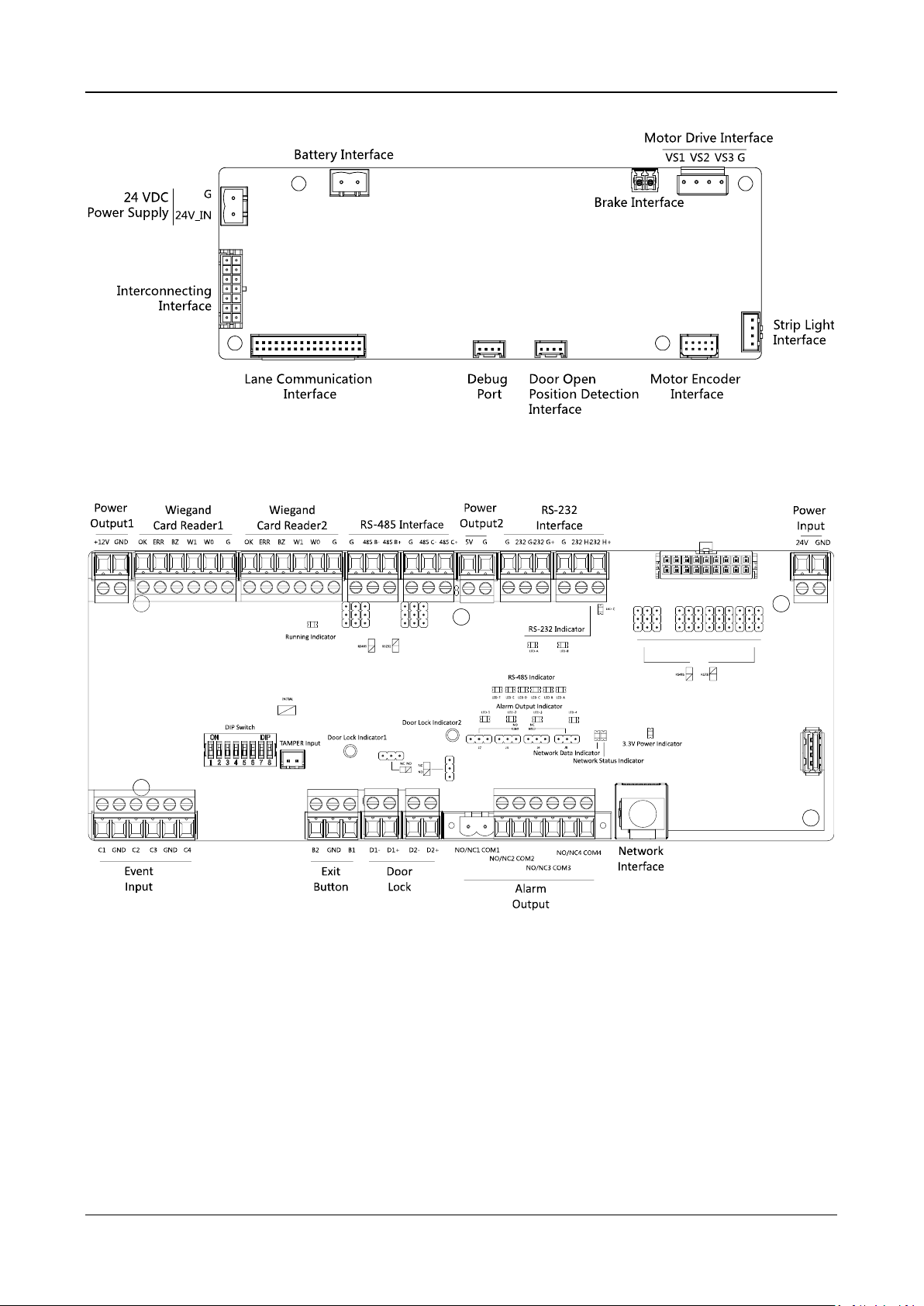
4.4.3 Master Control Board Terminal Description
Purpose:
The master lane control board contains power supply interface, battery interface, motor drive
interface, strip light interface, motor encoder interface, door open position detection interface,
debug port, lane communication interface, interconnecting interface, and DIP switch.
The picture displayed below is the master control board diagram.
4.4.4 Slave Control Board Terminal Description
Purpose:
The slave lane control board contains power supply interface, battery interface, motor drive
interface, strip light interface, motor encoder interface, door open position detection interface,
debug port, lane communication interface, and interconnecting interface.
Note: The master control board contains a DIP switch, while the slave control board not.
The picture displayed below is the slave control board diagram.
Swing Barrier·User Manual
22
4.4.5 Main Control Board Terminal Description

Swing Barrier·User Manual
23
Table 4-1 Main Control Board Terminal Description
Main Controlling Board Terminal Description
Power
Output1
+12V
Grounding
GND
Power Output
Wiegand
Card
Reader1
OK
Indicator of Card Reader Control Output (Invalid
Card Output)
ERR
Indicator of Card Reader Control Output (Valid
Card Output)
BZ
Card Reader Buzzer Control Output
W1
Wiegand Head Read Data Input Data1
W0
Wiegand Head Read Data Input Data0
GND
Grounding
Wiegand
Card Reader
2
OK
Indicator of Card Reader Control Output (Invalid
Card Output)
ERR
Indicator of Card Reader Control Output (Valid
Card Output)
BZ
Card Reader Buzzer Control Output
W1
Wiegand Head Read Data Input Data1
W0
Wiegand Head Read Data Input Data0
GND
Grounding
RS-485
Interface
GND
Grounding
RS-485 B-
Connect to Card Reader RS485-
RS-485 B+
Connect to Card Reader RS485+
GND
Grounding
RS-485 C-
Connect to Card Reader RS485-
RS-485 C+
Connect to Card Reader RS485+
Power
Output2
5V
5 VDC Power Output
GND
5 VDC Grounding
RS-232
Interface
GND
Grounding
RS-232 G-
Connect to Card Reader RS232-
RS-232 G+
Connect to Card Reader RS232+
GND
Grounding
RS-232 H-
Connect to Card Reader RS232-
RS-232 H+
Connect to Card Reader RS232+
Power Input
+12V
12 VDC Power Input
GND
12 VDC Grounding
Event Input
C1
Event Input
GND
Grounding
C2
Fire Input
C3
People Counting (Entrance)

Swing Barrier·User Manual
24
Main Controlling Board Terminal Description
GND
Grounding
C4
People Counting (Exit)
Exit Button
B2
Door 2 Signal Input
GND
Grounding
B1
Door 1 Signal Input
Door Lock
(Relay)
D1-
Door 1 Relay Output(Dry Contact)
D1+
D2-
Door 2 Relay Output(Dry Contact)
D2+
Alarm
Output
NO/NC1
Alarm Output Relay 1(Dry Contact)
COM1
NO/NC2
Alarm Output Relay 2(Dry Contact)
COM2
NO/NC3
Alarm Output Relay 3(Dry Contact)
COM3
NO/NC4
Alarm Output Relay 4(Dry Contact)
COM4
Network
Interface
LAN
Network Accessing
Notes:
The alarm input hardware interface is normally open by default. So only the normally open
signal is allowed. It can be linked to the buzzer of the card reader and access controller, and the
alarm relay output, open door relay output, and fire alarm output.
The DIP of RS485 card ID is set as 1 and 4 by default. 1 is for entering, and 4 is for exiting. Set the
DIP as 3 for connecting visitor card reader.
The Wiegand card reader 1 and 2 respectively refer to the entering and exiting card reader.
The alarm output supports relay output.
For any requirements, the door lock can control the door barrier status of the third party. D1
controls the barrier opening for entrance, while D2 controls the door opening for exit. For
details, see 5.5.1 Barrier Control Relay Output Mode.
C3 and C4 in the event input is people counting interface. C3 controls people counting for
entrance, while C4 controls people counting for exit. When the main control board detects
signals in C3 and C4, the people number will be accumulated. For detailed information about
people counting and people number, see Configuring People Counting Parameters in 7.2.6
Remote Configuration.
For detailed information about the DIP switch, see Appendix B DIP Switch Description.
Swing Barrier·User Manual
25
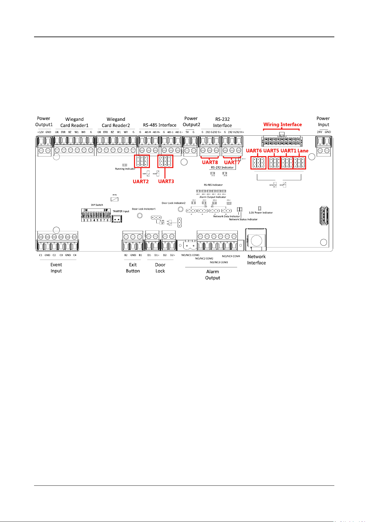
4.4.6 Main Control Board Serial Port ID Description
Purpose:
You can use the jumper cap on the main control board to switch the interface communication
mode. For details about switching between RS-232 and RS-485 communication type, see 5.4
Switching RS-485/RS-232 Mode.
According to the picture above, the RS-485 serial port corresponds to UART2 and UART3. RS-232
serial port is corresponded to UART7 and UART8. Wiring Interface is corresponded to UART1,
UART4, UART6, UART6, and Lane.
The main control board descriptions are as follows:
UART2/UART3 Jumper Cap:
Reserved serial port. Use the jumper cap to switch the serial
port communication mode. You can switch between the
RS-485 communication mode and the RS-232
communication mode. By default, it is in RS-485
communication mode.
UART6 Jumper Cap:
Use the jumper cap to switch the serial port communication
mode with the slave lane controller. You can switch between
the RS-232 communication mode and the RS-485
communication mode. By default, it is in RS-232
communication mode.
UART5 Jumper Cap:
Use the jumper cap to switch the serial port communication
mode with the slave lane controller. You can switch between
the RS-484 communication mode and the RS-232
communication mode. By default, it is in RS-485
communication mode.

Swing Barrier·User Manual
26
UART1 Jumper Cap:
Use the jumper cap to switch the serial port communication
mode with the master lane controller. You can switch
between the RS-484 communication mode and the RS-232
communication mode. By default, it is in RS-485
communication mode.
Lane:
Use the jumper cap to switch the serial port communication
mode with the lane controller. By default, the interface is
wired and it is in RS-485 communication mode.
If wiring other controllers (compatible with Hikvision
communication protocol), use the jumper cap to switch
between RS-485 and RS-232 communication mode.
UART4:
The serial port is in the wiring interface according to the
picture above, which has a fixed RS-232 communication
mode to communicate with the master lane controller. It
contains no jumper cap and cannot change the
communication mode.
UART7/UART8:
Reserved serial port. The serial port has a fixed RS-232
communication mode. It contains no jumper cap and cannot
change the communication mode. It can connect QR code
scanner, card recycler, and text screen.
The reserved interface positions in the swing barrier and their corresponded UART No. are as
follows:

Swing Barrier·User Manual
27
4.4.7 RS-485 Wiring
Notes:
There are five RS-485 interfaces, which are for connecting ID card reader, IC card reader, QR
code scanner, fingerprint and card reader, card recycler, text screen, fingerprint reader, and face
recognition terminal. Take the wiring of RS-485 card reader as an example.
For details about text screen, see Configuring Screen Parameters in 7.2.6 Remote Configuration.
4.4.8 RS-232 Wiring
Note: There are three RS-232 interfaces (UART4, UART7, and UART8). UART7 and UART8 can
connect QR code scanner, card recycler, and text screen, while UART4 can connect QR code
scanner, card recycler, text screen, and face recognition terminal. For details about text screen, see
Configuring Screen Parameters in 7.2.6 Remote Configuration.
Take the wiring of face recognition terminal as an example.

Swing Barrier·User Manual
28
4.4.9 Wiegand Wiring
Note: You must connect the OK/ERR/BZ if using access controller to control the LED and buzzer of
the Wiegand card reader.

Swing Barrier·User Manual
29
4.4.10 Barrier Control Wiring
Purpose:
By default, the barrier has connected with the main control board. The lane control board can
control the barrier status. If possible, the device can connect with a third party lane control board
to control the third party barriers. Interface D1 controls barrier opening for entrance, while
interface D2 controls barrier opening for exit.
Entering Wiring
Exiting Wiring

Swing Barrier·User Manual
30
4.4.11 Alarm Output Wiring
Note: For details about changing the relay output status via the jumper cap, see 5.5.2 Alarm Relay
Output Mode (NO/NC).
4.5 Wiring Lithium Battery (Optional)
Purpose:
The lithium battery supplies power for master lane control board and slave lane control board
when the device is powered off.
Notes:
RISK OF EXPLOSION IF BATTERY IS REPLACED BY AN INCORRECT TYPE.
DISPOSE OF USED BATTERIES ACCORDING TO THE INSTRUCTIONS.
Before you start:
Ask our technique support and sales and purchase for the lithium battery.
Steps:
1. Install lithium batteries.
1) Remove the screws on the battery component to disassamle the battery component.

Swing Barrier·User Manual
31
2) Put the lithium battery inside the component.
3) Tear the double sided adhesive tape and secure the components on the pedestal by the
screws.
2. Connect the battery connecter to the battery interface on the lane control board.
Note: There are battery interfaces on both of the master lane control board and slave lane
control board.

Swing Barrier·User Manual
32

Swing Barrier·User Manual
33
Chapter 5 Device Settings
Purpose:
After installation and wiring completed, you should set the barriers closed position (study mode)
before entering the work mode.
You can also set the test mode, normal mode, passing mode and memory mode, pair the keyfob,
initialize the hardware, switching between RS-485 communication mode and RS-232
communication mode, and view relay output NO/NC diagram by setting the DIP switch.
Study Mode: The barrier will learn the closed position.
Normal Mode: The device will work properly. The barrier position configured in study mode is
the closed position when the device is working normally.
Test Mode: Test mode is the same as the normal mode except that the device cannot report
the alarm or the event to the center.
Passing Mode: There are 9 passing modes, including controlled bi-direction, controlled
entrance and prohibited exit, controlled entrance and free exit, free bi-direction, free entrance
and controlled exit, free entrance and prohibited exit, prohibited bi-direction, prohibited
entrance and free exit.
Memory Mode: By default, the memory mode is enabled. When multiple cards are swiped and
authenticated, it allows multiple persons passing through the lane. When it counts the passing
people number is equal to the card swiped times, or no person passing through the lane after
the last person passing, the barriers will be closed.
Note: You can control the action of swiping card to open the barrier in alarm area via client
software. You can also set the DIP switch to control the entrance and exit controlling type, keyfob
pairing, etc. For details about the DIP switch value, see Appendix B DIP Switch Description.
5.1 Setting Closed Position
Purpose:
Enter the study mode through DIP switching to set the closed position of the device barrier.
Steps:
1. Set The No.1 and No.2 switches of the 8-digit DIP Switch on the main controller by referring the
following figure to enter the study mode.
2. Adjust the closed position of the barrier.
3. Power on the device.
The device will remember the current position (closed position) automatically.
4. Power off the device.
5. Set the No.1 and No.2 switches of the 8-digit DIP Switch on the main controller by referring to
the following figure.

Swing Barrier·User Manual
34
6. Power on the device again.
The barrier will open automatically and turns back to the closed position. At this circumstance,
the device enters the normal mode.
Note: For details about the DIP switch value and meaning, see Appendix B DIP Switch
Description.
5.2 Pairing Keyfob (Optional)
Purpose:
Pair the keyfob to the device through DIP switch to open/close the barrier remotely.
Note: for details about the keyfob’s operations, see the related user manual.
Before you start:
Ask our technique supports or sales and buy the keyfob.
Steps:
1. Power off the swing barrier.
2. Set the No.4 switch of the 8-digit DIP Switch on the main control board according to the figure
below.
3. Power on the swing barrier and it will enter the keyfob pairing mode.
4. Hold the Close button for more than 10 seconds.
The keyfob’s indicator will flash twice if the pairing is completed.
Notes:
You can also pair the keyfob via the client software. For details, see Managing keyfob in
7.2.6 Remote Configuration.
Only one swing barrier can pair the keyfob. If multiple swing barriers are in the keyfob
pairing mode, the keyfob will select only one of them to pair.
For details about DIP switch value and meaning, see Appendix B DIP Switch Description.
5.3 Initializing Device
Steps:
1. Remove the JP11 jumper cap.
2. Disconnect the power and reboot the device. The device buzzer buzzes a long beep.
3. When the beep stopped, plug the jumper cap back.
4. Disconnect the power and reboot the device.
Note: The initializing of the device will restore all the parameters to the default setting and all
the device events are deleted.

Swing Barrier·User Manual
35
5.4 Switching RS-485/RS-232 Mode
Take the UART2 and UART3 on the main control board as an example. If the Jumper cap’s position
is like the picture displayed below. (The black part is the jumper cap.) The serial port is in RS-485
communication mode.
If the Jumper cap’s position is like the picture displayed below. (The black part is the jumper cap.)
The serial port is in RS-232 communication mode.
5.5 Switching Relay Output Mode (NO/NC)
5.5.1 Barrier Control Relay Output Mode
The pins of the barrier control relay on the main control board is as below:
The jumper cap’s position of barrier opening for entrance (NO) is as below:
The jumper cap’s position of barrier opening for exit (NO) is as below:
The jumper cap’s position of barrier closing for entrance (NC) is as below:
The jumper cap’s position of barrier closing for exit (NC) is as below:

Swing Barrier·User Manual
36
5.5.2 Alarm Relay Output Mode (NO/NC)
Alarm Relay Output Mode (NO):
Alarm Relay Output Mode (NC):
Swing Barrier·User Manual
37
Chapter 6 Device Activation
Purpose:
You are required to activate the terminal first before using it.
Activation via SADP, and activation via client software are supported.
The default values of the control terminal are as follows.
The default IP address: 192.0.0.64.
The default port No.: 8000.
The default user name: admin.
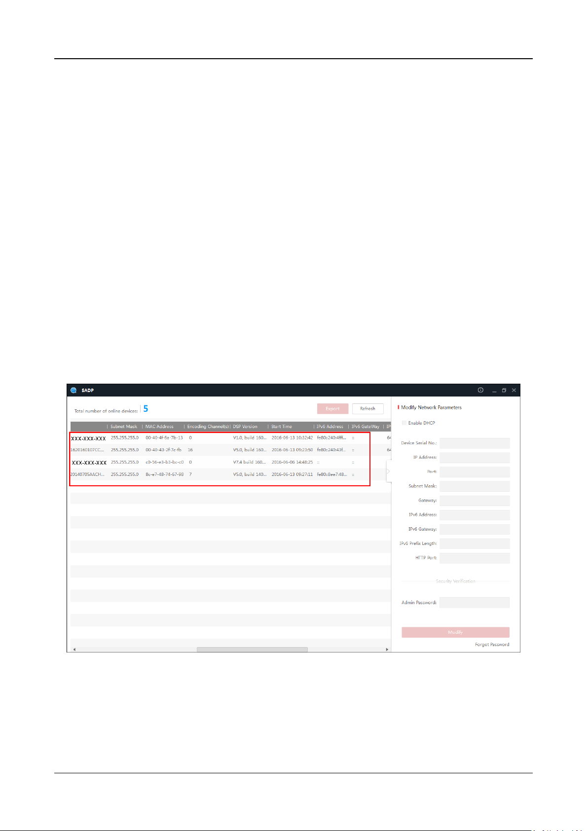
6.1 Activating via SADP Software
SADP software is used for detecting the online device, activating the device, and resetting the
password.
Get the SADP software from the supplied disk, and install the SADP according to the prompts.
Follow the steps to activate the control panel.
Steps:
1. Run the SADP software to search the online devices.
2. Check the device status from the device list, and select an inactive device.
3. Create a password and input the password in the password field, and confirm the password.

Swing Barrier·User Manual
38
STRONG PASSWORD RECOMMENDED– We highly recommend you create a strong
password of your own choosing (using a minimum of 8 characters, including upper case
letters, lower case letters, numbers, and special characters) in order to increase the
security of your product. And we recommend you reset your password regularly,
especially in the high security system, resetting the password monthly or weekly can
better protect your product.
4. Click Activate to save the password.
5. Check the activated device. You can change the device IP address to the same network
segment with your computer by either modifying the IP address manually or checking the
checkbox of Enable DHCP.
6. Input the password and click the Modify button to activate your IP address modification.
6.2 Activating via Client Software
The client software is versatile video management software for multiple kinds of devices.
Get the client software from the supplied disk, and install the software according to the prompts.
Follow the steps to activate the control panel.
Steps:
1. Run the client software and the control panel of the software pops up, as shown in the figure
below.

Swing Barrier·User Manual
39
2. Click Device Management to enter the Device Management interface.
3. Check the device status from the device list, and select an inactive device.
4. Check the device status from the device list, and select an inactive device.
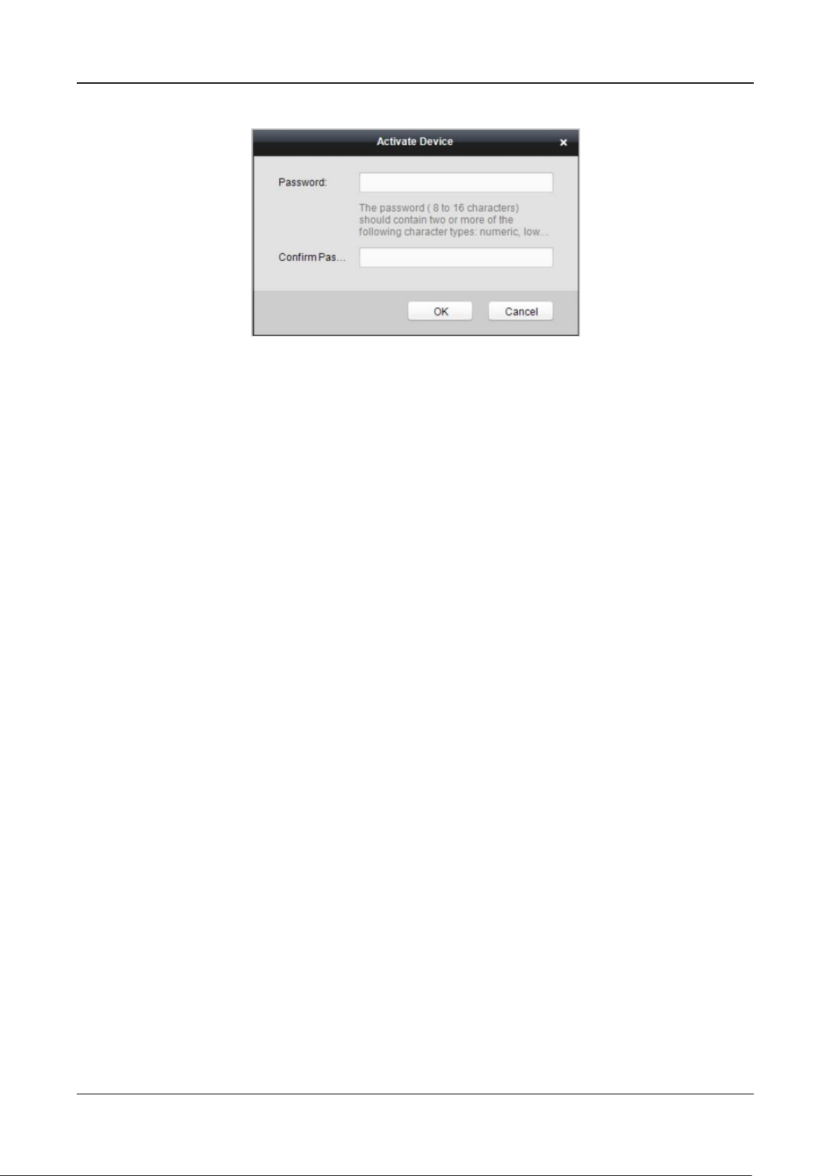
5. Click the Activate button to pop up the Activation interface
6. In the pop-up window, create a password in the password field, and confirm the password.
STRONG PASSWORD RECOMMENDED– We highly recommend you create a strong
password of your own choosing (using a minimum of 8 characters, including upper
case letters, lower case letters, numbers, and special characters) in order to increase
the security of your product. And we recommend you reset your password regularly,
especially in the high security system, resetting the password monthly or weekly can
better protect your product.
Swing Barrier·User Manual
40
7. Click OK button to start activation.
8. Click the Modify Netinfor button to pop up the Network Parameter Modification interface.
9. Change the device IP address to the same network segment with your computer by either
modifying the IP address manually.
10. Input the password and click the OK button to save the settings.

Swing Barrier·User Manual
41
Chapter 7 Client Operation
You can set and operate the access control devices via the client software. This chapter will
introduce the access control device related operations in the client software. For integrated
operations, refer to User Manual of iVMS-4200 Client Software.
7.1 Function Module
Control Panel of iVMS-4200:
7.2 Access Control Management
Purpose:
The Access Control module is applicable to access control devices and video intercom. It provides
multiple functionalities, including person and card management, permission configuration, access
control status management, video intercom, and other advanced functions.
You can also set the event configuration for access control and display access control points and
zones on E-map.
Note: For the user with access control module permissions, the user can enter the Access Control
module and configure the access control settings.
Click in the control panel, and check Access Control to add the Access Control module to
the control panel.
Click to enter the Access Control module.

Swing Barrier·User Manual
42
Before you start:
For the first time opening the Access Control module, the following dialog will pop up and you are
required to select the scene according to the actual needs.
Non-residence: You can set the attendance rule when adding person, while set the access control
parameters.
Residence: You cannot set the attendance rule when adding person.
Note: Once the scene is configured, you cannot change it later.
7.2.1 Adding Access Control Device
Click in the Access Control module to enter the following interface.

Swing Barrier·User Manual
43
Note: After adding the device, you should check the device arming status in Tool – Device Arming
Control. If the device is not armed, you should arm it, or you will not receive the real-time events
via the client software. For details about device arming control, refer 7.10 Arming Control.
Adding Online Device
Purpose:
The active online devices in the same local subnet with the client software will be displayed on the
Online Device area. You can click the Refresh Every 60s button to refresh the information of the
online devices.
Note: You can click to hide the Online Device area.
Steps:
1. Select the devices to be added from the list.
Note: For the inactive device, you need to create the password for it before you can add the
device properly.
2. Click Add to Client to open the device adding dialog box.
3. Input the required information.
Nickname: Edit a name for the device as you want.
Address: Input the device’s IP address. The IP address of the device is obtained automatically in
this adding mode.
Port: Input the device port No. The default value is 8000.
User Name: Input the device user name. By default, the user name is admin.
Password: Input the device password.

Swing Barrier·User Manual
44
STRONG PASSWORD RECOMMENDED– We highly recommend you create a strong password
of your own choosing (using a minimum of 8 characters, including upper case letters, lower
case letters, numbers, and special characters) in order to increase the security of your product.
And we recommend you reset your password regularly, especially in the high security system,
resetting the password monthly or weekly can better protect your product.
4. Optionally, check the Export to Group checkbox to create a group by the device name.
You can import all the channels of the device to the corresponding group by default.
Note: iVMS-4200 also provides a method to add the offline devices.
1) Check the Add Offline Device checkbox.
2) Input the required information, including the device channel number and alarm input
number.
3) Click Add.
When the offline device comes online, the software will connect it automatically.
5. Click Add to add the device.
Adding Multiple Online Device
If you want to add multiple online devices to the client software, click and hold Ctrl key to
select multiple devices, and click Add to Client to open the device adding dialog box. In the
pop-up message box, enter the user name and password for the devices to be added.
Adding All Online Devices
If you want to add all the online devices to the client software, click Add All and click OK in the
pop-up message box. Then enter the user name and password for the devices to be added.

Swing Barrier·User Manual
45
Adding Devices by IP or Domain Name
Steps:
1. Click Add to open the device adding dialog box.
2. Select IP/Domain as the adding mode.
3. Input the required information.
Nickname: Edit a name for the device as you want.
Address: Input the device’s IP address or domain name.
Port: Input the device port No. The default value is 8000.
User Name: Input the device user name. By default, the user name is admin.
Password: Input the device password.
STRONG PASSWORD RECOMMENDED– We highly recommend you create a strong password
of your own choosing (using a minimum of 8 characters, including upper case letters, lower
case letters, numbers, and special characters) in order to increase the security of your product.
And we recommend you reset your password regularly, especially in the high security system,
resetting the password monthly or weekly can better protect your product.
4. Optionally, check the Export to Group checkbox to create a group by the device name.
You can import all the channels of the device to the corresponding group by default.
Note: iVMS-4200 also provides a method to add the offline devices.
1) Check the Add Offline Device checkbox.
2) Input the required information, including the device channel number and alarm input
number.
3) Click Add.
When the offline device comes online, the software will connect it automatically.
5. Click Add to add the device.

Swing Barrier·User Manual
46
Adding Devices by IP Segment
Steps:
1. Click Add to open the device adding dialog box.
2. Select IP Segment as the adding mode.
3. Input the required information.
Start IP: Input a start IP address.
End IP: Input an end IP address in the same network segment with the start IP.
Port: Input the device port No. The default value is 8000.
User Name: Input the device user name. By default, the user name is admin.
Password: Input the device password.
STRONG PASSWORD RECOMMENDED– We highly recommend you create a strong password
of your own choosing (using a minimum of 8 characters, including upper case letters, lower
case letters, numbers, and special characters) in order to increase the security of your product.
And we recommend you reset your password regularly, especially in the high security system,
resetting the password monthly or weekly can better protect your product.
4. Optionally, check the Export to Group checkbox to create a group by the device name.
You can import all the channels of the device to the corresponding group by default.
Note: iVMS-4200 also provides a method to add the offline devices.
1) Check the Add Offline Device checkbox.
2) Input the required information, including the device channel number and alarm input
number.
3) Click Add.
When the offline device comes online, the software will connect it automatically.
5. Click Add.
You can add the device which the IP address is between the start IP and end IP to the device
list.

Swing Barrier·User Manual
47
Adding Devices by Hik-Connect Domain
Purpose:
You can add the devices connected via Hik-Connect by inputting the Hik-Connect account and
password.
Before you start:
Add the devices to Hik-Connect account via iVMS-4200, iVMS-4500 Mobile Client, or Hik-Connect
first. For details about adding the devices to Hik-Connect account via iVMS-4200, refer to the User
Manual of iVMS-4200 Client Software.
Add Single Device
Steps:
1. Click Add to open the device adding dialog.
2. Select Hik-Connect Domain as the adding mode.
3. Select Single Adding.
4. Input the required information.
Nickname: Edit a name for the device as you want.
Device Serial No.: Input the device serial No.
User Name: Input the device user name. By default, the user name is admin.
Password: Input the device password.
STRONG PASSWORD RECOMMENDED– We highly recommend you create a strong password
of your own choosing (using a minimum of 8 characters, including upper case letters, lower
case letters, numbers, and special characters) in order to increase the security of your product.
And we recommend you reset your password regularly, especially in the high security system,
resetting the password monthly or weekly can better protect your product.
Hik-Connect Account: Input the Hik-Connect account.
Hik-Connect Password: Input the Hik-Connect password.
5. Optionally, check the Export to Group checkbox to create a group by the device name.

Swing Barrier·User Manual
48
You can import all the channels of the device to the corresponding group by default.
6. Click Add to add the device.
Add Devices in Batch
Steps:
1. Click Add to open the device adding dialog.
2. Select Hik-Connect Domain as the adding mode.
3. Select Batch Adding.
4. Input the required information.
Hik-Connect Account: Input the Hik-Connect account.
Hik-Connect Password: Input the Hik-Connect password.
5. Click Get Device List to show the devices added to Hik-Connect account.

Swing Barrier·User Manual
49
6. Check the checkbox(es) to select the device as desired.
7. Input the user name and password for the devices to be added.
8. Optionally, check the Export to Group checkbox to create a group by the device name.
You can import all the channels of the device to the corresponding group by default.
9. Click Add to add the devices.
Adding Devices by Serial Port
Purpose:
You can add access control device connected via serial port.
Steps:
1. Click Add to open the device adding dialog box.
2. Select Serial Port as the adding mode.
3. Input the required information.
Nickname: Edit a name for the device as you want.
Serial Port No.: Select the device’s connected serial port No.

Swing Barrier·User Manual
50
Baud Rate: Input the baud rate of the access control device.
DIP: Input the DIP address of the device.
4. Optionally, check the Export to Group checkbox to create a group by the device name.
You can import all the channels of the device to the corresponding group by default.
Note: iVMS-4200 also provides a method to add the offline devices.
1) Check the Add Offline Device checkbox.
2) Input the required information, including the device channel number and alarm input
number.
3) Click Add.
When the offline device comes online, the software will connect it automatically.
5. Click Add to add the device.
Adding Devices by IP Server
Steps:
1. Click Add to open the device adding dialog box.
2. Select IP Server as the adding mode.
3. Input the required information.
Nickname: Edit a name for the device as you want.
Server Address: Input the IP address of the PC that installs the IP Server.
Device ID: Input the device ID registered on the IP Server.
User Name: Input the device user name. By default, the user name is admin.
Password: Input the device password.
STRONG PASSWORD RECOMMENDED– We highly recommend you create a strong password
of your own choosing (using a minimum of 8 characters, including upper case letters, lower
case letters, numbers, and special characters) in order to increase the security of your product.
And we recommend you reset your password regularly, especially in the high security system,
resetting the password monthly or weekly can better protect your product.

Swing Barrier·User Manual
51
4. Optionally, check the Export to Group checkbox to create a group by the device name.
You can import all the channels of the device to the corresponding group by default.
Note: iVMS-4200 also provides a method to add the offline devices.
1) Check the Add Offline Device checkbox.
2) Input the required information, including the device channel number and alarm input
number.
3) Click Add.
When the offline device comes online, the software will connect it automatically.
5. Click Add to add the device.
Importing Devices in Batch
Purpose:
The devices can be added to the software in batch by inputting the device information in the
pre-defined CSV file.
Steps:
1. Click Add to open the device adding dialog box.
2. Select Batch Import as the adding mode.
3. Click Export Template and save the pre-defined template (CSV file) on your PC.
4. Open the exported template file and input the required information of the devices to be added
on the corresponding column.
Nickname: Edit a name for the device as you want.
Adding Mode: You can input 0, 2, 3, 4, 5, or 6 which indicated different adding modes. 0
indicates that the device is added by IP address or domain name; 2 indicates that the
device is added via IP server; 3 indicates that the device is added via HiDDNS; 4 indicates
that the device is added via EHome protocol; 5 indicates that the device is added by serial
port; 6 indicates that the device is added via Hik-Connect Domain.
Address: Edit the address of the device. If you set 0 as the adding mode, you should input
the IP address or domain name of the device; if you set 2 as the adding mode, you should
input the IP address of the PC that installs the IP Server; if you set 3 as the adding mode,

Swing Barrier·User Manual
52
you should input www.hik-online.com.
Port: Input the device port No.. The default value is 8000.
Device Information: If you set 0 as the adding mode, this field is not required; if you set 2
as the adding mode, input the device ID registered on the IP Server; if you set 3 as the
adding mode, input the device domain name registered on HiDDNS server; if you set 4 as
the adding mode, input the EHome account; if you set 6 as the adding mode, input the
device serial No.
User Name: Input the device user name. By default, the user name is admin.
Password: Input the device password.
STRONG PASSWORD RECOMMENDED– We highly recommend you create a strong password
of your own choosing (using a minimum of 8 characters, including upper case letters, lower
case letters, numbers, and special characters) in order to increase the security of your product.
And we recommend you reset your password regularly, especially in the high security system,
resetting the password monthly or weekly can better protect your product.
Add Offline Device: You can input 1 to enable adding the offline device, and then the
software will automatically connect it when the offline device comes online. 0 indicates
disabling this function.
Export to Group: You can input 1 to create a group by the device name (nickname). All the
channels of the device will be imported to the corresponding group by default. 0 indicates
disabling this function.
Channel Number: If you set 1 for Add Offline Device, input the channel number of the
device. If you set 0 for Add Offline Device, this field is not required.
Alarm Input Number: If you set 1 for Add Offline Device, input the alarm input number of
the device. If you set 0 for Add Offline Device, this field is not required.
Serial Port No.: If you set 5 as the adding mode, input the serial port No. for the access
control device.
Baud Rate: If you set 5 as the adding mode, input the baud rate of the access control
device.
DIP: If you set 5 as the adding mode, input the DIP address of the access control device.
Hik-Connect Account: If you set 6 as the adding mode, input the Hik-Connect account.
Hik-Connect Password: If you set 6 as the adding mode, input the Hik-Connect password.
5. Click and select the template file.
6. Click Add to import the devices.
The devices will be displayed on the device list for management after added successfully. You can
check the resource usage, HDD status, recording status, and other information of the added
devices on the list.
Click Refresh All to refresh the information of all added devices. You can also input the device
name in the filter field for search.

Swing Barrier·User Manual
53
7.2.2 Viewing Device Status
In the device list, you can select the device and then click Device Status button to view its status.
Note: The interface may different from the picture displayed above. Refer to the actual interface
when adopting this function.
Status Name
Description
Door Status
View the device door’s status.
Host Status
View the device host’s status, including the device power supply
status, anti-passing back status, host tampering status, etc.
Card Reader Status
View the card reader’s status, including the online status, the
tampering status, and the authentication method.
Alarm Input Status
View the alarm input’s status.
Alarm Output Status
View the alarm output’s status.
Event Sensor Status
View the event sensor’s status.
Arming Status
View the arming device’s IP address and its arming type.
DIP Information
View the device local DIP information.
General Status
View the device general status, including the BUS synchronization
status, IR people counting for entrance, authenticated people
counting for entrance, etc.
Active Infrared Intrusion
Detector Status
View the status of active infrared intrusion detector, receiving
board, etc.
Component Status
View the device components’ status, including the status of the
motor sensor, brake status, etc.

Swing Barrier·User Manual
54
7.2.3 Editing Basic Information
Purpose:
After adding the access control device, you can edit the device basic information.
Steps:
1. Select the device in the device list.
2. Click Modify to pop up the modifying device information window.
3. Click Basic Information tab to enter the Basic Information interface.
4. Edit the device information, including the adding mode, the device name, the device IP address,
port No., user name, and the password.
7.2.4 RS-485 Settings
Purpose:
You can set the RS-485 parameters including the serial port, the baud rate, the data bit, the stop
bit, the parity type, the communication mode, and the working mode.
Note: The RS-485 Settings should be supported by the device.
Steps:
1. Select the device in the device list, and click Modify to pop up the modifying device
information window.
2. Click RS-485 Settings tab to enter the RS-485 settings interface.

Swing Barrier·User Manual
55
2. Select the serial No. of the port from the dropdown list to set the RS-485 parameters.
3. Set the baud rate, data bit, the stop bit, parity type, communication mode, and working mode
in the dropdown list.
4. Click Save to save the settings and the configured parameters will be applied to the device
automatically.
Note: After changing the working mode, the device will be rebooted. A prompt will be popped up
after changing the working mode.
7.2.5 Authenticating M1 Card Encryption
Before you start:
You should use the specified Hikvision card enrollment station to issue card. For details, refer to
Adding Person (Card) in Chapter 7.4.1 Adding Person.
Purpose:
The M1 Card Encryption function increases the authentication security level, which should be
applied together with the card enrollment station of our company via the client software or the
web client. After issuing the card, you can set the M1 card encryption function on the controller.
Note: The function should be supported by the access control device and the card reader.
Steps:
1. Select the device in the device list, and click Modify to pop up the modifying device
information window.
2. Click M1 Card Encryption tab to enter the M1 Card Encryption interface.
3. In the M1 Card Encryption interface, check Enable checkbox to enable the M1 card encryption
function.
4. Set the sector ID.
5. Click Save to save the settings.
Note: The sector ID ranges from 1 to 100.

Swing Barrier·User Manual
56
7.2.6 Remote Configuration
Purpose:
In the device list, select the device and click Remote Configuration button to enter the remote
configuration interface. You can set the detailed parameters of the selected device.
Checking Device Information
Steps:
1. In the device list, you can click Remote Configuration to enter the remote configuration
interface.
2. Click System -> Device Information to check the device basic information and the device
version information.
Editing Device Name
In the Remote Configuration interface, click System -> General to configure the device name and
overwrite record files parameter. Click Save to save the settings.

Swing Barrier·User Manual
57
Editing Time
Steps:
1. In the Remote Configuration interface, click System -> Time to configure the time zone.
2. (Optional) Check Enable NTP and configure the NTP server address, the NTP port, and the
synchronization interval.
3. (Optional) Check Enable DST and configure the DST star time, end time and the bias.
4. Click Save to save the settings.
Setting System Maintenance
Purpose:
You can reboot the device remotely, restore the device to default settings, import configuration file,
upgrade the device, etc.
Steps:
1. In the Remote Configuration interface, click System -> System Maintenance.
2. Click Reboot to reboot the device.
Or click Restore Default Settings to restore the device settings to the default ones, excluding
the IP address.
Or click Restore All to restore the device parameters to the default ones. The device should be
activated after restoring.
Note: The configuration file contains the device parameters.
3. You can also remote upgrade the device.
1) In the Remote Upgrade part, select Controller Upgrade File, Card Reader Upgrade File or
Upgrade File of Lange Controller from the drop down list.
2) Upgrade File of Lange Controller from the drop down list.
Controller Upgrade File: Upgrade access controller.
Card Reader Upgrade File: Upgrade card reader. Only card readers connected via RS-485
can be upgraded remotely.
Upgrade File of Lane Controller: Select master lane controller or slave lane controller to
upgrade.

Swing Barrier·User Manual
58
3) Click to select the upgrade file.
4) Click Upgrade to start upgrading.
Setting RS-485 Parameters
You can set the RS-485 parameters in this page.
Notes:
Supports 9 peripherals: ID card reader, IC card reader, QR code scanner, fingerprint and card
reader ,text screen, card recycler, fingerprint reader, and ID card identification terminal.
If selecting ID card reader, QR code scanner, card recycler, text screen, or fingerprint reader as
the peripheral, you should set the accessing direction.
If selecting IC card reader or fingerprint reader as the external device, you should set accessing
direction by setting the DIP switch.
The system supports 3 authentication centers: Device, Client and Unlimited Access.

Swing Barrier·User Manual
59
If you select Unlimited Access, the swing barrier will open the door immediately after any
user’s authentication via the configured peripheral (except for the face recognition terminal)
on this page. If connecting a face recognition terminal, the person should be added to the face
picture library, or the function cannot be operated.
The authentication center type Client is mainly adopted by developers of the third party
software.
Managing Network User
Steps:
1. In the Remote Configuration interface, click System -> User -> Network User.
2. Click Add to add the user (Do not support by the elevator controller.).
Or select a user in the user list and click Edit to edit the user. You are able to edit the user
password, the IP address, the MAC address and the user permission. Cilck OK to confirm
editing.
Managing Remote Control User
Purpose:
You can match the remote control’s code in this page. After the code is matched, you can control
the device by the remote control.
Steps:

Swing Barrier·User Manual
60
1. In the Remote Configuration interface, click System -> User -> Remote Control User.
2. Click Add to add the user.
3. Check Enable in the pop-up window and set the remote control’s serial No.
4. (Optional) Enable the Remian Open Status of the swing barrier.
Note: If enabling this function, after the remote control matching completed, you can control
the baffle remaining open by using the remote control.
5. Set the door open direction.
6. Click OK to save the settings.
Note: You can add up to 32 remote control users.
Setting Security
Purpose:
You can set the security parameters when logging in the device.
Steps:
1. Click System -> Security.
2. Select the encryption mode in the dropdown list.
You can select Compatible Mode or Encryption Mode.
3. Click Save to save the settings.
Configuring Passing Parameters
Purpose:
You can set the passing parameters for a person to pass through the device.
Click System -> Passing Settings and set the parameters. Click Save to save the settings.
The parameters descriptions are as follows:
Delayed Time Duration When
Closing Barrier:
Set the delayed time duration for barrier closing. The
barrier will be closed after the configured delayed
time duration.
Max. Intrusion Duration:
If a person has entered the lane or passed through the

Swing Barrier·User Manual
61
lane for more than the configured time duration, an
alarm will be triggered. 0 represents the function is
disabled.
Note: The suggested minimum detection time
duration is 2s.
Overstayed Time Duration:
If the device detects persons or things staying in the
lane for more than the configured time duration, an
alarm will be triggered.
Max. IR Obstructed Duration:
Set the maximum time duration for the obstruction of
the IR light. If the IR light is obstructed for more than
the configured time duration, the alarm will be
triggered. 0 represents the function is disabled.
Configuring Screen Parameters
Purpose:
The device can connect to a text screen. You can set the display parameters on this page.
Click System -> Screen Configuration and set the parameters. Click Save to save the settings.
Note: For better performance, we suggest you to use the default parameters.
The parameters descriptions are as follows:
Screen Position:
Select the screen’s position on the device.
If select Exit from the drop-down list, the screen will be installed at
the exit position of the device.
Screen Model:
Select the screen model from the drop-down list.
Font Size:
Select the text font size in the screen.
Text Orientation:
Select the text orientation on the screen.
Line Spacing:
Set the space between two lines.
Word Spacing:
Set the space between two words.
Initial Position:
Set the first character’s position displayed on the screen.

Swing Barrier·User Manual
62
Configuring People Counting Parameters
Purpose:
You can set the people counting’s parameters and after the configuration.
Click System -> People Counting and set the parameters. Click Save to save the settings.
The parameters descriptions are as follows:
Clear People Number:
Click Clear and the counted people number will be restored to zero.
Device People Counting:
Click Enable or Disable to enable or disable the people counting
function.
Offline People Counting
on Client:
Click Enable or Disable to enable or disable function of the offline
people counting on the client.
If enabling the function and if the device is offline, the device will
continue counting the people and the number will be stored in the
device. When the device is online, the client will read the updated
number from the device automatically.
People Counting Type:
You can select from Invalid, By IR Detection, and By Authentication
Number.
None:
The device will not count people.
If the device people counting function is
enabled, the people counting function is still
disabled.
By IR Detection:
The device will count the people who passing
through the device depending on the IR
detection.
By Authentication
Number:
The device will count the people who
authenticating on the device.
The failed authentication will also count as
once.

Swing Barrier·User Manual
63
Configuring Network Parameters
Click Network -> General. You can configure the NIC type, the IPv4 address, the subnet mask (IPv4),
the default gateway (IPv4), MTU address, and the device port. Click Save to save the settings.
Configuring Advanced Network
Click Network -> Advanced Settings. You can configure the DNS 1 IP address and the DNS 2 IP
address. Click Save to save the settings.
Configuring Relay Parameters
Purpose:
Set the main controller alarm output’s relay parameters.
Steps:
1. Click Alarm -> Trigger.
You can view the trigger parameters.

Swing Barrier·User Manual
64
2. Click to pop up the Trigger Parameters Settings window.
3. Set the trigger name and the output delay.
4. Click Save to save the paramters.
Or click Copy to… to copy the relay information to other relays.
Configuring Audio File
Purpose:
You can relate the audio file to the corresponding playing scene. You can also export the audio file
from the system and impor the audio file from the local.
Steps:
1. Click Other -> Audio File to enter the Audio File page.
Note: By default, the system contains the audio content. For details about the index related
audio content, see Appendix BAppendix C Table of Audio Index Related Content.
2. Select the index (the playing content) corresponded play scene.
3. (Optional) Input the descrptions of the play scene.

Swing Barrier·User Manual
65
4. Click Save Parameters to save the relationship between the index (the playing content) and the
play scene.
5. (Optional) Click Export to export the default audio file to the local computer.
6. (Optional) Clic and select audio file from the local computer. Click Import to import the file
to the device.
Notes:
The imported audio file should be in MEM format.
For details about converting other format of the audio file to MEM format, see the audio
conversion manual.
Operating Relay
Purpose:
Open or close the device main controller alarm output’s relay.
Steps:
1. Click Operation -> Relay.
You can view the relay status.
2. Check the relay checkbox.
3. Click Open or Close to open or close the relay.
4. (Optional) Click Refresh to refresh the relay status.
Viewing Relay Status
Click Status -> Relay to view the relay status.
7.3 Organization Management
You can add, edit, or delete the organization as desired.
Click tab to enter the Person and Card Management interface.

Swing Barrier·User Manual
66
7.3.1 Adding Organization
Steps:
1. In the organization list on the left, you should add a top organization as the parent organization
of all organizations.
Click Add button to pop up the adding organization interface.
2. Input the Organization Name as desired.
3. Click OK to save the adding.
4. You can add multiple levels of organizations according to the actual needs.
To add sub organizations, select the parent organization and click Add.
Repeat Step 2 and 3 to add the sub organization.
Then the added organization will be the sub-organization of the upper-level organization.
Note: Up to 10 levels of organizations can be created.
7.3.2 Modifying and Deleting Organization
You can select the added organization and click Modify to modify its name.
You can select an organization, and click Delete button to delete it.
Notes:
The lower-level organizations will be deleted as well if you delete an organization.
Make sure there is no person added under the organization, or the organization cannot be
deleted.
7.4 Person Management
After adding the organization, you can add person to the organization and manage the added
person such as issuing cards in batch, importing and exporting person information in batch, etc.
Note: Up to 10,000 persons or cards can be added.
7.4.1 Adding Person
Adding Person (Basic Information)
Steps:
1. Select an organization in the organization list and click Add button on the Person panel to pop
up the adding person dialog.

Swing Barrier·User Manual
67
2. The Person No. will be generated automatically and is not editable.
3. Input the basic information including person name, gender, phone No., birthday details, and
email address.
4. Click Upload Picture to select the person picture from the local PC to upload it to the client.
Note: The picture should be in *.jpg format.
5. (Optional) You can also click Take Phone to take the person’s photo with the PC camera.
6. Click OK to finish adding.
Adding Person (Detailed Information)
Steps:
1. In the Add Person interface, click Details tab.
2. Input the detailed information of the person, including person’s ID type, ID No., country, etc.,
according to actual needs.
Linked Device: You can bind the indoor station to the person.

Swing Barrier·User Manual
68
Note: If you select Analog Indoor Station in the Linked Device, the Door Station field will
display and you are required to select the door station to communicate with the analog
indoor station.
Room No.: You can input the room No. of the person.
3. Click OK to save the settings.
Adding Person (Permission)
You can assign the permissions (including operation permissions of access control device and
access control permissions) to the person when adding person.
Note: For setting the access control permission, refer to Chapter 7.5 Permission Configuration.
Steps:
1. In the Add Person interface, click Permission tab.
2. In the Device Operation Role field, select the role of operating the access control device.
Normal User: The person has the permission to check-in/out on the device, pass the access
control point, etc.
Administrator: The person has the normal user permission, as well as permission to configure
the device, including adding normal user, etc.
3. In the Permission(s) to Select list, all the configured permissions display.
Check the permission(s) checkbox(es) and click > to add to the Selected Permission(s) list.
(Optional) You can click >> to add all the displayed permissions to the Selected Permission(s)
list.
(Optional) In the Selected Permission(s) list, select the selected permission and click < to
remove it. You can also click << to remove all the selected permissions.
4. Click OK to save the settings.
Adding Person (Card)
You can add card and issue the card to the person.
Adding General Card
Steps:
1. In the Add Person interface, click Card tab.

Swing Barrier·User Manual
69
2. Click Add to pop up the Add Card dialog.
3. Click Card to enter the Card tab.
4. Select the card type according to actual needs.
Normal Card
Card for Disabled Person: The door will remain open for the configured time period for the
card holder.
Card in Blacklist: The card swiping action will be uploaded and the door cannot be opened.
Patrol Card: The card swiping action can used for checking the working status of the
inspection staff. The access permission of the inspection staff is configurable.
Duress Card: The door can open by swiping the duress card when there is duress. At the
same time, the client can report the duress event.
Super Card: The card is valid for all the doors of the controller during the configured
schedule.

Swing Barrier·User Manual
70
Visitor Card: The card is assigned for visitors. For the Visitor Card, you can set the Max.
Swipe Times.
Notes:
The Max. Swipe T imes should be between 0 and 255. When setting as 0, it means the
card swiping is unlimited.
Up to 3000 visitor cards can be added.
5. Input the password of the card itself in the Card Password field. The card password should
contain 4 to 8 digits.
Note: The password will be required when the card holder swiping the card to get enter to or
exit from the door if you enable the card reader authentication mode as Card and Password,
Password and Fingerprint, and Card, Password, and Fingerprint. For details, Chapter 7.6.2
Card Reader Authentication.
6. Click to set the effective time and expiry time of the card.
7. Select the Card Reader Mode for reading the card No.
Access Controller Reader: Place the card on the reader of the Access Controller and click
Read to get the card No.
Card Enrollment Station: Place the card on the Card Enrollment Station and click Read to
get the card No.
Note: The Card Enrollment Station should connect with the PC running the client. You can
click Set Card Enrollment Station to enter the following dialog.
1) Select the Card Enrollment Station type.
Note: Currently, the supported card reader types include DS-K1F100-D8, DS-K1F100-M,
DS-K1F100-D8E, and DS-K1F180-D8E.
2) Set the serial port No., the baud rate, the timeout value, the buzzing, or the card No.
type.
If the card is M1 card, and if you need to enable the M1 Card Encryption function, you
should check Enable checkbox of M1 Card Encryption and click Modify to select the
sector.
3) Click Save button to save the settings.
You can click Restore Default Value button to restore the defaults.
Manually Input: Input the card No. and click Enter to input the card No.
8. Click OK and the card(s) will be issued to the person.

Swing Barrier·User Manual
71
9. (Optional) You can select the added card and click Modify or Delete to edit or delete the card.
10. (Optional) You can generate and save the card QR code for QR code authentication.
1) Select an added card and click QR Code to generate the card QR code.
2) In the QR code pop-up window, click Download to save the QR code to the local PC.
You can print the QR code for authentication on the specified device.
Note: The device should support the QR code authentication function. For details about
setting the QR code authentication function, see the specified device user manual.
11. (Optional) You can click Link Fingerprint to link the card with the person’s fingerprint, so that
the person can place the finger on the scanner instead of swiping card when passing the door.
12. (Optional) You can click Link Face Picture to link the card with the face picture, so that the
person can pass the door by scanning the face via the device instead of swiping card when
passing the door.
13. Click OK to save the settings.
Adding Smart Card
Purpose:
You can store fingerprints and ID card infomration in the smart card. When authenticating, after
swiping the smart card on the device, you can scan your fingerprint or swipe your ID card on the
device. The device will compare the fingerperint or ID card information in the smart card with the
ones collected. If you use the smart card for authentication, there is no need to store the
fingerprints or ID card information in the device in advance.
Steps:
1. In the Add Person page, set the person basic information.
2. Click Card to enter the card tab.
3. Click Add to pop up the Add Card dialog.
4. Click Smart Card to enter the Smart Card tab.

Swing Barrier·User Manual
72
5. Select an issuing card mode from the dropdown list.
6. Set the external device.
1) Click Set External Device to enter the Set External Device page.
2) (Optional) Select the issuing card mode again.
3) Set a card enrollment station.
4) If you select “Fingerprint + Card No.” as the issuing mode, set the fingerprint recorder
model.
If you select “ID Card No. + Card No.” as the issuing mode, set the ID card reader model.
If you select “Fingerprint + ID Card No. + Card No.” as the issuing mode, set the fingerprint
recorder model and the ID card reader model.
5) Click OK save the settings.
7. Select a card type for the smart card.
Normal Card
Card for Disabled Person: The door will remain open for the configured time period for the
card holder.
Card in Blacklist: The card swiping action will be uploaded and the door cannot be opened.
Patrol Card: The card swiping action can used for checking the working status of the
inspection staff. The access permission of the inspection staff is configurable.
Duress Card: The door can open by swiping the duress card when there is duress. At the
same time, the client can report the duress event.
Super Card: The card is valid for all the doors of the controller during the configured
schedule.
Visitor Card: The card is assigned for visitors. For the Visitor Card, you can set the Max.
Swipe Times.
Notes:
The Max. Swipe Times should be between 0 and 255. When setting as 0, it means the
card swiping is unlimited.
Up to 3000 visitor cards can be added.
8. Set other parameters of the card.
1) Set the card password.
2) Set the card effective date.
3) Scan your fingerprint and swipe your ID card according to the promt.
4) Swipe the smart card.
The added card information will display in the list below.
9. Click OK and the card(s) will be issued to the person.
10. (Optional) Select the added card and click Modify or Delete to edit or delete the card.
11. (Optional) Generate and save the card QR code for QR code authentication.
1) Select an added card and click QR Code to generate the card QR code.
2) In the QR code pop-up window, click Download to save the QR code to the local PC.
You can print the QR code for authentication on the specified device.
Note: The device should support the QR code authentication function. For details about
setting the QR code authentication function, see the specified device user manual.
12. (Optional) Click Link Fingerprint to link the card with the person’s fingerprint, so that the
person can place the finger on the scanner instead of swiping card when passing the door.
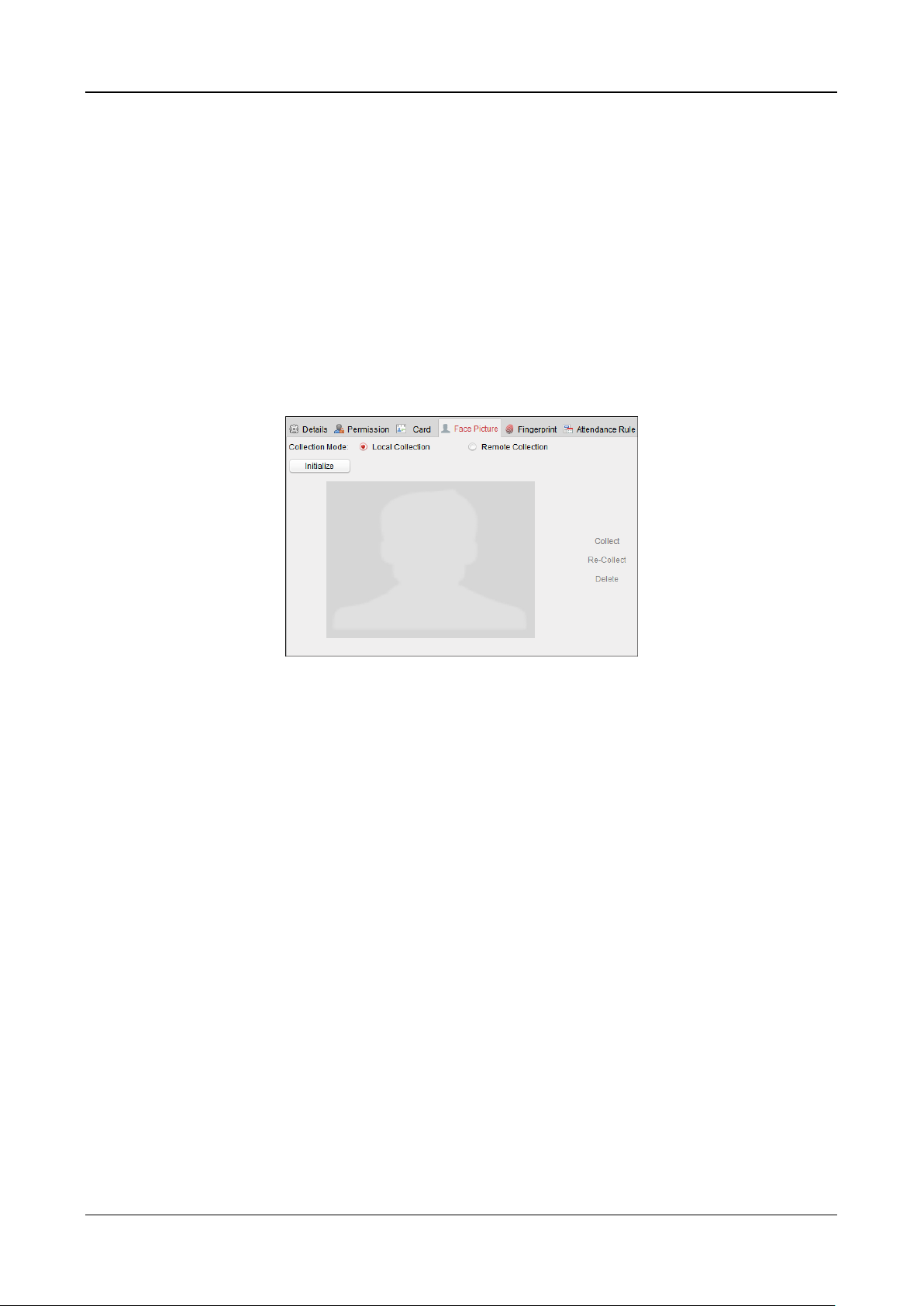
Swing Barrier·User Manual
73
13. (Optional) Click Link Face Picture to link the card with the face picture, so that the person can
pass the door by scanning the face via the device instead of swiping card when passing the
door.
14. Click OK to save the settings.
Adding Person (Face Picture)
You can collect the face picture in two ways: Local Collection and Remote Collection.
Local Collection: Collect the face picture via face picture scanner.
Remote Collection: Collect the face picture via the access control terminal.
Note: The access control terminal should support face recognition function.
Steps:
1. In the Add Person interface, click Face Picture tab
2. To get the face picture via face picture scanner:
1) Select Local Collection.
2) Connect the face picture scanner to the PC running the client.
3) Select the device type.
Note: Currently, the face picture scanner of DS2CS5432B-S is supported.
4) (Optional) You can click Initialize to initialize the face picture scanner.
3. To get the face picture via access control terminal:
1) Select Remote Collection.
2) Click Select Device to select the access control terminal which supports face recognition
function.
4. Click Collect to capture the face picture.
You can click Re-Collect the captured picture again.
You can click Delete to delete the captured picture.
5. Click OK to save the settings.
Adding Person (Fingerprint)
Steps:
1. In the Add Person interface, click Fingerprint tab.

Swing Barrier·User Manual
74
2. Select Local Collection as desired.
3. Before inputting the fingerprint, you should connect the fingerprint machine to the PC and set
its parameters first.
Click Set Fingerprint Machine to enter the following dialog box.
1) Select the device type.
Currently, the supported fingerprint machine types include DS-K1F800-F, DS-K1F810-F,
DS-K1F820-F, and DS-K1F181-F.
2) For fingerprint machine type DS-K1F800-F, you can set the serial port number, baud rate,
and overtime parameters of the fingerprint machine.
3) Click Save button to save the settings.
You can click Restore Default Value button to restore the default settings.
Notes:
The serial port number should correspond to the serial port number of PC. You can check
the serial port number in Device Manager in your PC.
The baud rate should be set according to the external fingerprint card reader. The default
value is 19200.
Timeout after field refers to the valid fingerprint collecting time. If the user does not input
a fingerprint or inputs a fingerprint unsuccessfully, the device will indicate that the
fingerprint collecting is over.
4. Click Start button, click to select the fingerprint to start collecting.
5. Lift and rest the corresponding fingerprint on the fingerprint scanner twice to collect the
fingerprint to the client.
6. (Optional) You can also click Remote Collection to collect fingerprint from the device.
Note: The function should be supported by the device.
7. (Optional) You can select the registered fingerprint and click Delete to delete it.

Swing Barrier·User Manual
75
You can click Clear to clear all fingerprints.
8. Click OK to save the fingerprints.
Adding Person (Attendance Rule)
You can set the attendance rule for the person.
Note: This tab page will display when you select Non-Residence mode in the application scene
when running the software for the first time.
Steps:
1. In the Add Person interface, click Attendance Rule tab.
2. If the person joins in the time and attendance, check the Time and Attendance checkbox to
enable this function for the person. Then the person’s card swiping records will be recorded
and analyzed for time and attendance.
For details about Time and Attendance, click More to go to the Time and Attendance module.
3. Click OK to save the settings.
Importing and Exporting Person Information
The person information can be imported and exported in batch.
Steps:
1. Exporting Person: You can export the added persons’ information in Excel format to the local
PC.
1) After adding the person, you can click Export Person button in the Person and Card tab to
pop up the following dialog.
2) Click to select the path of saving the exported Excel file.
3) Check the checkboxes to select the person information to export.

Swing Barrier·User Manual
76
4) Click OK to start exporting.
2. Importing Person: You can import the Excel file with persons information in batch from the
local PC
1) click Import Person button in the Person and Card tab.
2) You can click Download Template for Importing Person to download the template first.
3) Input the person information to the downloaded template.
4) Click to select the Excel file with person information.
5) Click OK to start importing.
Getting Person Information from Access Control Device
If the added access control device has been configured with person information (including person
details, fingerprint, issued card information), you can get the person information from the device
and import to the client for further operation.
Note: This function is only supported by the device the connection mothod of which is TCP/IP
when adding the device.
Steps:
1. In the organization list on the left, click to select an organization to import the persons.
2. Click Get Person button to pop up the following dialog box.

Swing Barrier·User Manual
77
3. The added access control device will be displayed.
4. Click to select the device and then click OK to start getting the person information from the
device.
You can also double click the device name to start getting the person information.
Notes:
The person information, including person details, person’s fingerprint information (if
configured), and the linked card (if configured), will be imported to the selected organization.
If the person name stored in the device is empty, the person name will be filled with the issued
card No. after importing to the client.
The gender of the persons will be Male by default.
Up to 10000 persons can be imported.
7.4.2 Managing Person
Modifying and Deleting Person
To modify the person information and attendance rule, click or in the Operation column,
or select the person and click Modify to open the editing person dialog.
You can click to view the person’s card swiping records.
To delete the person, select a person and click Delete to delete it.
Note: If a card is issued to the current person, the linkage will be invalid after the person is deleted.
Changing Person to Other Organization
You can move the person to another organization if needed.
Steps:
1. Select the person in the list and click Change Organization button.

Swing Barrier·User Manual
78
2. Select the organization to move the person to.
3. Click OK to save the settings.
Searching Person
You can input the keyword of card No. or person name in the search field, and click Search to
search the person.
You can input the card No. by clicking Read to get the card No. via the connected card enrollment
station.
You can click Set Card Enrollment Station in the dropdown list to set the parameters.
7.4.3 Issuing Card in Batch
You can issue multiple cards for the person with no card issued in batch.
Steps:
1. Click Issue Card in Batch button to enter the following dialog.
All the added person with no card issued will display in the Person(s) with No Card Issued list.
2. Select the card type according to actual needs.
Note: For details about the card type, refer to Adding Person.
3. Input the password of the card itself in the Card Password field. The card password should
contain 4 to 8 digits.
Note: The password will be required when the card holder swiping the card to get enter to or
exit from the door if you enable the card reader authentication mode as Card and Password,
Password and Fingerprint, and Card, Password, and Fingerprint. For details, refer to Chapter
7.6.2 Card Reader Authentication.
4. Input the card quantity issued for each person.
For example, if the Card Quantity is 3, you can read or enter three card No. for each person.

Swing Barrier·User Manual
79
5. Click to set the effective time and expiry time of the card.
6. In the Person(s) with No Card Issued list on the left, select the person to issue card.
Note: You can click on the Person Name, Gender, and Department column to sort the persons
according to actual needs.
7. Select the Card Reader Mode for reading the card No.
Access Controller Reader: Place the card on the reader of the Access Controller and click
Read to get the card No.
Card Enrollment Station: Place the card on the Card Enrollment Station and click Read to
get the card No.
Note: The Card Enrollment Station should connect with the PC running the client. You can
click Set Card Enrollment Station to enter the following dialog.
1) Select the Card Enrollment Station type.
Note: Currently, the supported card reader types include DS-K1F100-D8, DS-K1F100-M,
DS-K1F100-D8E, and DS-K1F180-D8E.
2) Set the parameters about the connected card enrollment station.
If the card is M1 card, and if you need to enable the M1 Card Encryption function, you
should check Enable checkbox of M1 Card Encryption and click Modify to select the
sector.
3) Click Save button to save the settings.
You can click Restore Default Value button to restore the defaults.
Manually Input: Input the card No. and click Enter to input the card No.
8. After issuing the card to the person, the person and card information will display in the
Person(s) with Card Issued list.
9. Click OK to save the settings.
7.5 Permission Configuration
In Permission Configuration module, you can add, edit, and delete the access control permission,
and then apply the permission settings to the device to take effect.
Click icon to enter the Access Control Permission interface.
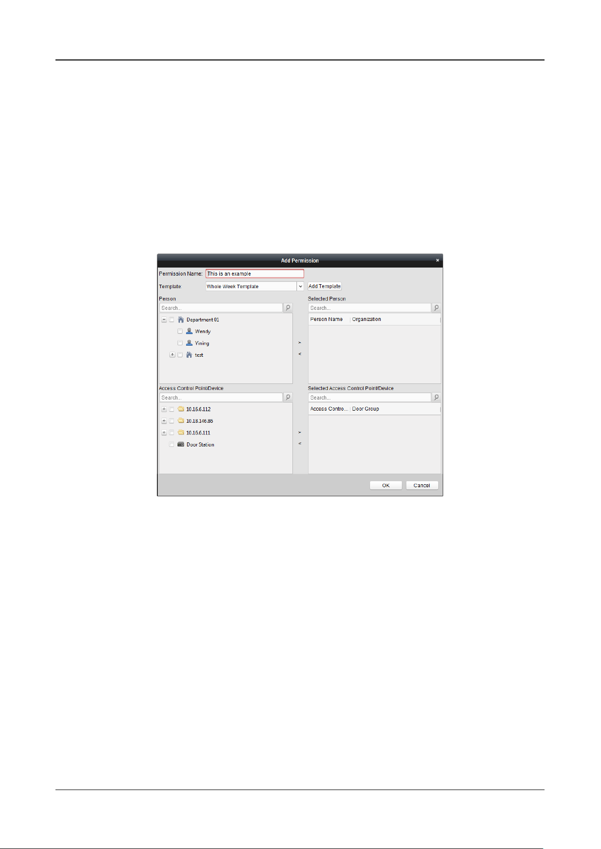
Swing Barrier·User Manual
80
7.5.1 Adding Permission
Purpose:
You can assign permission for persons to enter/exist the access control points (doors) in this
section.
Notes:
You can add up to 4 permissions to one access control point of one device.
You can add up to 128 permissions in total.
Steps:
1. Click Add icon to enter following interface.
2. In the Permission Name field, input the name for the permission as desired.
3. Click on the dropdown menu to select a template for the permission.
Note: You should configure the template before permission settings. You can click Add
Template button to add the template.
4. In the Person list, all the added persons display.
Check the checkbox(es) to select person(s) and click > to add to the Selected Person list.
(Optional) You can select the person in Selected Person list and click < to cancel the selection.
5. In the Access Control Point/Device list, all the added access control points (doors) and door
stations will display.
Check the checkbox(es) to select door(s) or door station(s) and click > to add to the selected
list.
(Optional) You can select the door or door station in the selected list and click < to cancel the
selection.
6. Click OK button to complete the permission adding. The selected person will have the
permission to enter/exit the selected door/door station with their linked card(s) or fingerprints.
7. (Optional) after adding the permission, you can click Details to modify it. Or you can select the
permission and click Modify to modify.

Swing Barrier·User Manual
81
You can select the added permission in the list and click Delete to delete it.
7.5.2 Applying Permission
Purpose:
After configuring the permissions, you should apply the added permission to the access control
device to take effect.
Steps:
1. Select the permission(s) to apply to the access control device.
To select multiple permissions, you can hold the Ctrl or Shift key and select permissions.
2. Click Apply All to start applying all the selected permission(s) to the access control device or
door station.
You can also click Apply Changes to apply the changed part of the selected permission(s) to the
device(s).
3. The following window will pop up, indicating the applying permission result.
Notes:
When the permission settings are changed, the following hint box will pop up.
You can click Apply Now to apply the changed permissions to the device.
Or you can click Apply Later to apply the changes later in the Permission interface.
The permission changes include changes of schedule and template, permission settings,
person’s permission settings, and related person settings (including card No., fingerprint, face
picture, linkage between card No. and fingerprint, linkage between card No. and fingerprint,
card password, card effective period, etc).
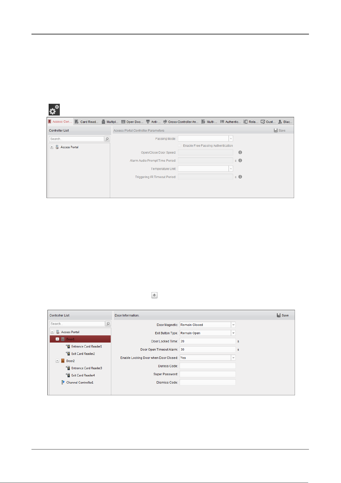
Swing Barrier·User Manual
82
7.6 Advanced Functions
Purpose:
After configuring the person, template, and access control permission, you can configure the
advanced functions of access control application, such as access control parameters,
authentication password, and opening door with first card, anti-passing back, etc.
Note: The advanced functions should be supported by the device.
Click icon to enter the following interface.
7.6.1 Access Control Parameters
Purpose:
After adding the access control device, you can configure its access control point (door)’s
parameters, and its card readers’ parameters.
Click Access Control Parameters tab to enter the parameters settings interface.
Door Parameters
Steps:
1. In the controller list on the left, click to expand the access control device, select the door
(access control point) and you can edit the information of the selected door on the right.
2. You can edit the following parameters:
Door Magnetic: The Door Magnetic is in the status of Remain Closed (excluding special
conditions).
Exit Button Type: The Exit Button Type is in the status of Remain Open (excluding special

Swing Barrier·User Manual
83
conditions).
Door Locked Time: After swiping the normal card and relay action, the timer for locking
the door starts working.
Door Open Timeout Alarm: The alarm can be triggered if the door has not been close
Enable Locking Door when Door Closed: The door can be locked once it is closed even if
the Door Locked Time is not reached.
Duress Code: The door can open by inputting the duress code when there is duress. At the
same time, the client can report the duress event.
Super Password: The specific person can open the door by inputting the super password.
Dismiss Code: Input the dismiss code to stop the buzzer of the card reader.
Notes:
The duress code, Super password, and dismiss code should be different.
The duress code, super password, and the dismiss code should be different from the
authentication password.
The duress code, super password, and the dismiss code should contain 4 to 8 numerics.
3. Click Save button to save parameters.
Card Reader Parameters
Steps:
1. In the device list on the left, click to expand the door, select the card reader name and you
can edit the card reader parameters on the right.
2. You can edit the following parameters:
Nickname: Edit the card reader name as desired.
Enable Card Reader: Select Yes to enable the card reader.
OK LED Polarity: Select the OK LED Polarity of the card reader mainboard.
Error LED Polarity: Select the Error LED Polarity of the card reader mainboard.

Swing Barrier·User Manual
84
Buzzer Polarity: Select the Buzzer LED Polarity of the card reader mainboard.
Minimum Card Swiping Interval: If the interval between card swiping of the same card is
less than the set value, the card swiping is invalid. You can set it as 0 to 255.
Max. Interval When Inputting Password: When you inputting the password on the card
reader, if the interval between pressing two digits is larger than the set value, the digits
you pressed before will be cleared automatically.
Enable Failed Attempts Limit of Card Reading: Enable to report alarm when the card
reading attempts reach the set value.
Max. Times of Card Swiping Failure: Set the max. failure attempts of reading card.
Enable Tampering Detection: Enable the anti-tamper detection for the card reader.
Detect When Card Reader is Offline for: When the access control device cannot connect
with the card reader for longer than the set time, the card reader will turn offline
automatically.
Buzzing Time: Set the card reader buzzing time. The available time ranges from 0 to 5999s.
0 represents continuous buzzing.
Card Reader Type: Get the card reader’s type.
Card Reader Description: Get the card reader description.
Fingerprint Recognition Level: Select the fingerprint recognition level in the dropdown list.
By default, the level is Low.
3. Click the Save button to save parameters.
Lane Controller Parameters
Steps:
1. In the device list on the left, click to expand the door, select a lane controller and you can
edit the lane controller’s parameters on the right.
2. You can edit the following parameters:
Passing Mode: Select the controller which will control the barrier status of the device.
If select According to Lane Controller’s DIP Settings, the device will follow the lane
controller’s DIP settings to control the barrier. The settings on the software system will be
invalid.
If select According to Main Controller’s Settings, the device will follow the settings of the

Swing Barrier·User Manual
85
software system to control the barrier. The DIP settings of the lane controller will be
invalid.
Note: For details about setting the barrier status, see 7.9.2 Anti-control the Access Control
Point (Door).
Enable Free Passing Authentication: If check the checkbox, when both entrance and exit’s
barrier mode is Remain Open, the pedestrians should authenticate each time passing
through the lane. Or an alarm will be triggered.
Open/Close Door Speed: Set the barrier’s open and close speed. You can select from 1 to
10. The greater the value, the faster the speed.
Note: The suggested value is 6.
Alarm Audio Prompt Time Duration: Set the alarm audio prompt playing duration.
Note: 0 refers to the alarm audio will be played until the alarm is ended.
Temperature Unit: Select the temperature unit that displayed in the device status.
Note: For details about viewing device status, see 7.2.2 Viewing Device Status.
Barrier Material: Select the material of the barrier gate. You can select the barrier
material from the drop-down list.
Note: This parameter affects the working of the barrier gate. Please correctly set the
material according to the actual situation so that the barrier can open and close properly.
Lane Length: The width of the lane. You can set the lane width.
Note: This parameter affects the working of the barrier gate. Please correctly set the
width according to the actual situation so that the barrier can open and close properly.
Do Not Open Barrier in Authenticates in Lane: If there is someone or something in the
lane, the gate will not open even if the credential is authenticated.
This function is designed to avoid more than one person passing through the gate with
only one authentication.
3. Click Save to save the lane controller’s parameters.
7.6.2 Card Reader Authentication
Purpose:
You can set the passing rules for the card reader of the access control device.
Steps:
1. Click Card Reader Authentication tab and select a card reader on the left.
2. Click Configuration button to select the card reader authentication modes for setting the
schedule.
Notes:
The available authentication modes depend on the device type.
Password refers to the card password set when issuing the card to the person in Chapter
7.4 Person Management.
1) Select the modes and click to add to the selected modes list.
You can click or to adjust the display order.

Swing Barrier·User Manual
86
2) Click OK to confirm the selection.
3. After selecting the modes, the selected modes will display as icons.
Click the icon to select a card reader authentication mode.
4. Click and drag your mouse on a day to draw a color bar on the schedule, which means in that
period of time, the card reader authentication is valid.
5. Repeat the above step to set other time periods.
Or you can select a configured day and click Copy to Week button to copy the same settings to
the whole week.
(Optional) You can click Delete button to delete the selected time period or click Clear button
to delete all the configured time periods.
6. (Optional) Click Copy to button to copy the settings to other card readers.

Swing Barrier·User Manual
87
7. Click Save button to save parameters.
7.6.3 Multiple Authentication
Purpose:
You can manage the cards by group and set the authentication for multiple cards for one access
control point (door).
Note: Please set the card permission and apply the permission setting to the access control device
first. For details, refer to Chapter 7.5 Permission Configuration.
Steps:
1. Click Multiple Authentication tab to enter the following interface.
2. Select access control device from the list on the left.
3. In the Set Card Group panel on the right, click Add button to pop up the following dialog:

Swing Barrier·User Manual
88
1) In the Card Group Name field, input the name for the group as desired.
2) Click to set the effective time and expiry time of the card group.
3) Check the checkbox(es) to select the card(s) to add the card group.
4) Click OK to save the card group.
4. In the Set Authentication Group panel, select the access control point (door) of the device for
multiple authentications.
5. Input the time interval for card swiping.
6. Click Add to pop up the following dialog.

Swing Barrier·User Manual
89
1) Select the template of the authentication group from the dropdown list.
2) Select the authentication type of the authentication group from the dropdown list.
Local Authentication: Authentication by the access control device.
Local Authentication and Remotely Open Door: Authentication by the access control
device and by the client.
For Local Authentication and Remotely Open Door type, you can check the checkbox
to enable the super password authentication when the access control device is
disconnected with the client.
Local Authentication and Super Password: Authentication by the access control
device and by the super password.
3) In the list on the left, the added card group will display. You can click the card group and
click to add the group to the authentication group.
You can click the added card group and click to remove it from the authentication
group.
You can also click or to set the card swiping order.
4) Input the Card Swiping Times for the selected card group.
Notes:
The Card Swiping Times should be larger than 0 and smaller than the added card
quantity in the card group.
The upper limit of Card Swiping Times is 16.
5) Click OK to save the settings.
7. Click Save to save and take effect of the new settings.
Notes:
For each access control point (door), up to 20 authentication groups can be added.

Swing Barrier·User Manual
90
For the authentication group which certificate type is Local Authentication, up to 8 card
groups can be added to the authentication group.
For the authentication group which certificate type is Local Authentication and Super
Password or Local Authentication and Remotely Open Door, up to 7 card groups can be
added to the authentication group.
7.6.4 Open Door with First Card
Purpose:
You can set multiple first cards for one access control point. After the first card swiping, it allows
multiple persons access the door or other authentication actions. The first card mode contains
Remain Open with First Card, Disable Remain Open with First Card, and First Card Authorization.
Remain Open with First Card: The door remains open for the configured time duration after
the first card swiping until the remain open duration ends.
Disable Remain Open with First Card: Disable the function.
First Card Authorization: All authentications (except for the authentications of super card,
super password, duress card, and duress code) are allowed only after the first card
authorization.
Notes:
The first card authorization is effective only on the current day. The authorization will be
expired after 24:00 on the current day.
You can swipe the first card again to disable the first card mode.
Steps:
1. Click Open Door with First Card tab to enter the following interface.
2. Select an access control device from the list on the left.
3. Select the first card mode in the drop-down list for the access control point.
4. (Optional) If you select Remain Open with First Card, you should set remain open duration.
Notes:
The Remain Open Duration should be between 0 and 1440 minutes. By default, it is 10
minutes.

Swing Barrier·User Manual
91
You can swipe the first card again to disable the first card mode.
5. In the First Card list, Click Add button to pop up the following dialog box.
1) Select the cards to add as first card for the door
Note: Please set the card permission and apply the permission setting to the access
control device first. For details, refer to Chapter 7.5 Permission Configuration.
2) Click OK button to save adding the card.
6. You can click Delete button to remove the card from the first card list.
7. Click Save to save and take effect of the new settings.
7.6.5 Anti-Passing Back
Purpose:
You can set to only pass the access control point according to the specified path and only one
person could pass the access control point after swiping the card.
Notes:
Either the anti-passing back or multi-door interlocking function can be configured for an access
control device at the same time.
You should enable the anti-passing back function on the access control device first.
Steps:
1. Click Anti-passing Back tab to enter the following interface.
 Loading...