


ITNC 530 - 6-2010 DIN-ISO PROGRAMMING
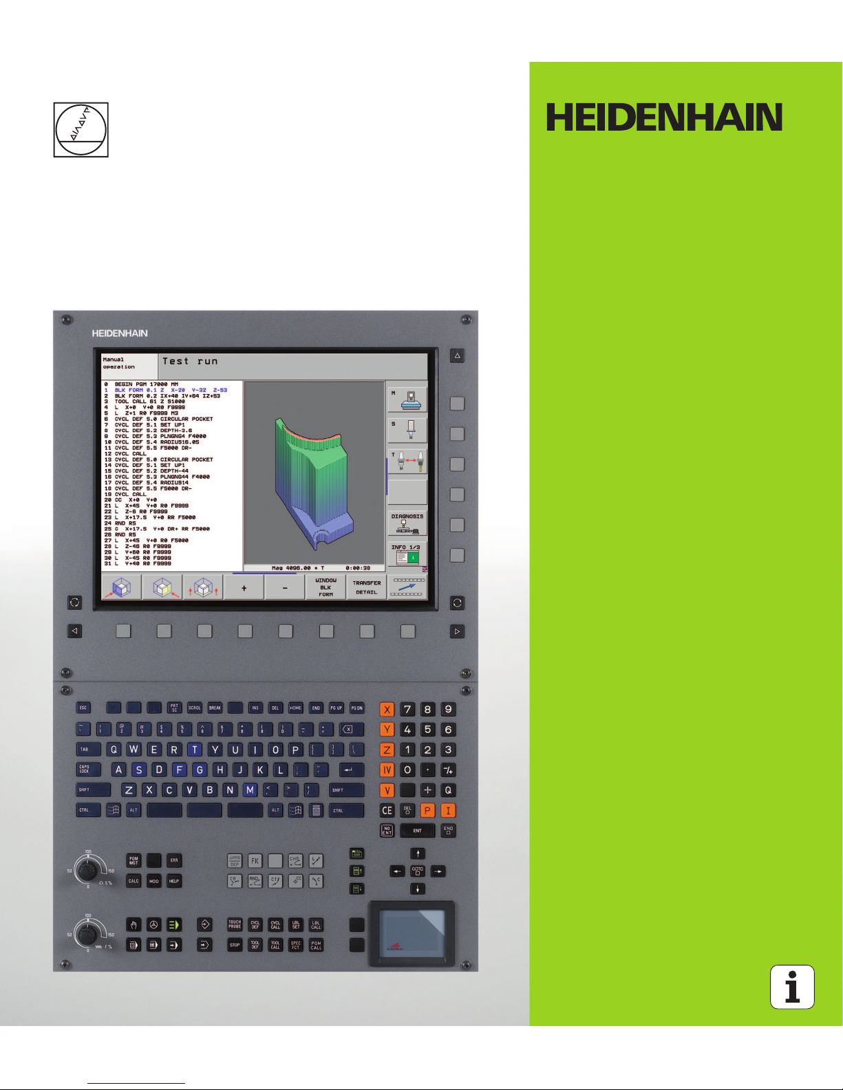
User’s Manual
DIN/ISO
Programming
iTNC 530
NC Software
606 420-01
606 421-01
English (en)
6/2010
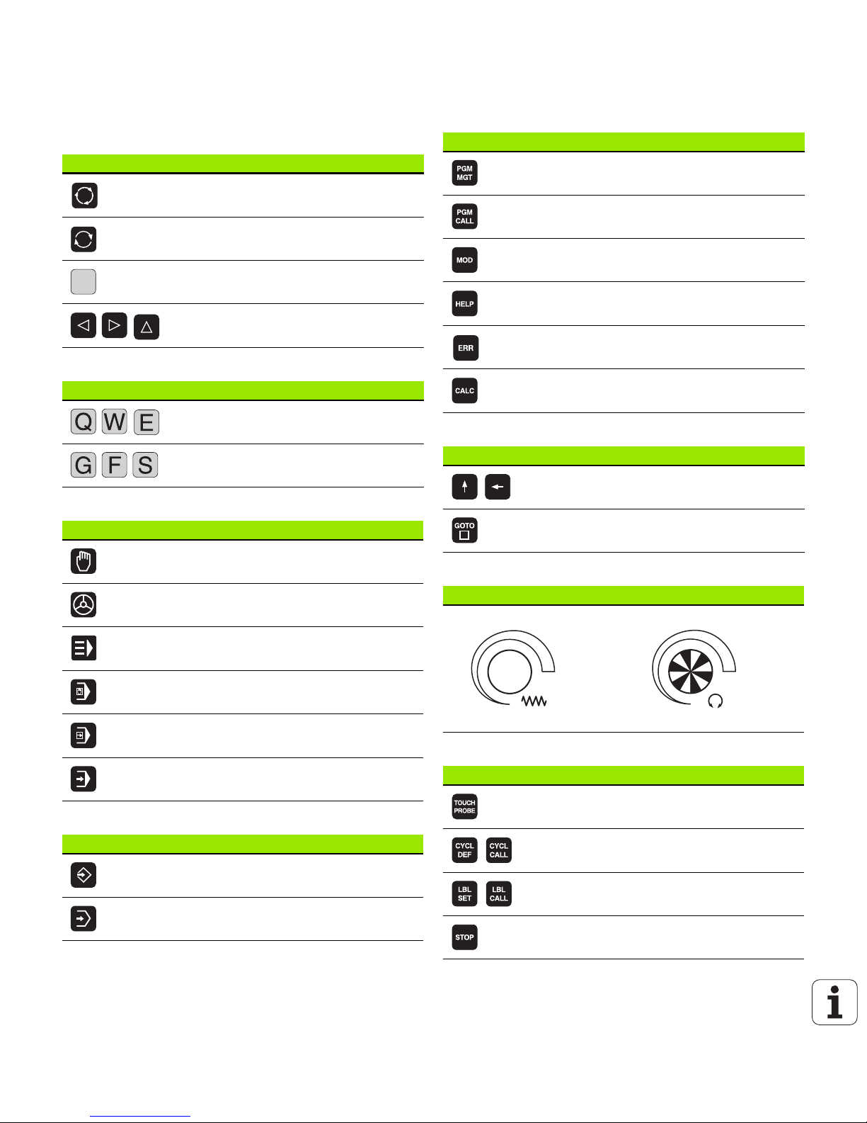
Controls of the TNC
Keys on visual display unit
Alphanumeric keyboard
Machine operating modes
Programming modes
Program/file management, TNC functions
Navigation keys
Potentiometer for feed rate and spindle speed
Cycles, subprograms and program section repeats
Key Function
Split screen layout
Toggle the display between machining
and programming modes
Soft keys for selecting functions on
screen
Shifts between soft-key rows
Key Function
File names, comments
DIN/ISO programming
Key Function
Manual Operation
Electronic Handwheel
smarT.NC
Positioning with Manual Data Input
Program Run, Single Block
Program Run, Full Sequence
Key Function
Programming and Editing
Test Run
Key Function
Select or delete programs and files,
external data transfer
Define program call, select datum and
point tables
Select MOD functions
Display help text for NC error messages,
call TNCguide
Display all current error messages
Show calculator
Key Function
Move highlight
Go directly to blocks, cycles and
parameter functions
Feed rate Spindle speed
Key Function
Define touch probe cycles
Define and call cycles
Enter and call labels for subprogramming
and program section repeats
Program stop in a program
1
50
0
50
100
F %
1
50
0
50
100
S %
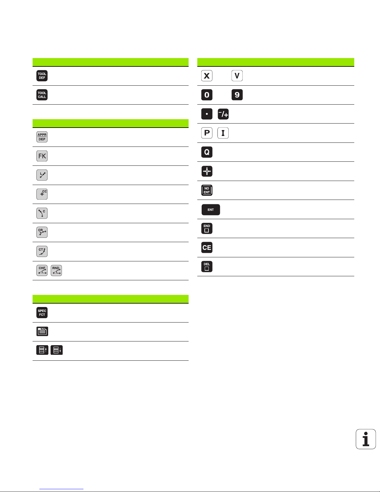
Tool functions
Programming path movements
Special functions / smarT.NC
Coordinate axes and numbers: Entering and editing
Key Function
Define tool data in the program
Call tool data
Key Function
Approach/depart contour
FK free contour programming
Straight line
Circle center/pole for polar coordinates
Circle with center
Circle with radius
Circular arc with tangential connection
Chamfering/corner rounding
Key Function
Show special functions
smarT.NC: Select next tab on form
smarT.NC: Select first input field in
previous/next frame
Key Function
Select coordinate axes or
enter them into the program
Numbers
Decimal point / Reverse algebraic sign
Polar coordinate input / Incremental
values
Q parameter programming /
Q parameter status
Save actual position or values from
calculator
Skip dialog questions, delete words
Confirm entry and resume dialog
Conclude block and exit entry
Clear numerical entry or TNC error
message
Abort dialog, delete program section


About this Manual
HEIDENHAIN iTNC 530 5
About this Manual
The symbols used in this manual are described below.
Would you like any changes, or have you found
any errors?
We are continuously striving to improve documentation for you.
Please help us by sending your requests to the following e-mail
address: tnc-userdoc@heidenhain.de.
This symbol indicates that important notes about the
function described must be adhered to.
This symbol indicates that there is one or more of the
following risks when using the described function:
Danger to workpiece
Danger to fixtures
Danger to tool
Danger to machine
Danger to operator
This symbol indicates that the described function must be
adapted by the machine tool builder. The function
described may therefore vary depending on the machine.
This symbol indicates that you can find detailed
information about a function in another manual.

TNC Model, Software and Features
6
TNC Model, Software and Features
This manual describes functions and features provided by TNCs as of
the following NC software numbers.
The suffix E indicates the export version of the TNC. The export
version of the TNC has the following limitations:
Simultaneous linear movement in up to 4 axes
HSCI (HEIDENHAIN Serial Controller Interface) identifies the new
hardware platform of the TNC controls.
HeROS 5 identifies the new operating system of HSCI-based TNC
controls.
The machine tool builder adapts the usable features of the TNC to his
machine by setting machine parameters. Some of the functions
described in this manual may therefore not be among the features
provided by the TNC on your machine tool.
TNC functions that may not be available on your machine include:
Tool measurement with the TT
Please contact your machine tool builder to become familiar with the
features of your machine.
TNC model NC software number
iTNC 530, HSCI and HeROS 5 606 420-01
iTNC 530, HSCI and HeROS 5 606 421-01

TNC Model, Software and Features
HEIDENHAIN iTNC 530 7
Many machine manufacturers, as well as HEIDENHAIN, offer
programming courses for the TNCs. We recommend these courses as
an effective way of improving your programming skill and sharing
information and ideas with other TNC users.
User’s Manual for Cycle Programming:
All of the cycle functions (touch probe cycles and fixed
cycles) are described in a separate manual. Please contact
HEIDENHAIN if you require a copy of this User’s Manual.
ID: 670 388-xx
smarT.NC user documentation:
The smarT.NC operating mode is described in a separate
Pilot. Please contact HEIDENHAIN if you require a copy of
this Pilot. ID: 533 191-xx.

TNC Model, Software and Features
8
Software options
The iTNC 530 features various software options that can be enabled
by you or your machine tool builder. Each option is to be enabled
separately and contains the following respective functions:
Software option 1
Cylinder surface interpolation (Cycles 27, 28, 29 and 39)
Feed rate in mm/min for rotary axes: M116
Tilting the machining plane (Cycle 19, PLANE function and 3-D ROT
soft key in the Manual operating mode)
Circle in 3 axes with tilted working plane
Software option 2
Block processing time 0.5 ms instead of 3.6 ms
5-axis interpolation
Spline interpolation
3-D machining:
M114: Automatic compensation of machine geometry when
working with swivel axes
M128: Maintaining the position of the tool tip when positioning
with tilted axes (TCPM)
FUNCTION TCPM: Maintaining the position of the tool tip when
positioning with tilted axes (TCPM) in selectable modes
M144: Compensating the machine’s kinematic configuration for
ACTUAL/NOMINAL positions at end of block
Additional parameters for finishing/roughing and tolerance
for rotary axes in Cycle 32 (G62)
LN blocks (3-D compensation)
DCM Collision software option Description
Function that monitors areas defined by the
machine manufacturer to prevent collisions.
Page 329
DXF Converter software option Description
Extract contours and machining positions
from DXF files (R12 format).
Page 218
Additional dialog language software
option
Description
Function for enabling the conversational
languages Slovenian, Slovak, Norwegian,
Latvian, Estonian, Korean, Turkish, Romanian,
Lithuanian.
Page 576

TNC Model, Software and Features
HEIDENHAIN iTNC 530 9
Global Program Settings software option Description
Function for superimposing coordinate
transformations in the Program Run modes,
handwheel superimposed traverse in virtual
axis direction.
Page 347
AFC software option Description
Function for adaptive feed-rate control for
optimizing the machining conditions during
series production.
Page 358
KinematicsOpt software option Description
Touch-probe cycles for inspecting and
optimizing the machine accuracy.
User’s Manual for
Cycles
3D-ToolComp software option Description
3-D radius compensation depending on the
tool’s contact angle for LN blocks.
Page 358

TNC Model, Software and Features
10
Feature content level (upgrade functions)
Along with software options, significant further improvements of the
TNC software are managed via the Feature Content Level (FCL)
upgrade functions. Functions subject to the FCL are not available
simply by updating the software on your TNC.
Upgrade functions are identified in the manual with FCL n, where n
indicates the sequential number of the feature content level.
You can purchase a code number in order to permanently enable the
FCL functions. For more information, contact your machine tool
builder or HEIDENHAIN.
All upgrade functions are available to you without surcharge
when you receive a new machine.
FCL 4 functions Description
Graphical depiction of the protected
space when DCM collision monitoring is
active
Page 333
Handwheel superimposition in stopped
condition when DCM collision
monitoring is active
Page 332
3-D basic rotation (set-up
compensation)
Machine Manual
FCL 3 functions Description
Touch probe cycle for 3-D probing User’s Manual for
Cycles
Touch probe cycles for automatic datum
setting using the center of a slot/ridge
User’s Manual for
Cycles
Feed-rate reduction for the machining of
contour pockets with the tool being in
full contact with the workpiece
User’s Manual for
Cycles
PLANE function: Entry of axis angle Page 398
User documentation as a
context-sensitive help system
Page 146
smarT.NC: Programming of smarT.NC
and machining can be carried out
simultaneously
Page 108
smarT.NC: Contour pocket on point
pattern
smarT.NC Pilot

TNC Model, Software and Features
HEIDENHAIN iTNC 530 11
Intended place of operation
The TNC complies with the limits for a Class A device in accordance
with the specifications in EN 55022, and is intended for use primarily
in industrially-zoned areas.
Legal information
This product uses open source software. Further information is
available on the control under
U Programming and Editing operating mode
U MOD function
U LEGAL INFORMATION soft key
smarT.NC: Preview of contour
programs in the file manager
smarT.NC Pilot
smarT.NC: Positioning strategy for
machining point patterns
smarT.NC Pilot
FCL 2 functions Description
3-D line graphics Page 138
Virtual tool axis Page 498
USB support of block devices (memory
sticks, hard disks, CD-ROM drives)
Page 118
Possibility of assigning different depths
to each subcontour in the contour
formula
User’s Manual for
Cycles
Touch-probe cycle for global setting of
touch-probe parameters
User’s Manual for
Touch Probe Cycles
smarT.NC: Graphic support of block
scan
smarT.NC Pilot
smarT.NC: Coordinate transformation smarT.NC Pilot
smarT.NC: PLANE function smarT.NC Pilot
FCL 3 functions Description

New functions 606 42x-01 since the predecessor versions 340 49x-05
12
New functions 606 42x-01 since the
predecessor versions 340 49x-05
Opening and Editing of externally created files is new (see
“Additional tools for management of external file types” on page
121)
New functions in the task bar added (see “Soft-key row” on page
80)
Enhanced functions for configuration of the Ethernet interface (see
“Configuring the TNC” on page 547)
Improvements regarding Functional Safety FS (option):
General information on Functional Safety FS (see “General
Information” on page 456)
Explanation of terms (see “Explanation of terms” on page 457)
Checking the axis positions (see “Check axis positions” on page
458)
Activating feed-rate limitation (see “Activating feed-rate
limitation” on page 460)
Improvements regarding the general status views of a TNC with
functional safety (see “Additional Status displays” on page 460)
The new HR 510, HR 520 and HR 550 FS handwheels are supported
(see “Traversing with electronic handwheels” on page 444)
New software option 3-D ToolComp: 3-D tool radius compensation
depending on the tool’s contact angle on blocks with surface normal
vectors (LN blocks)
3-D line graphics is now also possible in full-screen mode (see “3-D
Line Graphics (FCL2 Function)” on page 138)
A file selection dialog for selecting files in different NC functions and
in the table view of the pallet table is available now (see “Calling any
program as a subprogram” on page 240)
DCM: Saving and restoring of fixture situations
DCM: The form for test program generation now also contains icons
and tooltips (see “Check the position of the measured fixture” on
page 340)
DCM, FixtureWizard: Touch points and probing sequence are shown
more clearly now
DCM, FixtureWizard: Designations, touch points and measuring
points can be shown or hidden as desired.(see “Operating
FixtureWizard” on page 337)
DCM, FixtureWizard: Chucking equipment and insertion points can
now also be selected by mouse click
DCM: A library with standard chucking equipment is available now
(see “Fixture templates” on page 336)
DCM: Tool carrier management (see “Tool Holder Management
(DCM Software Option)” on page 344)

New functions 606 42x-01 since the predecessor versions 340 49x-05
HEIDENHAIN iTNC 530 13
In the Test Run mode, the working plane can now by defined
manually (see “Setting a tilted working plane for the test run” on
page 522)
On machines without encoders in the rotary axes, the rotary axis
coordinates to define the virtual axis direction VT can now be
specified via M114 (see “Virtual axis VT” on page 357)
In Manual mode the RW-3D mode for position display is now also
available (see “Position Display Types” on page 558)
Entries in the tool table TOOL.T (see “Tool table: Standard tool data”
on page 158)
New DR2TABLE column for definition of a compensation table for
tool radius compensation depending on the tool’s contact angle
New LAST_USE column, into which the TNC enters the date and
time of the last tool call
Q parameter programming: QS string parameters can now also be
used for jump addresses of conditional jumps, subprograms or
program section repeats (see "Calling a subprogram", page 238, see
"Calling a program section repeat", page 239 and see "Programming
If-Then decisions", page 264)
The generation of tool usage lists in the Program Run modes can be
configured in a form (see “Settings for the tool usage test” on page
175)
The behavior during deletion of tools from the tool table can now be
influenced via machine parameter 7263
(see “Editing tool
tables” on page 164)
In the positioning mode TURN of the PLANE function you can now
define a clearance height to which the tool is to be retracted before
tilting to tool axis direction (see “Automatic positioning:
MOVE/TURN/STAY (entry is mandatory)” on page 400)
The following additional functions are now available in the expanded
tool management (see “Tool management (software option)” on
page 178):
Columns with special functions are also editable now
The form view of the tool data can now be exited with or without
saving changed values
The table view now offers a search function
Indexed tools are now shown correctly in the form view
The tool sequence list includes more detailed information now
The loading and unloading list of the tool magazine can now be
loaded and unloaded by drag and drop
Columns in the table view can be moved simply by drag and drop
Several special functions (SPEC FCT) are now available in the MDI
operating mode (see “Programming and Executing Simple
Machining Operations” on page 500)
There is a new manual probing cycle that can be used to
compensate workpiece misalignments by rotating the rotary table
(see “Workpiece alignment using 2 points” on page 483)

New functions 606 42x-01 since the predecessor versions 340 49x-05
14
New touch probe cycle for calibrating a touch probe by means of a
calibration sphere (see User's Manual for Cycle Programming)
KinematicsOpt: Better support for positioning of Hirth-coupled axes
(see User's Manual for Cycle Programming)
KinematicsOpt: An additional parameter for determination of the
backlash in a rotary axis was introduced (see User's Manual for
Cycle Programming)
New Cycle 275 for Trochoidal Slot Milling (see User’s Manual for
Cycle Programming)
In Cycle 241 "Single-Fluted Deep-Hole Drilling" it is now possible to
define a dwell depth (see User's Manual for Cycle Programming)
The approach and departure behavior of Cycle 39 "Cylinder Surface
Contour" can now be adjusted (see User's Manual for Cycle
Programming)

Changed functions 606 42x-01 since the predecessor versions 340 49x-06
HEIDENHAIN iTNC 530 15
Changed functions 606 42x-01 since
the predecessor versions 340 49x-06
In the calibration menus for touch probe length and radius, the
number and name of the active tool are also displayed now (if the
calibration data from the tool table are to be used, MP7411 = 1, see
"Managing more than one block of calibrating data", page 477).
During tilting in the Distance-To-Go mode, the PLANE function now
shows the angle actually left to be traversed until the target position
(see “Position display” on page 385).
The approach behavior during side finishing with Cycle 24 (DIN/ISO:
G124) was changed (see User's Manual for Cycle Programming).

Changed functions 606 42x-01 since the predecessor versions 340 49x-06
16

HEIDENHAIN iTNC 530 17
Table of Contents
First Steps with the iTNC 530
1
Introduction
2
Programming: Fundamentals, File
Management
3
Programming: Programming Aids
4
Programming: Tools
5
Programming: Programming Contours
6
Programming: Miscellaneous Functions
7
Programming: Data Transfer from DXF
Files
8
Programming: Subprograms and Program
Section Repeats
9
Programming: Q Parameters
10
Programming: Miscellaneous Functions
11
Programming: Special Functions
12
Programming: Multiple Axis Machining
13
Programming: Pallet Editor
14
Positioning with Manual Data Input
15
Test Run and Program Run
16
MOD Functions
17
Tables and Overviews
18


HEIDENHAIN iTNC 530 19
1.1 Overview ..... 42
1.2 Machine Switch-On ..... 43
Acknowledge the power interruption and move to the reference points ..... 43
1.3 Programming the First Part ..... 44
Select the correct operating mode ..... 44
The most important TNC keys ..... 44
Create a new program/file management ..... 45
Define a workpiece blank ..... 46
Program layout ..... 47
Program a simple contour ..... 48
Create a cycle program ..... 50
1.4 Graphically Testing the Program ..... 52
Select the correct operating mode ..... 52
Select the tool table for the test run ..... 52
Choose the program you want to test ..... 53
Select the screen layout and the view ..... 53
Start the program test ..... 54
1.5 Tool Setup ..... 55
Select the correct operating mode ..... 55
Prepare and measure tools ..... 55
The tool table TOOL.T ..... 55
The pocket table TOOL_P.TCH ..... 56
1.6 Workpiece Setup ..... 57
Select the correct operating mode ..... 57
Clamp the workpiece ..... 57
Align the workpiece with a 3-D touch probe system ..... 58
Set the datum with a 3-D touch probe ..... 59
1.7 Running the First Program ..... 60
Select the correct operating mode ..... 60
Choose the program you want to run ..... 60
Start the program ..... 60
1 First Steps with the iTNC 530 ..... 41

20
2.1 The iTNC 530 ..... 62
Programming: HEIDENHAIN conversational, smarT.NC and ISO formats ..... 62
Compatibility ..... 62
2.2 Visual Display Unit and Keyboard ..... 63
Visual display unit ..... 63
Sets the screen layout ..... 64
Operating panel ..... 65
2.3 Operating Modes ..... 66
Manual Operation and Electronic Handwheel ..... 66
Positioning with Manual Data Input ..... 66
Programming and Editing ..... 67
Test Run ..... 67
Program Run, Full Sequence and Program Run, Single Block ..... 68
2.4 Status Displays ..... 69
“General” status display ..... 69
Additional status displays ..... 71
2.5 Window Manager ..... 79
Soft-key row ..... 80
2.6 Accessories: HEIDENHAIN 3-D Touch Probes and Electronic Handwheels ..... 81
3-D touch probes ..... 81
HR electronic handwheels ..... 82
2 Introduction ..... 61

HEIDENHAIN iTNC 530 21
3.1 Fundamentals ..... 84
Position encoders and reference marks ..... 84
Reference system ..... 84
Reference system on milling machines ..... 85
Polar coordinates ..... 86
Absolute and incremental workpiece positions ..... 87
Setting the datum ..... 88
3.2 Creating and Writing Programs ..... 89
Organization of an NC program in DIN/ISO ..... 89
Define the blank: G30/G31 ..... 89
Creating a new part program ..... 90
Programming tool movements in DIN/ISO format ..... 92
Actual position capture ..... 93
Editing a program ..... 94
The TNC search function ..... 98
3.3 File Management: Fundamentals ..... 100
Files ..... 100
Show externally created files on the TNC ..... 102
Data backup ..... 102
3.4 Working with the File Manager ..... 103
Directories ..... 103
Paths ..... 103
Overview: Functions of the file manager ..... 104
Calling the file manager ..... 105
Selecting drives, directories and files ..... 106
Creating a new directory (only possible on the drive TNC:\) ..... 109
Creating a new file (only possible on the drive TNC:\) ..... 109
Copying a single file ..... 110
Copying files into another directory ..... 111
Copying a table ..... 112
Copying a directory ..... 113
Choosing one of the last files selected ..... 113
Deleting a file ..... 114
Deleting a directory ..... 114
Marking files ..... 115
Renaming a file ..... 117
Additional functions ..... 118
Working with shortcuts ..... 120
Additional tools for management of external file types ..... 121
Data transfer to or from an external data medium ..... 125
The TNC in a network ..... 127
USB devices on the TNC (FCL 2 function) ..... 128
3 Programming: Fundamentals, File Management ..... 83

22
4.1 Adding Comments ..... 132
Function ..... 132
Entering comments during programming ..... 132
Inserting comments after program entry ..... 132
Entering a comment in a separate block ..... 132
Functions for editing of the comment ..... 133
4.2 Structuring Programs ..... 134
Definition and applications ..... 134
Displaying the program structure window / Changing the active window ..... 134
Inserting a structuring block in the (left) program window. ..... 134
Selecting blocks in the program structure window ..... 134
4.3 Integrated Pocket Calculator ..... 135
Operation ..... 135
4.4 Programming Graphics ..... 136
Generating / not generating graphics during programming ..... 136
Generating a graphic for an existing program. ..... 136
Block number display ON/OFF ..... 137
Erasing the graphic ..... 137
Magnifying or reducing a detail ..... 137
4.5 3-D Line Graphics (FCL2 Function) ..... 138
Function ..... 138
Functions of the 3-D line graphics ..... 138
Highlighting NC blocks in the graphics ..... 140
Block number display ON/OFF ..... 140
Erasing the graphic ..... 140
4.6 Immediate Help for NC Error Messages ..... 141
Displaying error messages ..... 141
Display HELP ..... 141
4.7 List of All Current Error Messages ..... 142
Function ..... 142
Show error list ..... 142
Window contents ..... 143
Calling the TNCguide help system ..... 144
Generating service files ..... 145
4.8 The Context-Sensitive Help System TNCguide (FCL3 Function) ..... 146
Function ..... 146
Working with the TNCguide ..... 147
Downloading current help files ..... 151
4 Programming: Programming Aids ..... 131

HEIDENHAIN iTNC 530 23
5.1 Entering Tool-Related Data ..... 154
Feed rate F ..... 154
Spindle speed S ..... 155
5.2 Tool Data ..... 156
Requirements for tool compensation ..... 156
Tool numbers and tool names ..... 156
Tool length L ..... 156
Tool radius R ..... 156
Delta values for lengths and radii ..... 157
Entering tool data into the program ..... 157
Entering tool data in the table ..... 158
Tool-carrier kinematics ..... 166
Using an external PC to overwrite individual tool data ..... 167
Pocket table for tool changer ..... 168
Calling tool data ..... 171
Tool change ..... 173
Tool usage test ..... 175
Tool management (software option) ..... 178
5.3 Tool Compensation ..... 182
Introduction ..... 182
Tool length compensation ..... 182
Tool radius compensation ..... 183
5 Programming: Tools ..... 153

24
6.1 Tool Movements ..... 188
Path functions ..... 188
Miscellaneous functions M ..... 188
Subprograms and program section repeats ..... 188
Programming with Q parameters ..... 188
6.2 Fundamentals of Path Functions ..... 189
Programming tool movements for workpiece machining ..... 189
6.3 Contour Approach and Departure ..... 192
Starting point and end point ..... 192
Tangential approach and departure ..... 194
6.4 Path Contours—Cartesian Coordinates ..... 196
Overview of path functions ..... 196
Straight line at rapid traverse G00
Straight line with feed rate G01 F ..... 197
Inserting a chamfer between two straight lines ..... 198
Corner rounding G25 ..... 199
Circle center I, J ..... 200
Circular path C around circle center CC ..... 201
Circular path G02/G03/G05 with defined radius ..... 202
Circular path G06 with tangential connection ..... 204
6.5 Path Contours—Polar Coordinates ..... 209
Overview ..... 209
Zero point for polar coordinates: pole I, J ..... 210
Straight line at rapid traverse G10
Straight line with feed rate G11 F ..... 210
Circular path G12/G13/G15 around pole I, J ..... 211
Circular path G16 with tangential connection ..... 212
Helical interpolation ..... 213
6 Programming: Programming Contours ..... 187

HEIDENHAIN iTNC 530 25
7.1 Processing DXF Files (Software Option) ..... 218
Function ..... 218
Opening a DXF file ..... 219
Basic settings ..... 220
Layer settings ..... 222
Specifying the reference point ..... 223
Selecting and saving a contour ..... 225
Selecting and storing machining positions ..... 228
Zoom function ..... 234
7 Programming: Data Transfer from DXF Files ..... 217

26
8.1 Labeling Subprograms and Program Section Repeats ..... 236
Labels ..... 236
8.2 Subprograms ..... 237
Operating sequence ..... 237
Programming notes ..... 237
Programming a subprogram ..... 237
Calling a subprogram ..... 238
8.3 Program Section Repeats ..... 239
Label G98 ..... 239
Operating sequence ..... 239
Programming notes ..... 239
Programming a program section repeat ..... 239
Calling a program section repeat ..... 239
8.4 Separate Program as Subprogram ..... 240
Operating sequence ..... 240
Programming notes ..... 240
Calling any program as a subprogram ..... 240
8.5 Nesting ..... 242
Types of nesting ..... 242
Nesting depth ..... 242
Subprogram within a subprogram ..... 243
Repeating program section repeats ..... 244
Repeating a subprogram ..... 245
8.6 Programming Examples ..... 246
8 Programming: Subprograms and Program Section Repeats ..... 235

HEIDENHAIN iTNC 530 27
9.1 Principle and Overview ..... 254
Programming notes ..... 256
Calling Q-parameter functions ..... 257
9.2 Part Families—Q Parameters in Place of Numerical Values ..... 258
Function ..... 258
9.3 Describing Contours through Mathematical Operations ..... 259
Function ..... 259
Overview ..... 259
Programming fundamental operations ..... 260
9.4 Trigonometric Functions ..... 261
Definitions ..... 261
Programming trigonometric functions ..... 262
9.5 If-Then Decisions with Q Parameters ..... 263
Function ..... 263
Unconditional jumps ..... 263
Programming If-Then decisions ..... 264
9.6 Checking and Changing Q Parameters ..... 265
Procedure ..... 265
9.7 Additional Functions ..... 266
Overview ..... 266
D14: ERROR: Displaying error messages ..... 267
D15 PRINT: Output of texts or Q parameter values ..... 271
D19 PLC: Transfer values to the PLC ..... 272
9.8 Entering Formulas Directly ..... 273
Entering formulas ..... 273
Rules for formulas ..... 275
Programming example ..... 276
9.9 String Parameters ..... 277
String processing functions ..... 277
Assigning string parameters ..... 278
Chain-linking string parameters ..... 279
Converting a numerical value to a string parameter ..... 280
Copying a substring from a string parameter ..... 281
Copying system data to a string parameter ..... 282
Converting a string parameter to a numerical value ..... 284
Checking a string parameter ..... 285
Finding the length of a string parameter ..... 286
Comparing alphabetic priority ..... 287
9 Programming: Q Parameters ..... 253

28
9.10 Preassigned Q Parameters ..... 288
Values from the PLC: Q100 to Q107 ..... 288
WMAT block: QS100 ..... 288
Active tool radius: Q108 ..... 288
Tool axis: Q109 ..... 289
Spindle status: Q110 ..... 289
Coolant on/off: Q111 ..... 289
Overlap factor: Q112 ..... 289
Unit of measurement for dimensions in the program: Q113 ..... 290
Tool length: Q114 ..... 290
Coordinates after probing during program run ..... 290
Deviation between actual value and nominal value during automatic tool measurement with the TT 130 ..... 291
Tilting the working plane with mathematical angles: rotary axis coordinates calculated by the TNC ..... 291
Measurement results from touch probe cycles (see also User’s Manual for Touch Probe Cycles) ..... 292
9.11 Programming Examples ..... 294

HEIDENHAIN iTNC 530 29
10.1 Entering Miscellaneous Functions M and STOP ..... 302
Fundamentals ..... 302
10.2 Miscellaneous Functions for Program Run Control, Spindle and Coolant ..... 303
Overview ..... 303
10.3 Miscellaneous Functions for Coordinate Data ..... 304
Programming machine-referenced coordinates: M91/M92 ..... 304
Activating the most recently entered datum: M104 ..... 306
Moving to positions in a non-tilted coordinate system with a tilted working plane: M130 ..... 306
10.4 Miscellaneous Functions for Contouring Behavior ..... 307
Smoothing corners: M90 ..... 307
Insert rounding arc between straight lines: M112 ..... 307
Do not include points when executing non-compensated line blocks: M124 ..... 308
Machining small contour steps: M97 ..... 309
Machining open contours corners: M98 ..... 311
Feed rate factor for plunging movements: M103 ..... 312
Feed rate in millimeters per spindle revolution: M136 ..... 313
Feed rate for circular arcs: M109/M110/M111 ..... 314
Calculating the radius-compensated path in advance (LOOK AHEAD): M120 ..... 315
Superimposing handwheel positioning during program run: M118 ..... 317
Retraction from the contour in the tool-axis direction: M140 ..... 318
Suppressing touch probe monitoring: M141 ..... 319
Delete modal program information: M142 ..... 320
Delete basic rotation: M143 ..... 320
Automatically retract tool from the contour at an NC stop: M148 ..... 321
Suppress limit switch message: M150 ..... 322
10.5 Miscellaneous Functions for Laser Cutting Machines ..... 323
Principle ..... 323
Output the programmed voltage directly: M200 ..... 323
Output voltage as a function of distance: M201 ..... 323
Output voltage as a function of speed: M202 ..... 324
Output voltage as a function of time (time-dependent ramp): M203 ..... 324
Output voltage as a function of time (time-dependent pulse): M204 ..... 324
10 Programming: Miscellaneous Functions ..... 301

30
11.1 Overview of Special Functions ..... 326
Main menu for SPEC FCT special functions ..... 326
Program defaults menu ..... 327
Functions for contour and point machining menu ..... 327
Menu of various DIN/ISO functions ..... 328
11.2 Dynamic Collision Monitoring (Software Option) ..... 329
Function ..... 329
Collision monitoring in the manual operating modes ..... 331
Collision monitoring in Automatic operation ..... 332
Graphic depiction of the protected space (FCL4 function) ..... 333
Collision monitoring in the Test Run mode of operation ..... 334
11.3 Fixture Monitoring (Software Option) ..... 335
Fundamentals ..... 335
Fixture templates ..... 336
Setting parameter values for the fixture: FixtureWizard ..... 336
Placing the fixture on the machine ..... 338
Editing fixtures ..... 339
Removing fixtures ..... 339
Check the position of the measured fixture ..... 340
Manage fixtures ..... 342
11.4 Tool Holder Management (DCM Software Option) ..... 344
Fundamentals ..... 344
Tool-holder templates ..... 344
Set the tool holder parameters: ToolHolderWizard ..... 345
Removing a tool holder ..... 346
11.5 Global Program Settings (Software Option) ..... 347
Function ..... 347
Technical prerequisites ..... 349
Activating/deactivating a function ..... 350
Basic rotation ..... 352
Swapping axes ..... 353
Superimposed mirroring ..... 354
Additional, additive datum shift ..... 354
Axis locking ..... 355
Superimposed rotation ..... 355
Feed rate override ..... 355
Handwheel superimposition ..... 356
11 Programming: Special Functions ..... 325
 Loading...