


 Loading...
Operation - Parts - Repair
Protective Coating |
|
|
Hand-Held Paint Sprayer |
3A2308C |
|
|
|
EN |
|
|
|
-For portable spray applications of protective coatings -
-For professional use only -
-Not approved for use in explosive atmospheres or hazardous locations -
-DO NOT SPRAY ZINC COATINGS OR MATERIALS WITH AGGREGATE.
ACCELERATED PUMP WEAR WILL OCCUR -
4000 psi (27.6 MPa, 276 bar) Maximum Working Pressure
IMPORTANT SAFETY INSTRUCTIONS
 Read all warnings and instructions in this manual. Save these instructions.
Model |
|
|
|
|
|
|
|
|
|
|
|
|
|
|
|
|
|
|
|
|
|
|
|
|
|
|
|
|
|
|
|
|
|
|
|
16H960 |
|
|
|
|
|
|
|
|
|
|
|
16N654 |
|
|
|
|
|
|
|
|
|
|
|
16N927 |
|
|
|
|
|
|
|
|
|
|
|
16N655 |
|
|
|
|
|
|
|
|
|
|
|
16N656 |
|
|
|
|
|
|
|
|
|
|
|
ti19340a

Table of Contents
Warnings . . . . . . . . . . . . . . . . . . . . . . . . . . . . . . . . . . . . . . 3 Component Identification . . . . . . . . . . . . . . . . . . . . . . . . . 6 Operation . . . . . . . . . . . . . . . . . . . . . . . . . . . . . . . . . . . . . . 7
Charging the Battery . . . . . . . . . . . . . . . . . . . . . . . . . . 7 Charger Status Indicator Lights . . . . . . . . . . . . . . . . . . 7 Sprayer Status Indicator . . . . . . . . . . . . . . . . . . . . . . . . 8 Common Procedures . . . . . . . . . . . . . . . . . . . . . . . . . . 9 Adjusting Pressure . . . . . . . . . . . . . . . . . . . . . . . . . . . 10 Setup . . . . . . . . . . . . . . . . . . . . . . . . . . . . . . . . . . . . . 12 Starting a New Job . . . . . . . . . . . . . . . . . . . . . . . . . . . 12 Install/Service Filter (if needed) . . . . . . . . . . . . . . . . . 13 Install Tip/Guard Assembly (if not installed) . . . . . . . . 14 Filling and Installing Cup . . . . . . . . . . . . . . . . . . . . . . 14 Priming Pump . . . . . . . . . . . . . . . . . . . . . . . . . . . . . . . 15 Setting Pressure . . . . . . . . . . . . . . . . . . . . . . . . . . . . . 15 Getting Started with Basic Techniques . . . . . . . . . . . 17 Triggering Sprayer . . . . . . . . . . . . . . . . . . . . . . . . . . . 17 Aiming Sprayer . . . . . . . . . . . . . . . . . . . . . . . . . . . . . . 17 Unclogging Spray Tip/Guard Assembly . . . . . . . . . . . 18 Shutdown and Cleaning . . . . . . . . . . . . . . . . . . . . . . . 19 Cleaning Sprayer Exterior . . . . . . . . . . . . . . . . . . . . . 21 Storage . . . . . . . . . . . . . . . . . . . . . . . . . . . . . . . . . . . . 21
Table of Contents
Parts . . . . . . . . . . . . . . . . . . . . . . . . . . . . . . . . . . . . . . . . . 22
Parts List . . . . . . . . . . . . . . . . . . . . . . . . . . . . . . . . . . 23
Troubleshooting . . . . . . . . . . . . . . . . . . . . . . . . . . . . . . . 24
Spray Pattern Diagnostics . . . . . . . . . . . . . . . . . . . . . 26
Repair . . . . . . . . . . . . . . . . . . . . . . . . . . . . . . . . . . . . . . . . 28
Inlet Valve . . . . . . . . . . . . . . . . . . . . . . . . . . . . . . . . . 28 Outlet Valve . . . . . . . . . . . . . . . . . . . . . . . . . . . . . . . . 29 Pressure Control Knob . . . . . . . . . . . . . . . . . . . . . . . . 30 Pump Module/Drive Module . . . . . . . . . . . . . . . . . . . . 31 Pump Rebuild Kit . . . . . . . . . . . . . . . . . . . . . . . . . . . . 32 Clamshell . . . . . . . . . . . . . . . . . . . . . . . . . . . . . . . . . . 33 Motor/Control Board Replacement Kit . . . . . . . . . . . . 35 Switch Assembly . . . . . . . . . . . . . . . . . . . . . . . . . . . . 37 Gear Replacement . . . . . . . . . . . . . . . . . . . . . . . . . . . 39
Technical Data . . . . . . . . . . . . . . . . . . . . . . . . . . . . . . . . . 41 FCC Declaration for Battery Charger . . . . . . . . . . . . . . . 41 Notes . . . . . . . . . . . . . . . . . . . . . . . . . . . . . . . . . . . . . . . . 42 Notes . . . . . . . . . . . . . . . . . . . . . . . . . . . . . . . . . . . . . . . . 43 Graco Standard Warranty . . . . . . . . . . . . . . . . . . . . . . . . 44
Important User Information
Before using your sprayer read this Operation Manual for complete instructions on proper use and safety warnings.
DO NOT RETURN THIS SPRAYER TO THE STORE!
If you experience problems, contact Graco Product Support at 1-888-541-9788 or visit www.graco.com.
Before using this equipment, be sure to read and follow the information on your container label and ask for a Material Safety Data Sheet (MSDS) from your supplier. The container label and MSDS will explain the contents of the material and the specific precautions related to it.
Paints, coatings and clean-up materials generally fit into one of the following 3 basic categories:
WATER-BASED: The container label should indicate that the material can be cleaned up with soap and water. Your sprayer is compatible with this type of material. Your sprayer is NOT compatible with harsh cleaners such as chlorine bleach.
OIL-BASED: The container label should indicate that the material is COMBUSTIBLE and can be cleaned up with mineral spirits or paint thinner. The MSDS must indicate that the flash point of the material is above 100° F. Your sprayer is compatible with this type of material. Use oil-based material outdoors or in a well-ventilated indoor area with a flow of fresh air. See the safety warnings in this manual.
FLAMMABLE: This type of material contains flammable solvents such as xylene, toluene, naphtha, MEK, lacquer thinner, acetone, denatured alcohol, and turpentine. The container label should indicate that this material is FLAMMABLE. Your sprayer is compatible with this type of material. Use flammable materials outdoors or in a well-ventilated indoor area with a flow of fresh air. See the safety warnings in this manual.
2 |
3A2308C |
Warnings
Warnings
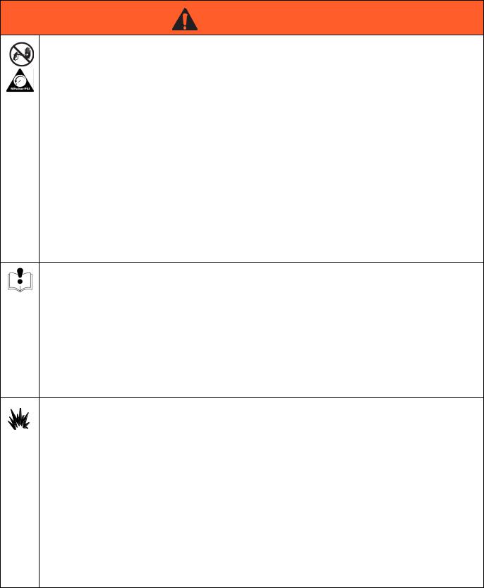
The following warnings are for the setup, use, maintenance, and repair of this equipment. The exclamation point symbol alerts you to a general warning and the hazard symbols refer to procedure-specific risks. When these symbols appear in the body of this manual or on warning labels, refer back to these Warnings. Product-specific hazard symbols and warnings not covered in this section may appear throughout the body of this manual where applicable.
 WARNING
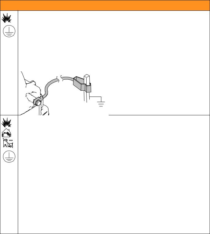
FIRE AND EXPLOSION HAZARD (GROUNDING)
Some oil-based and flammable materials generate static electricity when sprayed. Static electricity creates an explosion and fire risk. Your sprayer has a ground wire that will conduct the static electricity to earth ground. The sprayer and all objects in spray area must be properly grounded to protect against static discharge, sparks or shocks.
•Connect the ground wire when spraying flammable or static producing oil-based materials.
•If there is static sparking or if you feel a shock, stop spraying immediately and connect the sprayer to earth ground with the ground wire provided.
GROUNDING INSTRUCTIONS
Clamp sprayer ground wire to earth ground.
ti19343a
FIRE AND EXPLOSION HAZARD
Flammable fumes, such as solvent and paint fumes, in work area can ignite or explode. To help prevent fire and explosion:
• Do not spray flammable or combustible liquids in a confined area.
• Keep spray area well-ventilated. Keep a good supply of fresh air moving through the area.
• Paint or solvent flowing through the sprayer is able to result in static electricity. Static electricity creates a risk of fire or explosion in the presence of paint or solvent fumes. The sprayer and all objects in spray area shall be properly grounded to protect against static discharge, sparks, or shocks.
•Always connect the ground wire provided when spraying flammable materials or static producing oil-based materials. See Grounding Instructions above.
•If there is static sparking or you feel a shock, stop operation immediately and connect sprayer to earth ground with the ground wire provided.
•Do not spray flammable or combustible materials near open flame or sources of ignition such as cigarettes, external motors, and electrical equipment.
•Do not operate light switches, engines, or similar spark producing products in the spray area.
•Do not smoke in the spray area.
•Keep spray area clean and free of paint or solvent containers, rags, and other flammable materials.
•Know the contents of the paints and solvents being sprayed. Read all Material Safety Data Sheets (MSDS) and container labels provided with the paints and solvents. Follow the paint and solvents manufacturer’s safety instructions.
•Fire extinguisher equipment shall be present and working.
3A2308C |
3 |
Warnings
 WARNING
SKIN INJECTION HAZARD
High-pressure spray is able to inject toxins into the body and cause serious bodily injury. In the event that injection occurs, get immediate surgical treatment.
•Do not aim the sprayer at, or spray any person or animal.
•Keep hands and other body parts away from the discharge. For example, do not try to stop leaks with any part of the body.
•Always engage the trigger lock when not spraying. Verify the trigger lock is functioning properly.
•Always use the spray tip guard. Do not spray without spray tip guard in place.
•Use caution when cleaning and changing spray tips. In the case where the spray tip clogs while spraying, follow the Pressure Relief Procedure for relieving the pressure before reversing or removing the spray tip to clean.
•Do not leave the unit energized or under pressure while unattended. When the unit is not in use, follow the Pressure Relief Procedure and engage the trigger lock.
•Check parts for signs of damage. Replace any damaged parts with genuine Graco parts.
•This system is capable of producing 4000 psi. Use replacement parts or accessories that are rated a minimum of 4000 psi.
•Do not carry the sprayer with a finger on the trigger.
•Verify that all connections are secure before operating the unit.
•Know how to stop the unit and bleed pressure quickly. Be thoroughly familiar with the controls.
EQUIPMENT MISUSE HAZARD
Misuse can cause death or serious injury.
•Disconnect the battery before servicing.
•Always wear appropriate gloves, eye protection, and a respirator or mask when painting.
•Do not operate or spray near children. Keep children away from equipment at all times.
•Do not overreach or stand on an unstable support. Keep effective footing and balance at all times.
•Stay alert and watch what you are doing.
•Do not operate the unit when fatigued or under the influence of drugs or alcohol.
•Use only in dry locations. Do not expose to water or rain.
•Use in well-lit areas.
•Always replace cracked, broken or missing parts immediately with genuine Graco parts. See Parts List, page 23.
BATTERY HAZARD
The battery may leak, explode, cause burns, or cause an explosion if mishandled. Contents of an open battery can cause severe irritation and/or chemical burns. If on skin, wash with soap and water. If in eyes, flush with water for at least 15 minutes and seek immediate medical attention.
•Replace battery only in a well-ventilated area and away from flammable or combustible materials; including paints and solvents.
•When battery is not in use, keep it away from metal objects like keys, nails, screws or other metal objects that can short circuit the battery terminals.
•Do not throw into fire.
•Charge only with Graco-approved charger as listed in this manual.
•Do not store at temperatures below 32° or above 113° F (0° to 45° C).
•Do not use at temperatures below 40° or above 90° F (4° to 32° C).
•Do not expose battery to water or rain.
•Do not disassemble, crush, or penetrate the battery.
•Do not charge a battery that is cracked or damaged.
•Follow local ordinances and/or regulations for disposal.
4 |
3A2308C |

Warnings
 WARNING
CHARGER ELECTRIC SHOCK, FIRE AND EXPLOSION HAZARD
Improper setup or usage can cause electric shock, fire, and explosion.
•Charge only in a well-ventilated area and away from flammable or combustible materials, including paints and solvents.
•Do not charge on a combustible or flammable surface.
•Do not leave battery unattended while charging.
• Immediately unplug charger and remove battery when charging is complete.
• Charge only Graco batteries listed in this manual; other batteries may burst.
•Use only in dry locations. Do not expose to water or rain.
• Do not use a charger that is cracked or damaged.
• If the supply cord is damaged, replace the charger or cord, depending on model.
•Never force the battery into the charger.
•When operating a charger outdoors, always provide a dry location and use an extension cord suitable for outdoor use.
•Disconnect the charger from the outlet before cleaning.
•Ensure that the outside surface of the battery is clean and dry before plugging into the charger.
•Do not attempt to charge non-rechargeable batteries.
•Do not disassemble the charger. Take charger to authorized service center when service or repair is required.
PRESSURIZED ALUMINUM PARTS HAZARD
Use of fluids that are incompatible with aluminum in pressurized equipment can cause serious chemical reaction and equipment rupture. Failure to follow this warning can result in death, serious injury, or property damage.
•Do not use 1,1,1-trichloroethane, methylene chloride, other halogenated hydrocarbon solvents or fluids containing such solvents.
•Many other fluids may contain chemicals that can react with aluminum. Contact your material supplier for compatibility.
TOXIC FLUID OR FUMES HAZARD
Toxic fluids or fumes can cause serious injury or death if splashed in the eyes or on skin, inhaled, or swallowed.
•Read MSDS’s to know the specific hazards of the fluids you are using.
•Store hazardous fluid in approved containers, and dispose of it according to applicable guidelines.
PERSONAL PROTECTIVE EQUIPMENT
Wear appropriate protective equipment when in the work area to help prevent serious injury, including eye injury, hearing loss, inhalation of toxic fumes, and burns. This protective equipment includes but is not limited to:
•Protective eyewear, and hearing protection.
•Respirators, protective clothing, and gloves as recommended by the fluid and solvent manufacturer.
3A2308C |
5 |
Component Identification
Component Identification
A |
B |
C |
R |
|
|
|
|
D |
P |
|
E |
|
|
|
|
|
F |
N |
|
|
|
|
G |
M |
|
H |
|
|
|
|
K |
J |
|
|
ti19345a |
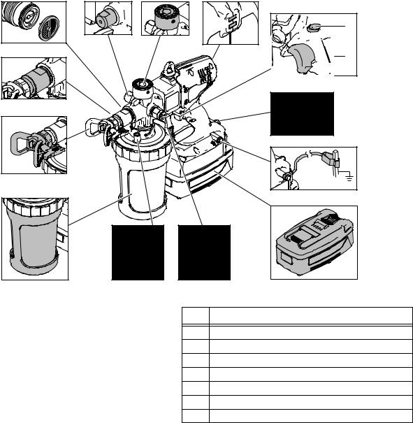
Ref. |
Description |
|
|
|
|
A |
Accumulator |
|
|
B |
Pressure Control Knob |
|
|
C |
Sprayer Status Indicator |
|
|
D |
Trigger Lock |
|
|
E |
Trigger |
|
|
F |
Static Wick |
|
|
G |
Ground Wire Assembly with Clamp |
|
|
Ref. |
Description |
H |
Battery |
J |
Pressure Relief Valve / Prime Valve |
K |
Check Valve |
M |
Material Cup |
N |
Spray Tip Assembly |
P |
Front Shut-Off Valve |
R |
Material Filter |
6 |
3A2308C |
Operation
Operation
Charging the Battery
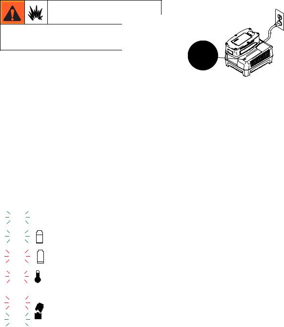
Replace and charge battery only in a well-ventilated area and away from flammable or combustible materials, including paints and solvents.
Batteries are initially 50% charged to provide optimum battery life and require charging before first use. It takes approximately 50 minutes to charge a dead battery to 80%, at which point it can be used. It will take approximately 75 minutes to fully charge a dead battery.
1.Place charger in a dry, well-ventilated area and away from flammable or combustible materials, including paints and solvents.
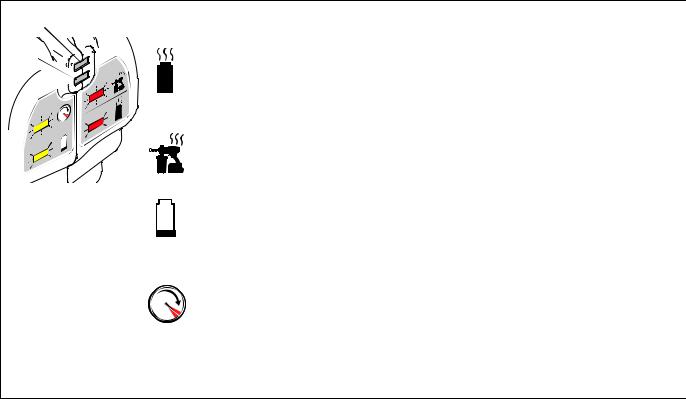
2.Plug charger into an electrical outlet and slide battery into charger as shown (light will turn on in 5 seconds).
ti19341a
3.When battery becomes fully charged, immediately unplug the charger from the power supply and remove the battery from the charger.
NOTE: The amount sprayed with each battery varies depending on material, spray tip size, battery charge, and battery temperature. One battery fully charged will spray up to one gallon. Amount sprayed will be less depending on spray tip size, material sprayed, life of battery, temperature, and other environmental factors.
Charger Status Indicator Lights
|
Label |
Appearance |
Description |
|||||
|
|
|
|
|
|
|
|
|
|
|
|
|
|
|
|
|
|
|
|
|
|
|
|
|
Solid green light |
Indicates a full charge. Battery can be used. |
|
|
|
|
|
|
|
||
|
|
|
|
|
|
|
|
|
|
|
|
|
|
|
|
|
|
|
|
|
|
|
|
|
Flashing green light |
Battery is charging, indicates 80% charge. |
|
|
|
|
|
|
|
Battery can be used. |
|
|
|
|
|
|
|
|
|
|
|
|
|
|
|
|
|
|
|
|
|
|
|
|
|
|
Flashing red light |
Battery is charging, indicates less than 80% charge. |
|
|
|
|
|
|
|
Do NOT use battery. |
|
|
|
|
|
|
|
|
|
|
|
|
|
|
|
|
|
|
|
|
|
|
|
|
|
|
|
Battery is too hot or too cold to charge. Remove battery and allow to cool or |
|
|
|
|
|
|
|
Solid red light |
warm up before charging. Battery temperature must be between |
|
|
|
|
|
|
|
|
50° F - 113° F (10° C - 45° C) to charge. |
|
|
|
|
|
|
|
|
|
|
|
|
|
|
|
|
Both lights |
Battery has internal fault or has experienced damage. Do not use. |
|
|
|
|
|
|
|
||
|
|
|
|
|
|
|
||
|
|
|
|
|
|
|
|
|
|
|
|
|
|
|
|
|
|
|
|
|
|
|
|
|
|
|
3A2308C |
7 |
Operation
Sprayer Status Indicator
Red
Yellow
|
|
|
No light |
Normal operation. |
No action required. |
|
|
|
|
|
|
|
|
|
|
Battery is too hot. Unit will |
Change battery. |
|
|
|
|
shut down until battery has |
|
|
|
|
|
Allow battery to cool. |
|
|
|
|
Solid Red |
cooled. |
|
|
|
|
|
||
|
|
|
|
|
|
|
|
|
|
Liquid has contacted control |
Allow unit to dry. |
|
|
|
|
board. |
|
|
|
|
|
|
|
|
|
|
|
|
|
|
|
|
|
Motor is too hot and will shut |
Increase tip size. |
|
|
|
|
down if heavy use continues. |
|
|
|
|
Flashing Red |
Turn down pressure. |
|
|
|
|
Unit will shut down until motor |
||
|
|
|
|
Let unit cool down. |
|
ti19361a |
|
|
|
has cooled. |
|
|
|
|
|
|
|
|
|
|
Battery is low or |
Charge battery. |
|
|
|
|
|
||
|
|
|
Solid Yellow |
|
|
|
|
|
|
||
|
|
|
battery is too cold. |
Warm up battery. |
|
|
|
|
|
||
|
|
|
|
|
|
|
|
|
|
|
|
|
|
|
|
|
Turn pressure control |
|
|
|
|
|
counter-clockwise to reduce |
|
|
|
Flashing Yellow |
High pressure signal. Gun will |
pressure. |
|
|
|
shut down after 1.5 seconds. |
Increase tip size. |
|
|
|
|
|
||
|
|
|
|
|
|
|
|
|
|
|
Material is too thin--do not thin |
|
|
|
|
|
as much. |
|
|
|
|
|
|
|
Solid red and solid yellow |
Locked motor. |
Bring sprayer in to service cen- |
||
|
ter for diagnostics. |
||||
|
|
|
|
|
|
|
|
|
|
|
|
*NOTE: The sprayer status indicator light is visible for 10 seconds after the trigger is released.
8 |
3A2308C |
Operation
Common Procedures
Trigger Lock
Follow the Pressure Relief Procedure whenever you see this symbol.
Always engage the trigger lock when you stop spraying to prevent the sprayer from being triggered accidentally by hand, or if dropped or bumped.
ti19350a
Trigger Locked
ti19374a
Trigger Unlocked (red ring is visible)
Prime/Pressure Relief Valve Position
Pressure Relief Procedure
Do not operate or spray near children. Do not aim the sprayer at, or spray any person or animal. Keep hands and other body parts away from the discharge. For example, do not try to stop the paint flow with any part of the body.
This sprayer builds up an internal pressure of 4000 psi during use. This equipment stays pressurized until pressure is manually relieved. To help prevent serious injury from pressurized fluid, such as skin injection, splashing fluid and moving parts, follow the Pressure Relief Procedure when you stop spraying and before cleaning, checking, or servicing the equipment.
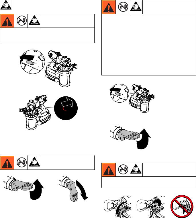
1. Engage trigger lock.
ti19350a
2.Put prime/pressure relief valve UP to release pressure.
ti19347a
Spray Tip Position
Always perform Pressure Relief Procedure before adjusting spray tip position.
|
ti19346a |
ti19347a |
|
UP position |
DOWN position |
(For priming and releasing |
(Ready to spray) |
pump pressure) |
|
ti14ti19371a85a |
ti14ti19370a91a |
|
Tip Forward |
Tip Reversed |
ti15510a |
(SPRAY position) |
(UNCLOG position) |
|
3A2308C |
9 |
Operation
Adjusting Pressure
NOTE: Spraying water, solvents, and thin materials (low viscosity materials) at high pressure (setting “2” or higher with yellow light flashing) can result in temporary pump leaking. To avoid, read and follow instructions (Quick Guide or Manual) on how to properly adjust pressure.
NOTE: To reduce overspray and extend battery life, always spray at lowest pressure that results in an acceptable spray pattern.
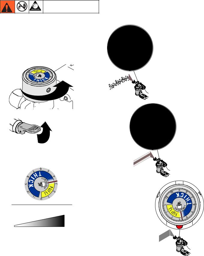
4.You MUST start with dial at “1” and gradually increase by increments of “1” or less until desired spray pattern is achieved. Put pressure relief handle in UP position to turn pressure control knob, then return handle to DOWN position to spray.
ti19353a
ti19372a
1. Put the pressure relief valve UP to relieve pressure.
ti19347a
2. Turn pressure control knob:
Clockwise to INCREASE pressure, or Counter-clockwise to DECREASE pressure.
ti19408a
THIN |
THICK |
MATERIAL |
MATERIAL |
ti19407a
0 1 2 3 4 5 6 7 8 9 10 11
3. Dial in pressure by spraying material on a scrap material.
ti19409a
10 |
3A2308C |
Operation
5.If yellow light is flashing while triggering, pressure is set too high. You MUST turn down pressure until yellow light no longer flashes, increase tip size, or do not thin material as much.
6.If pressure relief valve is vibrating, pressure is set too high. You MUST turn down pressure, increase tip size, or do not thin material as much.
ti19655a
ti19656a
ti19654a
ti19653a
NOTE: Thin materials will generally require a low setting and thick materials will generally require a high setting.
IMPORTANT!
After storage, the piston seals need to be energized prior to next use to prevent leakage. To energize, follow steps below:
1.Prime system with flushing fluid.
2.Spray at low pressure setting “1” for 10 seconds.
3.Drain fluid. You are now ready to spray.
3A2308C |
11 |
Setup
Flammable fumes (such as solvent and paint fumes) in work area can ignite or explode.
See Grounding Instructions, page 3.
Do not spray flammable or combustible liquids in a confined area.
Keep spray area well-ventilated. Keep a good supply of fresh air moving through the area.
Operation
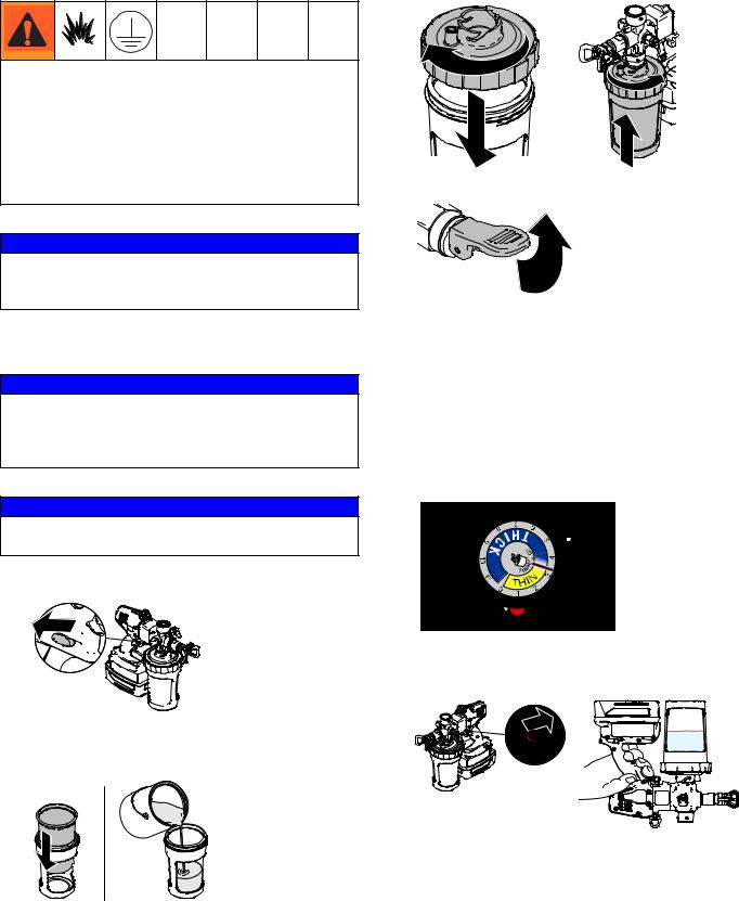
3. Thread lid onto cup and connect cup to sprayer.
ti19354a |
ti19384a |
4. Put prime/pressure relief valve in UP position.
NOTICE
Your sprayer is NOT compatible with harsh cleaners such as chlorine bleach. Using these cleaners will cause damage to the sprayer.
Starting a New Job
NOTICE
Always flush any cleaning material from the previous use before starting a new job. If the new spraying material is not compatible with leftover material in the pump, adverse reactions could ruin new material.
NOTICE
Do NOT spray zinc coatings or materials with aggregate. Accelerated pump wear will occur.
1. Engage trigger lock.

 ti19350a
2.Install liner into cup and fill liner 1/2 full with appropriate cleaning fluid for material about to be sprayed.
ti19348a
ti19347a
NOTE: After storage, the piston seals need to be energized prior to next use to prevent leakage. To energize, follow steps below:
a.Prime system with flushing fluid.
b.Spray at low pressure setting “1” for 10 seconds.
c.Drain fluid. You are now ready to spray.
5.You MUST set pressure control to setting “1”.
6.Disengage trigger lock, turn sprayer upside-down and trigger for approximately 5 seconds to recirculate material.
ti19374a
12 |
3A2308C |
Operation
7.Reverse tip to UNCLOG position. Put prime/pressure relief valve DOWN to spray position and trigger sprayer through tip into waste area for 1- 2 seconds.
ti19370a ti19346a
ti19366a
8.Engage trigger lock and put prime/pressure relief valve UP to release pressure.
ti19347a
ti19350a
9.Remove material cup.
10.Disengage trigger lock, put prime/pressure relief valve DOWN to spray position, hold sprayer slightly above material cup and pull trigger to discharge fluid from pump.
ti19403a
11.Put prime/pressure relief valve UP and pull trigger to finish flushing material.
ti19401a
12. Properly discard any material in cup.
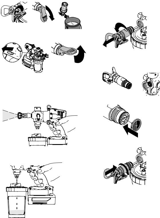
Install/Service Filter (if needed)
1.Perform Pressure Relief Procedure, page 9.
2.Unthread front valve housing from sprayer.
ti19362a
3.Filter should come out of pump housing with valve. If filter remains in housing, remove it by hand or with pliers if necessary.
ti19342a 


4. Install properly-sized filter (if needed).
ti19349a
5. Reassemble valve housing to pump.
ti19364a
3A2308C |
13 |

Install Tip/Guard Assembly (if not installed)
NOTE: Only use Graco Tip/Guard assemblies.
This equipment stays pressurized until pressure is manually relieved. To help prevent serious injury from pressurized fluid, such as skin injection, splashing fluid and moving parts, follow the Pressure Relief Procedure when you stop spraying and before cleaning, checking, or servicing the equipment.
1.Engage trigger lock and put prime/pressure relief valve UP to relieve pressure.
ti19350a |
ti19347a |
Do NOT place hands in front of tip.
2.Screw Tip/Guard Assembly onto sprayer. Tighten retaining nut until completely engaged with sprayer. Do not overtighten nut.
ti19369a
Filling and Installing Cup
1.Engage trigger lock and put prime/pressure relief valve UP to relieve pressure.
Operation
2. Install liner into material cup and fill with material.
ti19348a
3.Thread lid onto material cup and connect cup to sprayer. NOTE: Do not squeeze sides of cup while threading lid onto cup.
ti19354a |
ti19384a |
NOTE: Check valve can be oriented in three locations when attached to cup. If squeezing liner with left hand, position check valve on left side. If squeezing liner with right hand, position check valve on right side.
ti19355a
4.Squeeze liner to purge air through check valve until material is present at check valve.
|
ti19367a |
ti19350a |
ti19347a |
NOTE: To purge the maximum amount of air out of the liner, slightly tilt the sprayer so the check valve is the highest point.
14 |
3A2308C |
Loading...