


 Loading...
GPS 24XD NMEA 2000®
INSTALLATION
INSTRUCTIONS
Important Safety Information
 CAUTION
To avoid possible personal injury, always wear safety goggles, ear protection, and a dust mask when drilling, cutting, or sanding.
NOTICE
When drilling or cutting, always check what is on the opposite side of the surface to avoid damaging the vessel.
For the best performance and to avoid damage to your boat, read all installation instructions before proceeding. Install the device per these instructions. Use the appropriate fasteners, tools, and mounts listed, which are available at most marine dealers.
The Garmin® GPS 24xd NMEA 2000 high-sensitivity GPS antenna provides position information to your existing NMEA 2000 network. If your boat does not have a NMEA 2000 network, you will need to install one.
For more information, go to www.garmin.com.
Tools Needed
•Drill
•3.2 mm (1/8 in.) drill bit
•19 mm (3/4 in.) drill bit for a pole-mount cable-hole
•1 in. (25 mm) hole saw for a surface-mount cable-hole
•Countersink bit for mounting on fiberglass
•Screws for under-deck mounting
•Screwdriver, appropriate for the screw type
•Marine sealant (optional)
•Additional NMEA 2000 network components as needed
Mounting the Antenna
Antenna Mounting Considerations
 CAUTION
Do not install or store the antenna near strong magnets, including speakers. A strong magnetic field can damage the antenna.
You can mount the antenna on a flat surface or attach it to a standard 1 in. OD, 14 threads per inch, pipe-threaded pole (not included). You can route the cable outside of the pole or through the pole. For best performance, consider these guidelines when selecting the antenna mounting location.
•To ensure the best reception, the antenna should be mounted in a location that has a clear, unobstructed view of the sky in all directions  .
.
•The antenna should not be mounted where it is shaded by
the superstructure of the boat  , a radome antenna, or the mast.
•The antenna should not be mounted near the engine or other sources of Electromagnetic Interference (EMI)  .
.
•The antenna should not be mounted near known ferrous metal objects such as a toolbox or compass.
•A handheld compass should be used to test for magnetic interference in the area where the antenna is to be mounted. Your boat, motors, and devices must be on during the test.
If the needle on the handheld compass moves when you hold it where you intend to mount the antenna, magnetic interference is present. You must choose another location and test again.
•Mounting screws are provided with the antenna. If you use mounting hardware other than the provided screws, the hardware must be made of quality stainless steel or brass material to avoid magnetic interference with the antenna.
NOTE: Test all mounting hardware with a handheld compass to make sure no magnetic fields are present in the hardware.
•If a radar is present, the antenna should be mounted above the path of the radar  . If necessary, the antenna may be mounted below the path of the radar
  .
.
•The antenna should not be mounted directly in the path of the radar  .
.
•The antenna should not be mounted within 1 m (3 ft.) of a VHF radio antenna or the path of a radar  .
.
Testing the Mounting Location
1Temporarily secure the antenna in the preferred mounting location and test it for correct operation.
2If you experience interference with other electronics, move the antenna to a different location, and test it again.
August 2020 |
GUID-28CE8C25-CFD8-4C12-B6D0-AD9CDF4D5084 v2 |
3Repeat steps 1–2 until you observe full or acceptable signal strength.
4 Permanently mount the antenna.
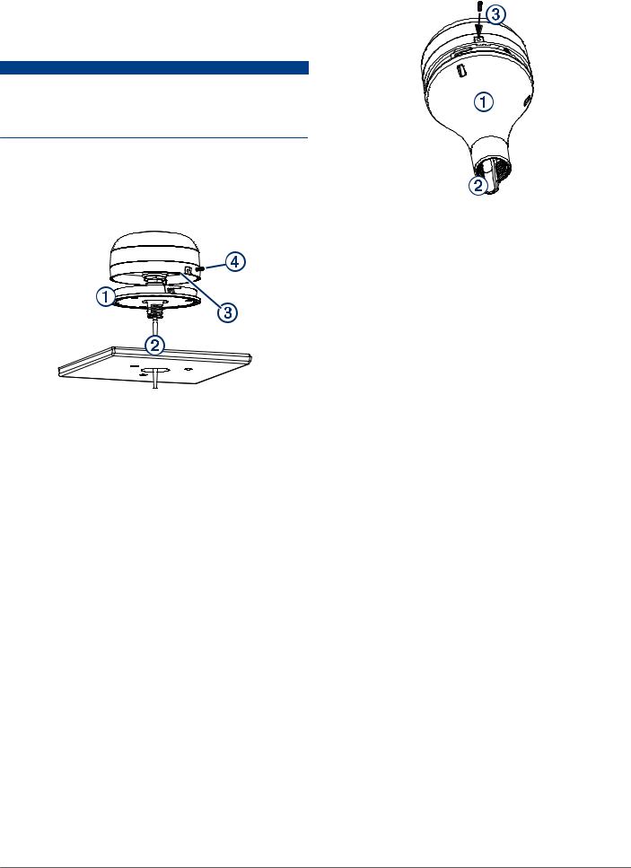
Surface Mounting the Antenna
NOTICE
If you are mounting the bracket on fiberglass with screws, it is recommended to use a countersink bit to drill a clearance counterbore through only the top gel-coat layer. This will help to avoid cracking in the gel-coat layer when the screws are tightened.
Before you permanently mount the antenna, you must test the mounting location for correct operation (Testing the Mounting Location, page 1).
1Using the surface-mount bracket  as your mounting template, mark the three pilot-hole locations and trace the cable-hole in the center of the bracket.
2Set the surface-mount bracket aside. Do not drill through the bracket.
3 Drill the three 3.2 mm (1/8 in.) pilot holes.
4 Drill the 19 mm (3/4 in.) cable hole in the center.
5Use the included M4 screws to secure the surface-mount bracket to the mounting surface.
6Route the cable  through the center hole, and connect it to the antenna.
7Verify the large gasket  is in place on the bottom of the antenna, place the antenna on the surface-mount bracket, and twist it clockwise to lock it in place.
8Secure the antenna to the mounting bracket with the included M3 screw  .
.
9 Route the cable away from sources of electronic interference.
Mounting the Antenna on a Pole
Mounting the Antenna with the Cable Routed Outside the Pole
Before you permanently mount the antenna, you must test the mounting location for correct operation (Testing the Mounting Location, page 1).
1Route the cable through the pole-mount adapter  , and place the cable in the vertical slot
  along the base of the pole-mount adapter.
2Screw the pole-mount adapter onto a standard 1 in. OD, 14 threads per inch, pipe-threaded pole (not included).
Do not overtighten the adapter on the pole.
3 Connect the cable to the antenna.
4Place the antenna on the pole-mount adapter and twist it clockwise to lock it in place.
5Secure the antenna to the adapter with the included M3 set screw  .
.
6With the antenna installed on the pole mount, fill the remaining gap in the vertical cable slot with a marine sealant (optional).
7 Attach the pole to the boat if it is not already attached.
8 Route the cable away from sources of electronic interference.
Mounting the Antenna with the Cable Routed Through the Pole
Before you permanently mount the antenna, you must test the mounting location for correct operation (Testing the Mounting Location, page 1).
1Position a standard 1 in. OD, 14 threads per inch, pipethreaded pole (not included) in the selected location, and mark the approximate center of the pole.
2Drill a hole using a 19 mm (3/4 in.) drill bit for the cable to pass through.
3 Fasten the pole to the boat.
4Thread the pole-mount adapter onto the pole. Do not overtighten the adapter.
5Route the cable through the pole and connect it to the antenna.
6Place the antenna on the pole-mount adapter and twist it clockwise to lock it in place.
7Secure the antenna to the adapter with the included M3 set screw  .
.
2
Loading...