


16 i -LA
Table of contents
 Loading...
GE Fanuc Automation
Computer Numerical Control Products
Series 16 i / 160 i–LA
Connection Manual
GFZ-63193EN/02 August 2000

Warnings, Cautions, and Notes
as Used in this Publication
Warning notices are used in this publication to emphasize that hazardous voltages, currents,
temperatures, or other conditions that could cause personal injury exist in this equipment or may
be associated with its use.
In situations where inattention could cause either personal injury or damage to equipment, a
Warning notice is used.
Caution notices are used where equipment might be damaged if care is not taken.
GFL-001
Warning
Caution
Note
Notes merely call attention to information that is especially significant to understanding and
operating the equipment.
This document is based on information available at the time of its publication. While efforts
have been made to be accurate, the information contained herein does not purport to cover all
details or variations in hardware or software, nor to provide for every possible contingency in
connection with installation, operation, or maintenance. Features may be described herein which
are not present in all hardware and software systems. GE Fanuc Automation assumes no
obligation of notice to holders of this document with respect to changes subsequently made.
GE Fanuc Automation makes no representation or warranty, expressed, implied, or statutory
with respect to, and assumes no responsibility for the accuracy, completeness, sufficiency, or
usefulness of the information contained herein. No warranties of merchantability or fitness for
purpose shall apply.
©Copyright 2000 GE Fanuc Automation North America, Inc.
All Rights Reserved.

B–63193EN/02
PREFACE
PREFACE
The following three connection manuals are prepared for F ANUC Series
16i–LA and Series 160i–LA:
Manual name
FANUC Series 16i/18i/160i/180i–MODEL A
CONNECTION MANUAL (Hardware)
FANUC Series 16i/18i/21i/160i/180i/210i–MODEL A
CONNECTION MANUAL (Function)
FANUC Series 16i/160i–LA CONNECTION MANUAL B–63193EN *
Specification
number
B–63003EN
B–63003EN–1
The “Hardware” and “Function” connection manuals provide general
connection information relating to the configuration of a processing
system.
FANUC Series 16i/160i–LA CONNECTION MANUAL provides
supplementary information about the laser functions which are not
explained in the above two connection manuals (“Hardware” and
“Function”).
In addition to the above connection manuals, laser oscillator manuals are
available. Refer to these manuals as necessary.
The laser functions are explained as described below.
1. Overview
This section outlines the various functions. For details, refer to the
operator’s manual as necessary.
2. Signal
Explains the names, functions, output conditions, and signal addresses
of the signals required to implement each function.
3. Parameters
Explains the parameters related to each function.
4. Alarms and messages
Lists the alarms and messages related to each function.
5. Reference
Lists the related manuals and items.
An address list and signal list are provided in the appendixes of this
manual. Refer to these appendixes as necessary.
p–1

PREFACE
B–63193EN/02
Applicable product
S Representation of bit
type and bit–axis type
parameters
S Representation of
parameters other than bit
type and bit–axis type
parameters
Related manuals
This manual explains the following product. In the manual, the following
abbreviation may be used.
Product name Abbreviations
FANUC Series 16i–LA 16i–LA
FANUC Series 160i–LA 160i–LA
Data (#0 to #7 indicate bit positions.)
Data No.
0000
Data No. Data
1023
#7
#6 #5
SEQ
#4 #3 #2
INI
#1
ISO#0TVC
The table below lists manuals related to FANUC series 16i–LA. In the
table, this manual is marked with an asterisk (*).
Manual name
FANUC Series 16i/18i/21i/160i/180i/210i–MODEL A
DESCRIPTIONS
Specification
number
B–63002EN
Re-
marks
FANUC Series 16i/18i/21i/20i/160i/180i/210i–
MODEL A CONNECTION MANUAL (Hardware)
FANUC Series 16i/18i/21i/160i/180i/210i–MODEL A
CONNECTION MANUAL (Function)
FANUC Series 16i/18i/160i/180i–MODEL A
P ARAMETER MANUAL
FANUC Series 16i/160i–LA DESCRIPTIONS B–63192EN
FANUC Series 16i/160i–LA CONNECTION MANUAL B–63193EN *
FANUC Series 16i/160i–LA OPERATOR’S MANUAL B–63194EN
FANUC Series 16i/160i–LA
MAINTENANCE MANUAL
FANUC Series 16i/160i–LA PARAMETER MANUAL B–63200EN
FANUC Series 16/18/20/21
PROGRAMMING MANUAL
(Macro compiler/Macro Executer)
FAPT MACRO COMPILER
PROGRAMMING MANUAL
B–63003EN
B–63003EN–1
B–63010EN
B–63195EN
B–61803E–1
B–66102E
p–2

B–63193EN/02
Table of Contents
PREFACE p–1. . . . . . . . . . . . . . . . . . . . . . . . . . . . . . . . . . . . . . . . . . . . . . . . . . . . . . . . . . . . . . . . . . .
I. HARDWARE
1. OVERVIEW 3. . . . . . . . . . . . . . . . . . . . . . . . . . . . . . . . . . . . . . . . . . . . . . . . . . . . . . . . . . . . . . . . . .
1.1 DIFFERENCES BETWEEN Series 16i–LA AND Series 16i 4. . . . . . . . . . . . . . . . . . . . . . . . . . . . . . .
1.2 DIFFERENCES BETWEEN Series 16i–LA AND Series 16–LB 4. . . . . . . . . . . . . . . . . . . . . . . . . . . .
2. CONFIGURATION 5. . . . . . . . . . . . . . . . . . . . . . . . . . . . . . . . . . . . . . . . . . . . . . . . . . . . . . . . . . . .
3. CONTROL UNIT 6. . . . . . . . . . . . . . . . . . . . . . . . . . . . . . . . . . . . . . . . . . . . . . . . . . . . . . . . . . . . . .
3.1 CONFIGURATION OF THE CONTROL UNIT 7. . . . . . . . . . . . . . . . . . . . . . . . . . . . . . . . . . . . . . . . .
4. TOTAL CONNECTION DIAGRAM 8. . . . . . . . . . . . . . . . . . . . . . . . . . . . . . . . . . . . . . . . . . . . . .
5. POWER SUPPLY 1 1. . . . . . . . . . . . . . . . . . . . . . . . . . . . . . . . . . . . . . . . . . . . . . . . . . . . . . . . . . . .
5.1 CONTROL UNIT POWER SUPPLY 12. . . . . . . . . . . . . . . . . . . . . . . . . . . . . . . . . . . . . . . . . . . . . . . . .
6. I/O LIMITATION BASED ON LASER OSCILLATOR CONNECTION 14. . . . . . . . . . . . . . .
7. LASER OSCILLATOR 15. . . . . . . . . . . . . . . . . . . . . . . . . . . . . . . . . . . . . . . . . . . . . . . . . . . . . . .
7.1 CONNECTION OF THE LASER OSCILLATOR 16. . . . . . . . . . . . . . . . . . . . . . . . . . . . . . . . . . . . . . .
7.1.1 Connection of the Adaptor 16. . . . . . . . . . . . . . . . . . . . . . . . . . . . . . . . . . . . . . . . . . . . . . . . . . . . .
7.2 LASER OSCILLATOR CONNECTION USING AN OPTICAL FIBER CABLE 17. . . . . . . . . . . . . . .
7.3 ASSIST GAS PRESSURE ANALOG OUTPUT 18. . . . . . . . . . . . . . . . . . . . . . . . . . . . . . . . . . . . . . . .
7.4 CONNECTION OF THE TRACING SENSOR 20. . . . . . . . . . . . . . . . . . . . . . . . . . . . . . . . . . . . . . . . .
II. LASER FUNCTION
1. FUNCTIONS 23. . . . . . . . . . . . . . . . . . . . . . . . . . . . . . . . . . . . . . . . . . . . . . . . . . . . . . . . . . . . . . .
2. FUNCTIONS DIFFERING FROM THE M SERIES SPECIFICATIONS 30. . . . . . . . . . . . .
2.1 EMERGENCY STOP 31. . . . . . . . . . . . . . . . . . . . . . . . . . . . . . . . . . . . . . . . . . . . . . . . . . . . . . . . . . . . .
2.2 FEED HOLD 31. . . . . . . . . . . . . . . . . . . . . . . . . . . . . . . . . . . . . . . . . . . . . . . . . . . . . . . . . . . . . . . . . . . .
2.3 TEST OPERATION 32. . . . . . . . . . . . . . . . . . . . . . . . . . . . . . . . . . . . . . . . . . . . . . . . . . . . . . . . . . . . . . .
2.3.1 Machine Lock 32. . . . . . . . . . . . . . . . . . . . . . . . . . . . . . . . . . . . . . . . . . . . . . . . . . . . . . . . . . . . . . .
2.3.2 Dry Run 32. . . . . . . . . . . . . . . . . . . . . . . . . . . . . . . . . . . . . . . . . . . . . . . . . . . . . . . . . . . . . . . . . . . .
2.3.3 Single Block 33. . . . . . . . . . . . . . . . . . . . . . . . . . . . . . . . . . . . . . . . . . . . . . . . . . . . . . . . . . . . . . . .
2.4 PROGRAM RESTART (LASER SPECIFICATIONS) 34. . . . . . . . . . . . . . . . . . . . . . . . . . . . . . . . . . . .
3. LASER SEQUENCE CONTROL 37. . . . . . . . . . . . . . . . . . . . . . . . . . . . . . . . . . . . . . . . . . . . . .
3.1 SEQUENCE CONTROL OF THE C SERIES AND Y SERIES LASER OSCILLATORS 38. . . . . . . .
c–1

TABLE OF CONTENTS
B–63193EN/02
4. ASSIST GAS 48. . . . . . . . . . . . . . . . . . . . . . . . . . . . . . . . . . . . . . . . . . . . . . . . . . . . . . . . . . . . . . .
4.1 ASSIST GAS CONTROL 49. . . . . . . . . . . . . . . . . . . . . . . . . . . . . . . . . . . . . . . . . . . . . . . . . . . . . . . . . .
4.2 ASSIST GAS PRESSURE ANALOG OUTPUT 57. . . . . . . . . . . . . . . . . . . . . . . . . . . . . . . . . . . . . . . .
4.3 ASSIST GAS PRESSURE OVERRIDE 59. . . . . . . . . . . . . . . . . . . . . . . . . . . . . . . . . . . . . . . . . . . . . . .
5. LASER OUTPUT CONTROL 60. . . . . . . . . . . . . . . . . . . . . . . . . . . . . . . . . . . . . . . . . . . . . . . . .
5.1 SHUTTER OPENING/CLOSING CONTROL 61. . . . . . . . . . . . . . . . . . . . . . . . . . . . . . . . . . . . . . . . . .
5.2 BEAM ON/OFF CONTROL 64. . . . . . . . . . . . . . . . . . . . . . . . . . . . . . . . . . . . . . . . . . . . . . . . . . . . . . . .
5.3 OUTPUT OVERRIDE 68. . . . . . . . . . . . . . . . . . . . . . . . . . . . . . . . . . . . . . . . . . . . . . . . . . . . . . . . . . . . .
5.3.1 Power Override Signal 68. . . . . . . . . . . . . . . . . . . . . . . . . . . . . . . . . . . . . . . . . . . . . . . . . . . . . . . .
5.3.2 Frequency Override Signal 69. . . . . . . . . . . . . . . . . . . . . . . . . . . . . . . . . . . . . . . . . . . . . . . . . . . . .
5.3.3 Duty Override 70. . . . . . . . . . . . . . . . . . . . . . . . . . . . . . . . . . . . . . . . . . . . . . . . . . . . . . . . . . . . . . .
5.4 CHANGING THE PIERCING TIME 72. . . . . . . . . . . . . . . . . . . . . . . . . . . . . . . . . . . . . . . . . . . . . . . . .
5.5 GUIDE LIGHT ON SIGNAL 75. . . . . . . . . . . . . . . . . . . . . . . . . . . . . . . . . . . . . . . . . . . . . . . . . . . . . . .
5.6 STATE OUTPUT SIGNAL 76. . . . . . . . . . . . . . . . . . . . . . . . . . . . . . . . . . . . . . . . . . . . . . . . . . . . . . . . .
5.6.1 Piercing Signal 76. . . . . . . . . . . . . . . . . . . . . . . . . . . . . . . . . . . . . . . . . . . . . . . . . . . . . . . . . . . . . .
5.6.2 Laser Processing Signal 77. . . . . . . . . . . . . . . . . . . . . . . . . . . . . . . . . . . . . . . . . . . . . . . . . . . . . . .
5.6.3 Output Drop Alarm Signal 78. . . . . . . . . . . . . . . . . . . . . . . . . . . . . . . . . . . . . . . . . . . . . . . . . . . . .
5.6.4 Laser Alarm Signal 79. . . . . . . . . . . . . . . . . . . . . . . . . . . . . . . . . . . . . . . . . . . . . . . . . . . . . . . . . . .
5.6.5 Laser Oscillator Not Connected Signal 81. . . . . . . . . . . . . . . . . . . . . . . . . . . . . . . . . . . . . . . . . . .
6. TRACING CONTROL 82. . . . . . . . . . . . . . . . . . . . . . . . . . . . . . . . . . . . . . . . . . . . . . . . . . . . . . .
6.1 TRACING CONTROL 83. . . . . . . . . . . . . . . . . . . . . . . . . . . . . . . . . . . . . . . . . . . . . . . . . . . . . . . . . . . .
6.1.1 Tracing Function 83. . . . . . . . . . . . . . . . . . . . . . . . . . . . . . . . . . . . . . . . . . . . . . . . . . . . . . . . . . . . .
6.1.2 Tracing Control Adjustment 86. . . . . . . . . . . . . . . . . . . . . . . . . . . . . . . . . . . . . . . . . . . . . . . . . . . .
6.1.3 Standard Shift 92. . . . . . . . . . . . . . . . . . . . . . . . . . . . . . . . . . . . . . . . . . . . . . . . . . . . . . . . . . . . . . .
6.1.4 Approach 94. . . . . . . . . . . . . . . . . . . . . . . . . . . . . . . . . . . . . . . . . . . . . . . . . . . . . . . . . . . . . . . . . . .
6.1.5 Tracing Alarm 96. . . . . . . . . . . . . . . . . . . . . . . . . . . . . . . . . . . . . . . . . . . . . . . . . . . . . . . . . . . . . . .
6.1.6 Tracing Gain Override 99. . . . . . . . . . . . . . . . . . . . . . . . . . . . . . . . . . . . . . . . . . . . . . . . . . . . . . . .
6.2 TRACING INTERLOCK SIGNAL 100. . . . . . . . . . . . . . . . . . . . . . . . . . . . . . . . . . . . . . . . . . . . . . . . . .
6.3 TRACING AXIS MACHINE LOCK 102. . . . . . . . . . . . . . . . . . . . . . . . . . . . . . . . . . . . . . . . . . . . . . . .
7. THREE–DIMENSIONAL MACHINING SYSTEM 103. . . . . . . . . . . . . . . . . . . . . . . . . . . . . . .
7.1 POSITION CONTROL 104. . . . . . . . . . . . . . . . . . . . . . . . . . . . . . . . . . . . . . . . . . . . . . . . . . . . . . . . . . .
7.1.1 Position Control A (Zero–offset Head) 105. . . . . . . . . . . . . . . . . . . . . . . . . . . . . . . . . . . . . . . . . . .
7.1.2 Position Control B (Offset Nozzle) 109. . . . . . . . . . . . . . . . . . . . . . . . . . . . . . . . . . . . . . . . . . . . . .
7.2 TEACHING BOX INTERFACE 121. . . . . . . . . . . . . . . . . . . . . . . . . . . . . . . . . . . . . . . . . . . . . . . . . . . .
7.3 W–AXIS TRACING 146. . . . . . . . . . . . . . . . . . . . . . . . . . . . . . . . . . . . . . . . . . . . . . . . . . . . . . . . . . . . .
7.4 TRACING FEED 149. . . . . . . . . . . . . . . . . . . . . . . . . . . . . . . . . . . . . . . . . . . . . . . . . . . . . . . . . . . . . . . .
7.5 APPROACH FEED 150. . . . . . . . . . . . . . . . . . . . . . . . . . . . . . . . . . . . . . . . . . . . . . . . . . . . . . . . . . . . . .
7.6 NEAR–POINT SEARCH FUNCTION 151. . . . . . . . . . . . . . . . . . . . . . . . . . . . . . . . . . . . . . . . . . . . . . .
7.7 HAND COORDINATE SYSTEM MODE SELECT SIGNAL 156. . . . . . . . . . . . . . . . . . . . . . . . . . . . .
8. CONTROL FUNCTION 159. . . . . . . . . . . . . . . . . . . . . . . . . . . . . . . . . . . . . . . . . . . . . . . . . . . . .
8.1 CONSTANT–OPTICAL PATH CONTROL 160. . . . . . . . . . . . . . . . . . . . . . . . . . . . . . . . . . . . . . . . . . .
c–2

B–63193EN/02
8.2 MACHINING CONDITION SETTING FUNCTION 167. . . . . . . . . . . . . . . . . . . . . . . . . . . . . . . . . . . .
8.3 PIERCING FUNCTION 177. . . . . . . . . . . . . . . . . . . . . . . . . . . . . . . . . . . . . . . . . . . . . . . . . . . . . . . . . .
8.4 EDGE MACHINING FUNCTION 180. . . . . . . . . . . . . . . . . . . . . . . . . . . . . . . . . . . . . . . . . . . . . . . . . .
8.5 START–UP FUNCTION 185. . . . . . . . . . . . . . . . . . . . . . . . . . . . . . . . . . . . . . . . . . . . . . . . . . . . . . . . . .
8.6 MACHINING RESTART FUNCTION 188. . . . . . . . . . . . . . . . . . . . . . . . . . . . . . . . . . . . . . . . . . . . . . .
8.7 LASER POWER CONTROL 201. . . . . . . . . . . . . . . . . . . . . . . . . . . . . . . . . . . . . . . . . . . . . . . . . . . . . .
8.8 LASER GAS MIXTURE FUNCTION 208. . . . . . . . . . . . . . . . . . . . . . . . . . . . . . . . . . . . . . . . . . . . . . .
8.9 REFLECTION BEAM MONITOR FUNCTION 214. . . . . . . . . . . . . . . . . . . . . . . . . . . . . . . . . . . . . . .
8.10 PULSE ENHANCED FUNCTION 215. . . . . . . . . . . . . . . . . . . . . . . . . . . . . . . . . . . . . . . . . . . . . . . . . .
8.11 AI CONTOUR CONTROL 216. . . . . . . . . . . . . . . . . . . . . . . . . . . . . . . . . . . . . . . . . . . . . . . . . . . . . . . .
TABLE OF CONTENTS
APPENDIX
A. INTERFACE BETWEEN CNC AND PMC 241. . . . . . . . . . . . . . . . . . . . . . . . . . . . . . . . . . . . .
A.1 LIST OF ADDRESSES 242. . . . . . . . . . . . . . . . . . . . . . . . . . . . . . . . . . . . . . . . . . . . . . . . . . . . . . . . . . .
A.2 LIST OF SIGNALS 243. . . . . . . . . . . . . . . . . . . . . . . . . . . . . . . . . . . . . . . . . . . . . . . . . . . . . . . . . . . . . .
A.2.1 List of Signals (In Order of Functions) 243. . . . . . . . . . . . . . . . . . . . . . . . . . . . . . . . . . . . . . . . . . .
A.2.2 List of Signals (In Order of Symbols) 245. . . . . . . . . . . . . . . . . . . . . . . . . . . . . . . . . . . . . . . . . . . .
A.2.3 List of Signals (In Order of Addresses) 248. . . . . . . . . . . . . . . . . . . . . . . . . . . . . . . . . . . . . . . . . .
c–3

I. HARDWARE

B–63193EN/02
1
1. OVERVIEWHARDWARE
OVERVIEW
3

1. OVERVIEW
HARDWARE
B–63193EN/02
1.1
DIFFERENCES BETWEEN Series 16i–LA AND Series 16i
1.2
DIFFERENCES BETWEEN Series 16i–LA AND Series 16–LB
Configure the Series 16i–LA system by making connections as described
in the “Series 16i Connection Manual.”
For an explanation of the differences between the Series 16i–LA and
Series 16i, refer to this manual as necessary.
The following table lists the differences between the Series 16i–LA
(FS16i–LA) and Series 16–LB (FS16–LB):
Feature FS16i–LA FS16–LB
Power to control unit 24 VDC 200 VAC
Control unit on/off
switch
Laser oscillator on/off
signal
External control
(Power supply for control
unit is controlled.)
24 VDC (Power supply for
control unit is connected.)
Internal control
(Control unit is provided
with on/off circuit.)
200 VAC (EXR and EXS
signals of input unit, or
200A and 200B signals of
power supply unit are
used.)
I/O LINK
Connectable
DI/DO
Laser
oscillator
connection
Up to 13 groups
768 DI and 768 DO points
The laser oscillator is
connected in series to an
I/O link via the last I/O unit.
The I/O link is connected
to the I/O link connector of
the mother board.
Up to 16 groups
1024 DI and 1024 DO
points
The laser oscillator is
connected to the I/O link
connector of the main
board. The DI/DO points
are connected to the I/O
link connector for the
PMC–RC.
4
B–63193EN/02
2
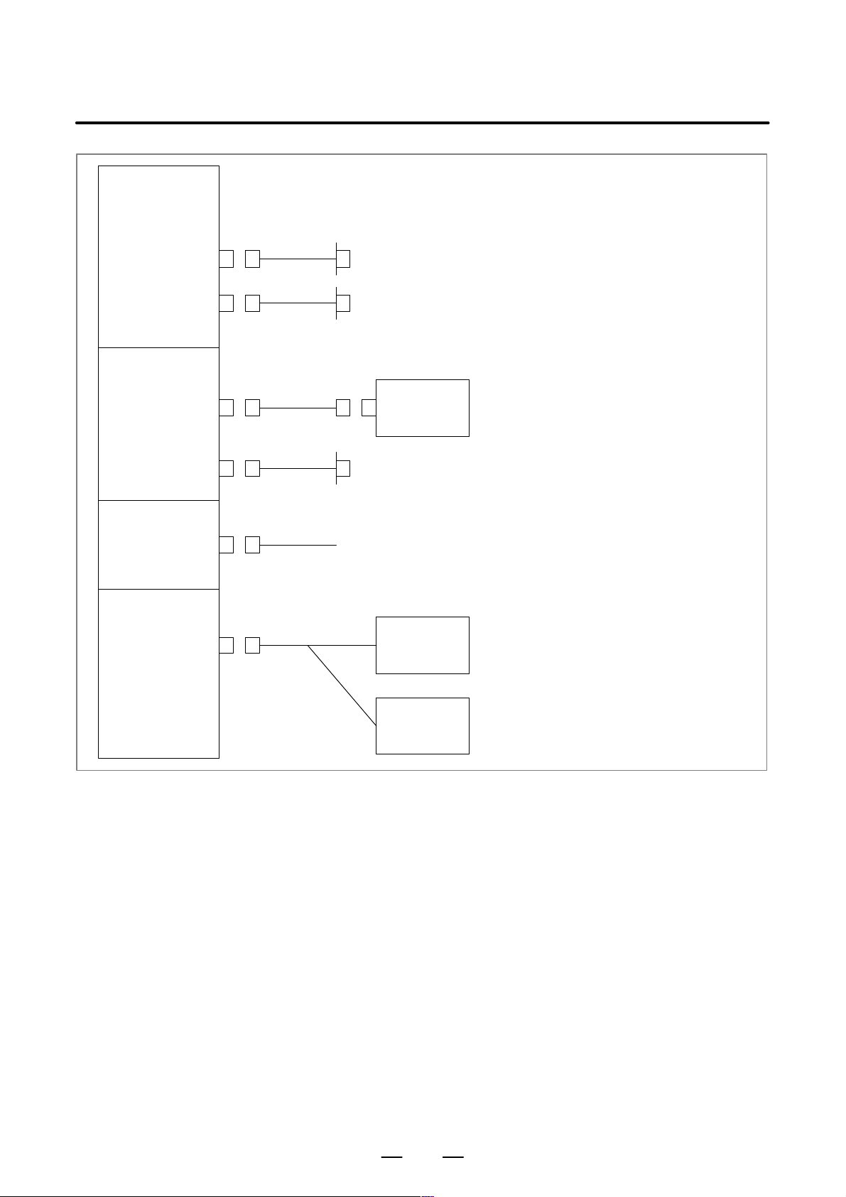
2. CONFIGURATIONHARDWARE
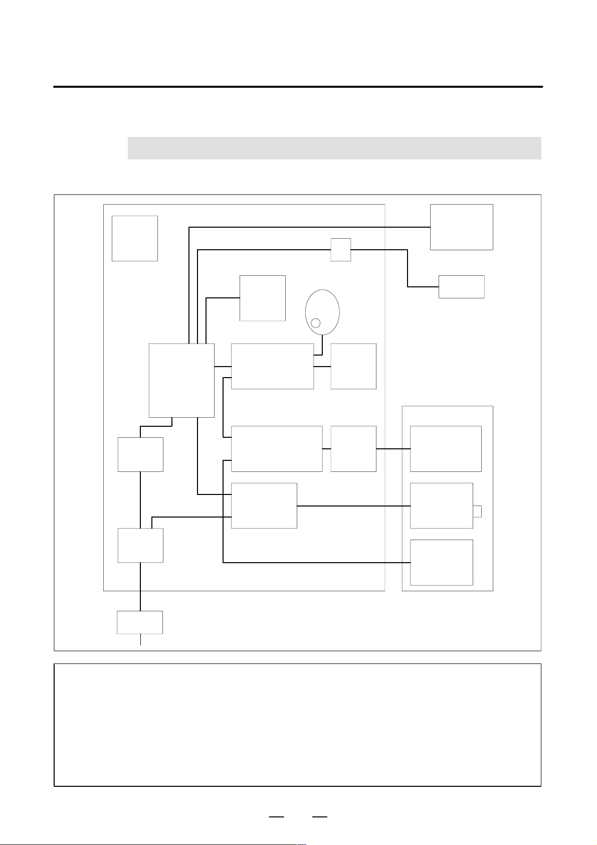
CONFIGURATION
Heat
exchanger
(3.7)
24 VDC
power
supply
Control unit
(3.9)
(7.3 to 7.6)
Relay connector (7.2)
Manual pulse generator
MDI unit
(7.1)
Operator’s panel
I/O module etc.
(6.4, 6.5, 6.7)
Connector panel I/O
module, I/O unit, etc.(*1)
(6.3, 6.6)
Servo amplifier
(7.9)
(6.3.6)
Machine
operator’s
panel
Power
magnetic
circuit
(*2)
Host computer
I/O device
Sensor/actuator
Servo motor
Multi–tap
transformer
Laser oscillator
Power supply
Distribution
board
NOTE
1 For information about the I/O unit, refer to the “FANUC I/O Unit Model A
Connection/Maintenance Manual (B–61813E)” and “FANUC I/O Unit Model B Connection
Manual (B–62163E).”
2 For an explanation of the connection between the amplifier and motor, refer to the following
manuals:
D FANUC AC Servo Motor α series Descriptions (B–65142E)
D FANUC Servo Amplifier α series Descriptions (B–65162E)
5

3. CONTROL UNIT
CONTROL UNIT
3
HARDWARE
B–63193EN/02
6
B–63193EN/02
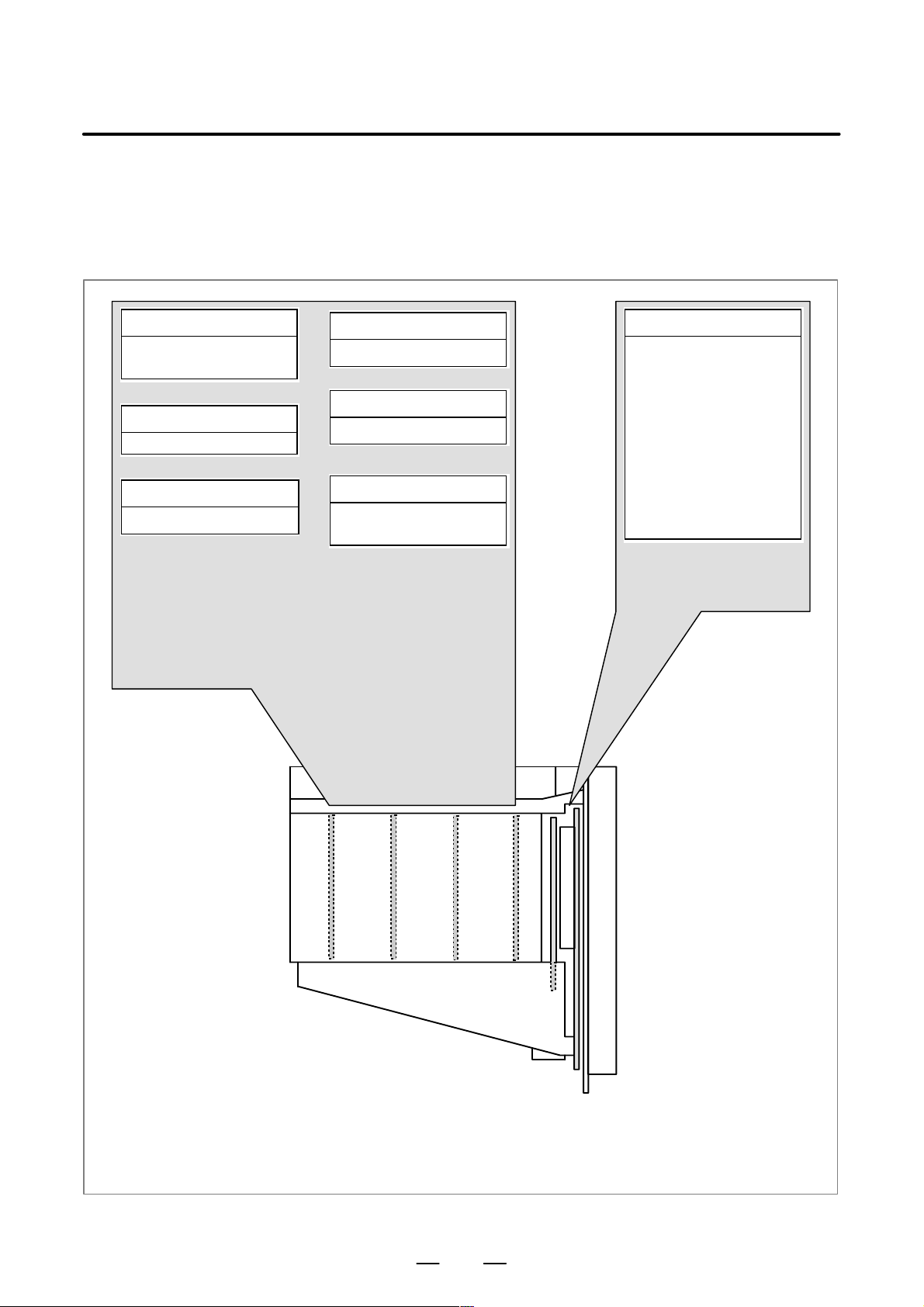
3.1
CONFIGURATION OF THE CONTROL UNIT
3. CONTROL UNITHARDWARE
Serial communication board
Remote buffer/
DNC1/DNC2/HDLC
C board
C functions for PMC
Analog input board
Tracing function
Data server board
Data server function
RISC board
High–precision contour control
function
HSSB interface board
High–speed serial bus
interface (for Series 160i only)
Options
Mother board
CPU for controlling CNC
· Power supply
· 2–axis to 8–axis control
· Spindle interface
· LCD/MDI
· I/O link
· PMC–SB6
· Analog output/high–
speed DI
· RS–232C × 2
· Memory card interface
· PC functions
(for Series 160i
with PC functions)
Basic system
The following types of units are
available:
D Unit without option slots
D Unit having two option slots
D Unit having four option slots
On a unit with option slots, as many option boards as the number of option slots can be mounted. (On a unit
having four option slots, only a data server board or HSSB interface board can fit into the slot furthest from the
LCD. On a unit having three option slots, only one of the above mentioned boards can fit into the center slot.)
7
4. TOTAL CONNECTION DIAGRAM
TOTAL CONNECTION DIAGRAM
4
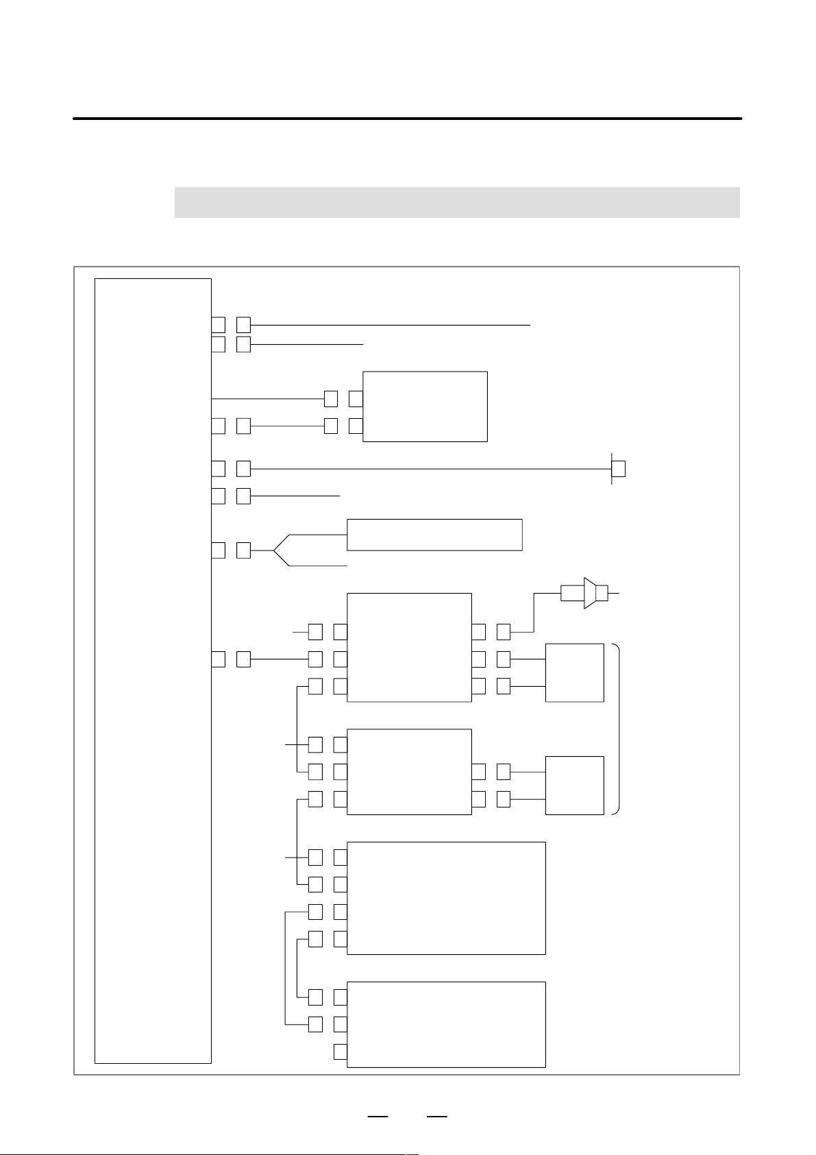
Mother board (1/2)
(with LCD)
24V–IN (CP1A)
24V–OUT (CP1B)
HARDWARE
To I/O device etc.
B–63193EN/02
24 VDC power
MDI (CA55)
R232–1 (JD36A)
R232–2 (JD36B)
A–OUT&HDI (JA40)
I/O LINK (JD1A)
Soft key cable
24 VDC
24 VDC
MDI UNIT
CK2
CK1
RS–232C
I/O device
Touch panel or RS–232C I/O device
(When the unit has PC functions, the touch panel is connected to JD33.)
Assist gas pressure analog output
High–speed skip input
Distributed
CP1A
JD1B
JD1A
CP1A
JD1B
JD1A
I/O board
JA3
Distributed
I/O board,
I/O unit, etc.
Manual pulse generator
Operator’s
panel
Up to 13 distributed
I/O units can be
connected.
Power
magnetics
cabinet
24 VDC
CP1A
JD1B
JD1A
(200 VAC)
(200 VAC)
JD1B
JD1A
Laser oscillator
Laser gas mixer
8
B–63193EN/02
4. TOTAL CONNECTION DIAGRAMHARDWARE
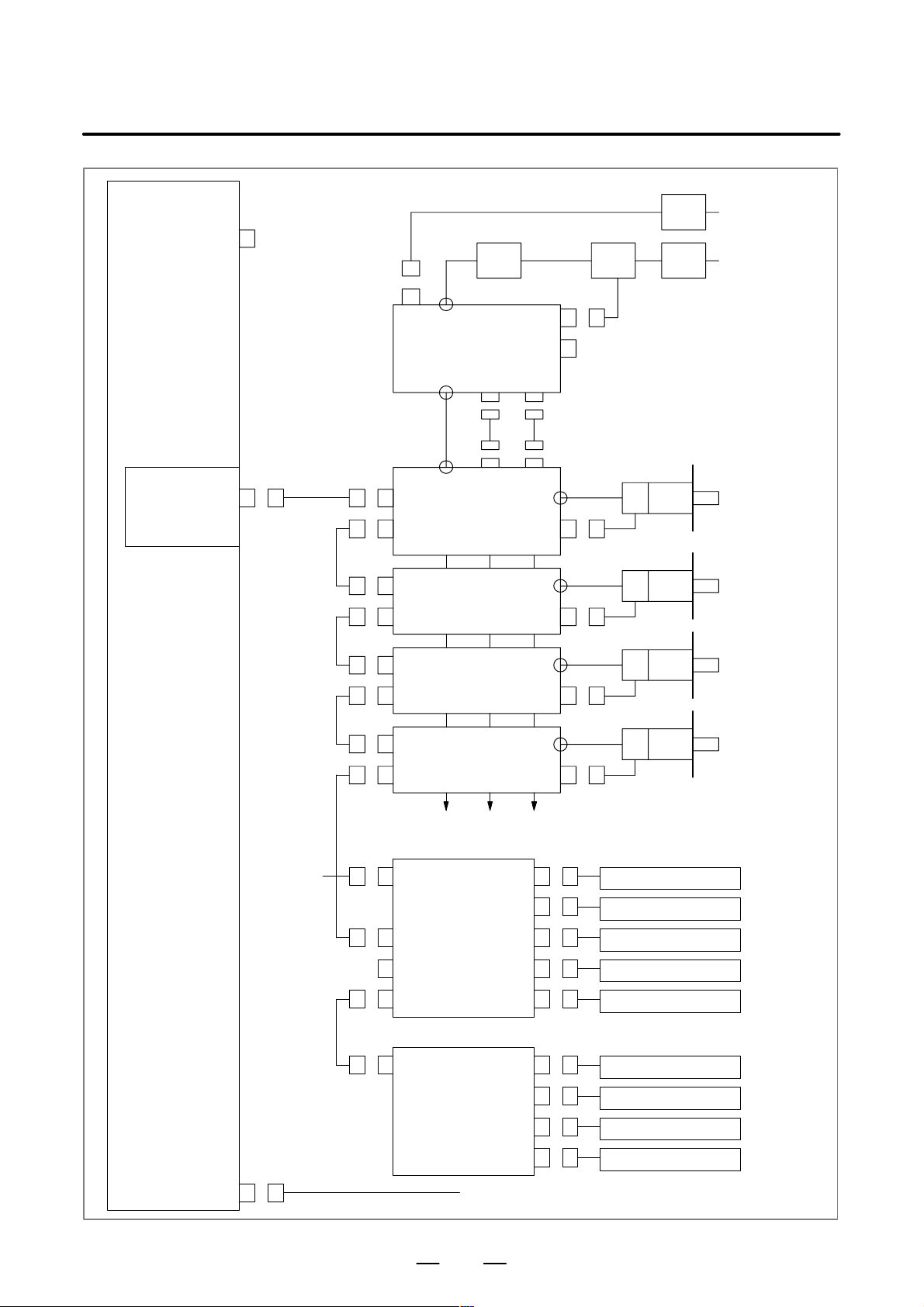
Mother board (2/2)
SPDL&POS (JA41)
Servo card
FSSB
(COP10A) TB2COP10B
CX1A TB2
PSM
CX1B
TB1
TB2 CX2A JX1A
TB1 CX2B JX1B
COP10B
COP10A
AC reactor
CX3
CX4
CX2B JX1B
SVM
JF1COP10A
SVM
Breaker
200 VAC
200 VAC
MCC breaker
Axis 1 servo
motor
Axis 2 servo
motor
COP10B
COP10A
COP10B
COP10A
Up to six or eight axes, depending on the model
Separate detector interface unit 1
24 VDC CP1 1A
COP10B
COP10A
CNF1
Separate detector interface unit 2
CNF2 JF105
SVM
SVM
JF101
JF102
JF103
JF104
JA4A
JF106
Axis 3 servo
motor
Axis 4 servo
motor
Linear scale, axis 1
Linear scale, axis 2
Linear scale, axis 3
Linear scale, axis 4
Absolute scale battery
Linear scale, axis 5
Linear scale, axis 6
SV–CHK (CA54)
JF107
JF108
Servo check
9
Linear scale, axis 7
Linear scale, axis 8
4. TOTAL CONNECTION DIAGRAM
Serial communication
board
Remote buffer board
DNC1 board
DNC2 board
R232–3 (JD28A)
R422–1 (JD6A)
Data server board
HARDWARE
RS–232C I/O device
(when the remote buffer board or DNC2 board is used)
RS–422 I/O device
(when the remote buffer board or DNC1 board is used)
B–63193EN/02
HDD (CNH1)
10BASE5 (CD27)
HSSB board
HSSB (COP7)
Analog option board
A–IN & A–OUT (JA6)
Hard disk unit
Ethernet
Personal Computer
Tracing sensor
Assist gas
pressure
analog output
The hard disk unit is mounted in the rear of the MDI unit.
The cable for the hard disk unit is provided by FANUC.
10

B–63193EN/02
5
5. POWER SUPPLYHARDWARE
POWER SUPPLY
11
5. POWER SUPPLY
HARDWARE
B–63193EN/02
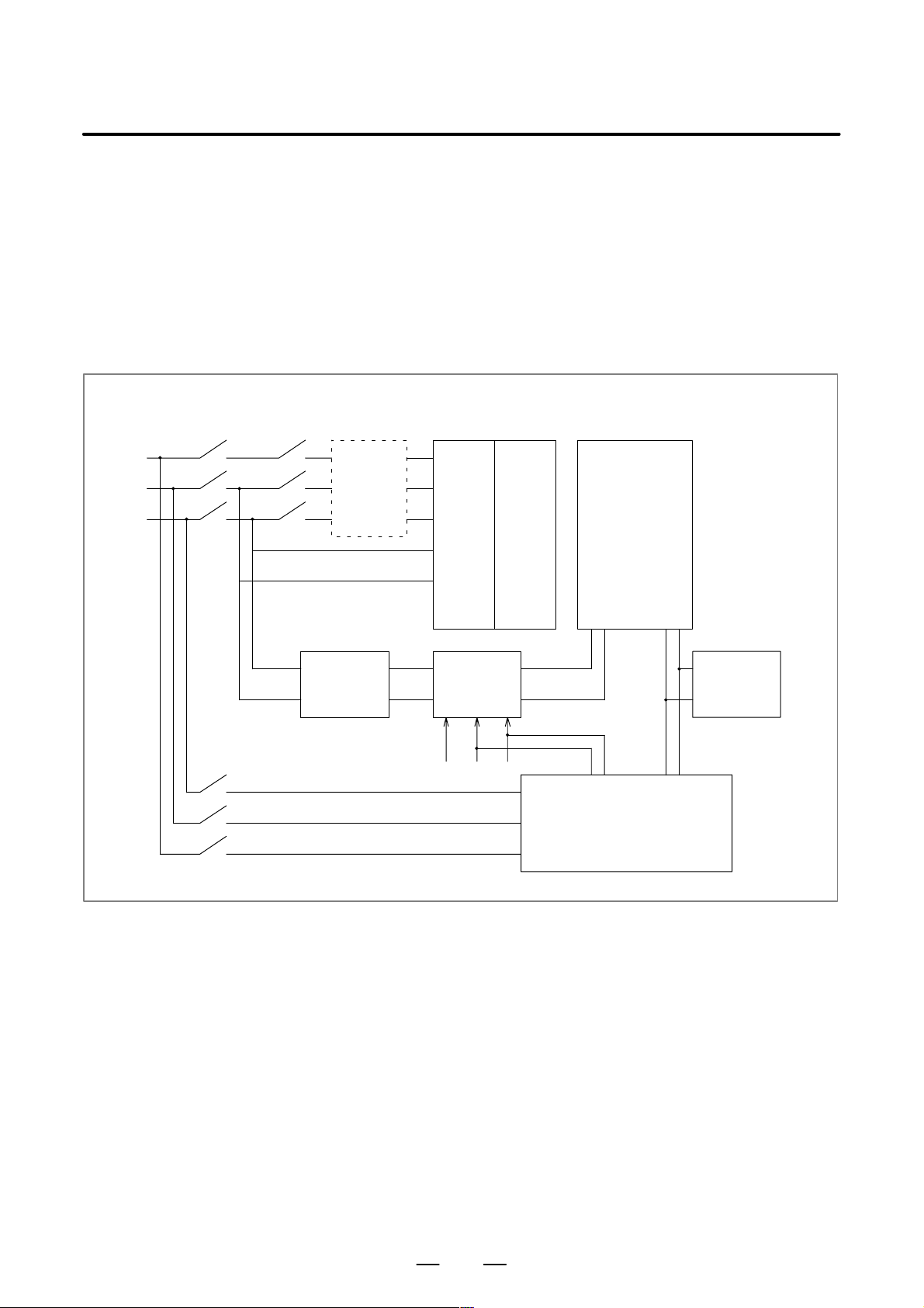
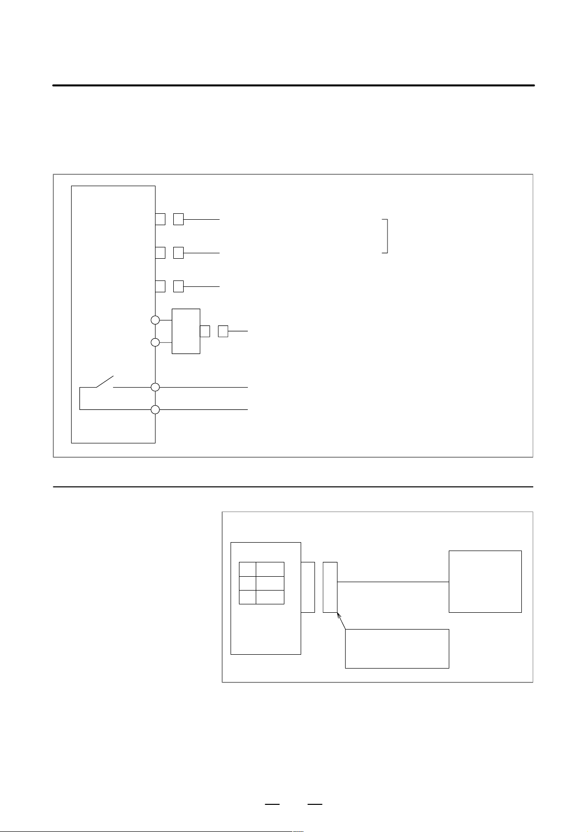
5.1
CONTROL UNIT POWER SUPPLY
Main breaker
Magnetic
contactor
Supply power (24 VDC) from an external source to the control unit of the
Series 16i–LA/160i–LA system. Install an external power–on/off switch
for the control unit, as shown in the figure below. When the Series
160i–LA system with PC functions is used, apply countermeasures to
guard against possible destruction of the data on the hard disk due to a
momentary power failure; for example, install an uninterruptible power
supply. The power rating is equal to the sum of the capacity of the control
unit (total power consumption in the unit indicated in Section 3.6 plus a
margin of about 20% to 30%) and the output via the control unit (output
from CP1B).
AC line filter
Servo
converter
3–phase
200 VAC
for power
line
Single–
phase
200 VAC
for control
line
Servo
inverter
Control unit
24 VDC
input
24 VDC
output
External
24 VDC
source
On/off circuit
ON COM OFF
3–phase
200 VAC
for power
line
Power–off
interlock
signals
OF1 1 and
OF12
I/O unit etc.
Start signal
(about 25 mA)
Laser oscillator
12
B–63193EN/02
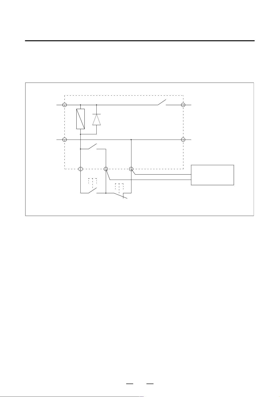
5. POWER SUPPLYHARDWARE
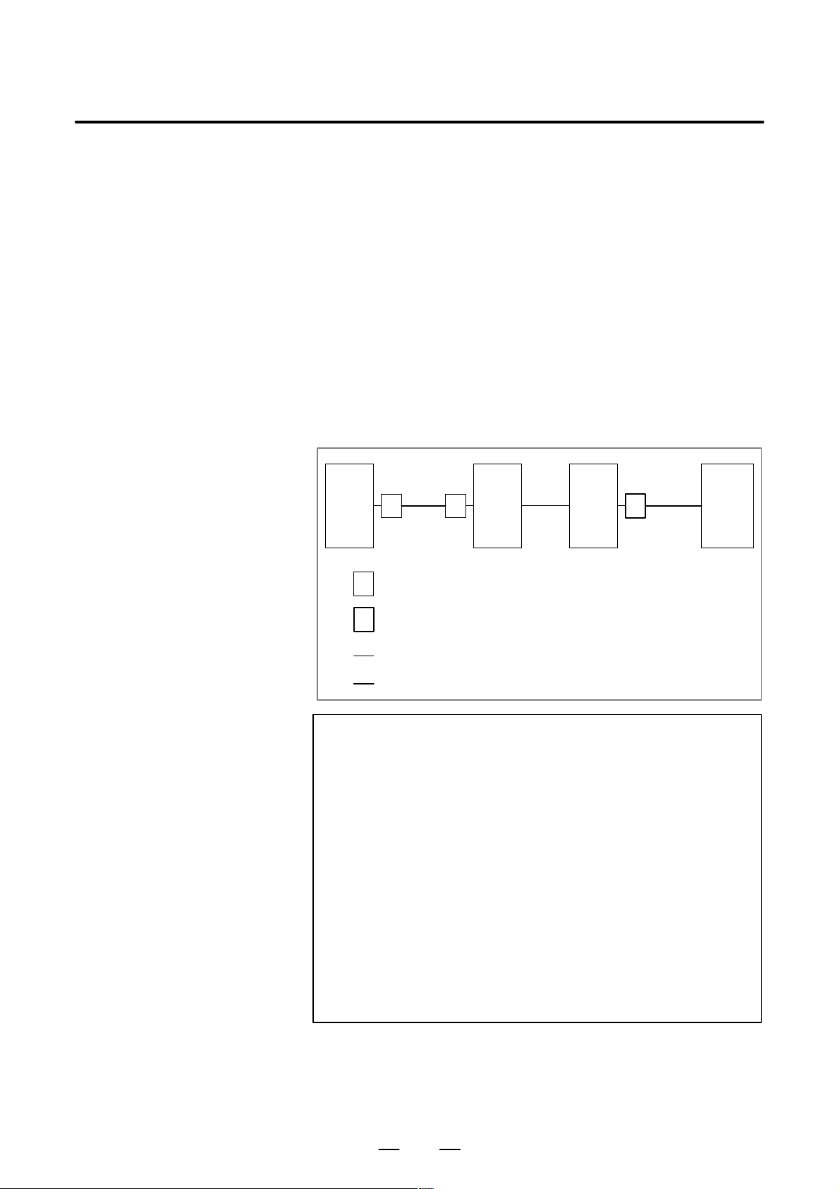
Sample on/off circuit
The figure below shows a sample on/off circuit. Select the circuit devices
according to the actual power rating. Connect the OFF and COM lines
to the OF11 and OF12 contacts of the laser oscillator , respectively , so that
an interlock can be applied to the power–off switch.
+24V +24V
RY1
24 VDC
input
0V 0V
ry1
ON COM OFF
On button Off button
ry1
24 VDC output
The power rating is equal to
the sum of the capacity of
the CNC control unit and
the output from CP1B.
On/off circuit
OF11
OF12
Laser oscillator
Power–off
interlock signal
13
6. I/O LIMITATION BASED ON LASER
OSCILLATOR CONNECTION
I/O LIMITA TION BASED ON LASER OSCILLATOR CONNECTION
6
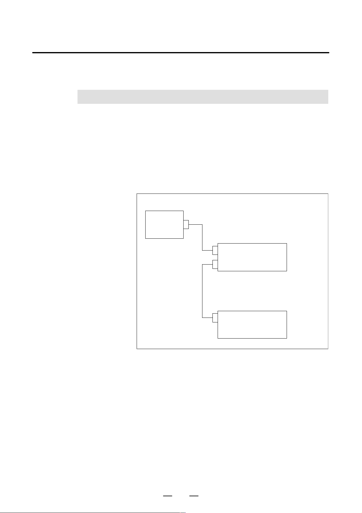
In the FS16i–LA system, the laser oscillator is connected in series via the
I/O unit.
For a laser oscillator interface, three groups with 256 DI and 256 DO
points are reserved.
The machine can therefore use up to 13 groups with 768 DI and 768 DO
points (X0 to X95 and Y0 to Y95).
Areas X96 to X127 and Y96 to Y127 cannot be used, even when a ladder
is used to specify writing to these areas.
HARDWARE
FS16i–LA
B–63193EN/02
Mother board
Up to 13 groups with 768 DI and
768 DO points
I/O board etc.
(Note) Areas X96 to X127 and
Y96 to Y127 cannot be
used with a ladder.
Three groups with 256 DI and 256
DO points (reserved by the CNC)
Laser oscillator
[User area]
X0 to X95
Y0 to Y95
14

B–63193EN/02
7
7. LASER OSCILLATORHARDWARE
LASER OSCILLATOR
15
7. LASER OSCILLATOR
7.1
CONNECTION OF THE LASER OSCILLATOR
Laser oscillator
HARDWARE
B–63193EN/02
JD1B
COP1
JD1A
ON
OFF
OF11
OF12
7.1.1
Connection of the
Adaptor
CP1A
Adaptor
I/O Link (when a metal cable is used)
Connected to the last I/O unit
I/O Link (when an optical fiber cable is used)
I/O Link Connected to the laser gas mixer
Oscillator on/off signal
(24 VDC, about 25 mA)
Power–of f interlock signal Connected to the external
Adaptor
Connected to CP1B of the CNC
power–on/off circuit
External source
CP1A
1 +24V
20V
3
24 VDC stabilized
power supply
24 VDC "10%
25 mA
AMP Japan, Ltd.
2–178288–3 (housing)
1–175218–5 (contact)
16
B–63193EN/02
7. LASER OSCILLATORHARDWARE
7.2
LASER OSCILLA T OR CONNECTION USING AN OPTICAL FIBER CABLE
When one of the following conditions is satisfied, an optical fiber cable
must be used to connect the laser oscillator to the I/O link:
(1)The length of the required cable is at least 10 m.
2
(2) A 5.5–mm
grounding line cannot be used to establish a connection
between the CNC control unit and the cabinet housing the I/O unit etc.,
or a connection between the CNC control unit and the laser oscillator.
(3)The cable may be susceptible to high–level noise.
For example, when the cable is placed near any machine which
produces high–level magnetic noise, such as a welder . Or , when most
of the cable runs parallel to a power line or power magnetics cable.
(4) The laser oscillator to be connected is certified by the CE marking
system.
Optical I/O link adaptors
To use optical fiber cables for making connections, optical I/O link
adaptors must be used, as shown below.
CNC I/O
UNIT
I/O
UNIT
Laser
oscillator
Adaptor: Standard or high–speed type (Each optical fiber cable must
be connected between the same type of adaptors.)
Adaptor: Standard type
Electrical cable
Optical fiber cable
NOTE
1 T o daisy–chain I/O units to a single I/O link, both optical fiber
cables and electrical cables can be used.
2 When an optical fiber cable is used, an optical I/O link
adaptor must also be used.
3 Two types of optical I/O link adaptors are supported:
Standard and high–speed.
4 When four or more optical fiber cables are used (that is,
when four or more connections are established), the cables
should be of high–speed type.
5 Each laser oscillator contains a standard type adaptor. To
establish a connection to the laser oscillator, therefore, an
I/O unit must be provided with a standard type I/O link
adaptor, because only adaptors of the same type can be
connected to each other.
For an explanation of FANUC I/O link connection using electrical cables,
or the outside dimensions of optical I/O link adaptors, refer to Section 6.2,
“FANUC I/O Link Connection,” in the “Series 16i–MODEL A
Connection Manual.”
17
7. LASER OSCILLATOR
HARDWARE
B–63193EN/02
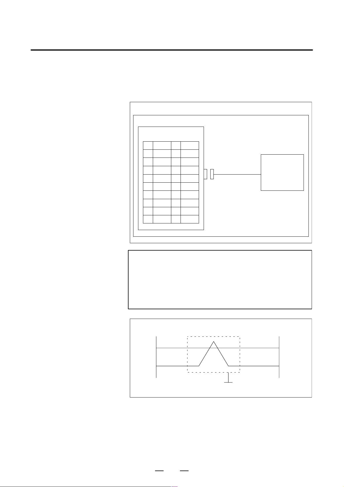
7.3
ASSIST GAS PRESSURE ANALOG OUTPUT
Assist gas pressure analog output signals are output from either the analog
spindle interface on the main board or the analog output interface on the
analog option board.
Which interface to use can be specified with the appropriate parameter.
For details, see ”ASSIST GAS CONTROL” in ”LASER FUNCTION.”
To output signals from the main board
CNC
JA40
PCR–E20MD
1 (HDI0)
20V
3 (HDI2)
40V
5ES
6 (HDI4)
7 SVC 17 (HDI6)
8 ENB1
9 ENB2
10 0V
11 (HDI1)
12 0V
13 (HDI3)
14 0V
15 (HDI5)
16 0V
18 0V
19 (HDI7)
20 0V
Assist gas
control unit
CAUTION
1 SVC, ES: Common lines are used for the SVC, ES, and
assist gas pressure analog output signals.
2 The signals in parentheses are high–speed DI input signals.
3 For details of the output voltage, see the section on assist
gas control in the function description.
Cable connection
JA40
7
SVC
5
ES
Shield
Output voltage range: 0 to 10 V
Ground
Assist gas
control unit
18

B–63193EN/02
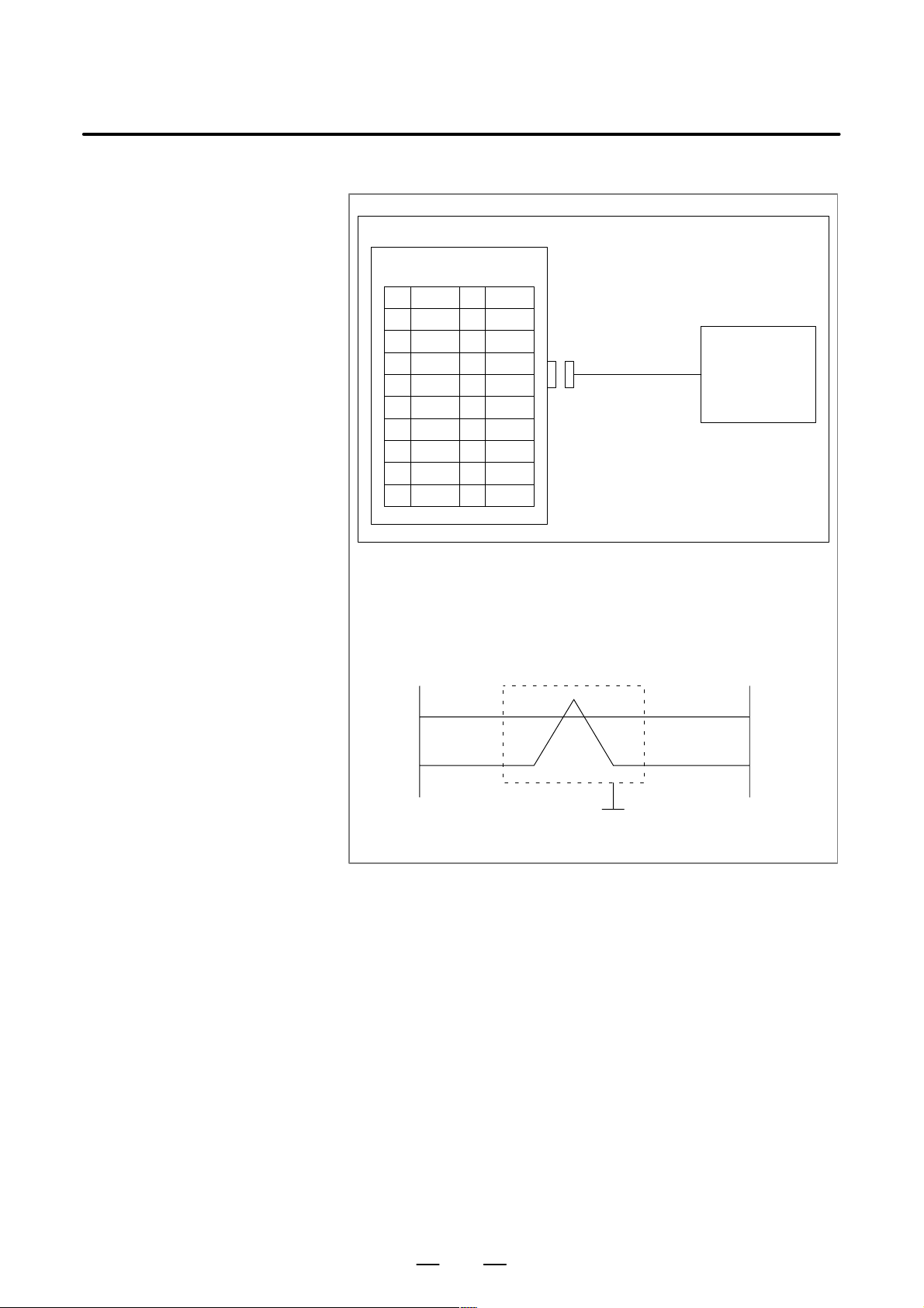
To output signals from the analog option board
CNC
JA6
PCR–E20MD
1 AIN0
20V
3 (AIN2)
4 (0V)
5 AOUT
60V
7 17
8
9
10
11 (AIN1)
12 (0V)
13 (AIN3)
14 (0V)
15
16 (0V)
18
19
20
7. LASER OSCILLATORHARDWARE
Assist gas
control unit
CAUTION
1 AOUT, 0V: Common lines are used for the AOUT, 0V, and
assist gas pressure analog output signals.
2 The signals in parentheses cannot be used.
3 For details of the output voltage, see the section on assist
gas control in the function description.
Cable connection
JA6
5
AOUT
6
0V
Shield
Input voltage range: 0 to 10 V
Ground
Assist gas
control unit
19
7. LASER OSCILLATOR
7.4
CONNECTION OF THE TRACING SENSOR
HARDWARE
CNC
JA6
PCR–E20MD
1 AIN0
20V
3 (AIN2)
4 (0V)
5 (AOUT)
6 (0V)
7 17
8
9
10
Note 1) AIN0, 0V: Common lines are used for the AIN0, 0V, and analog input
Note 2) The signals in parentheses cannot be used.
Note 3) For details of the input voltage, see the section on tracing control in
11 (AIN1)
12 (0V)
13 (AIN3)
14 (0V)
15
16 (0V)
18
19
20
signals.
the function description.
B–63193EN/02
Tracing sensor
Cable connection
JA6
1
AIN0
2
0V
Shield
Input voltage range: –10 to +10 V
Tracing
sensor
Ground
20

II. LASER FUNCTION

B–63193EN/02
1
1. FUNCTIONSLASER FUNCTION
FUNCTIONS
Overview
Functions
For information about connections other than the laser functions, refer to
the “16i/18i/21i/20i/160i/180i/210i–MODEL A Connection Manual:
Function” (B–63003EN–1).
Most of the functions described in manual (B–63003EN–1) can be used
with the 16i–LA. Note, however , that some functions cannot be used with
the 16i–LA, while others require a different specification for use with the
16i–LA.
Whether the functions described in manual (B–63003EN–1) can be used
with the 16i–LA is listed below.
For details of those functions for which a different specification is
necessary, see Chapter 2. The functions are listed below.
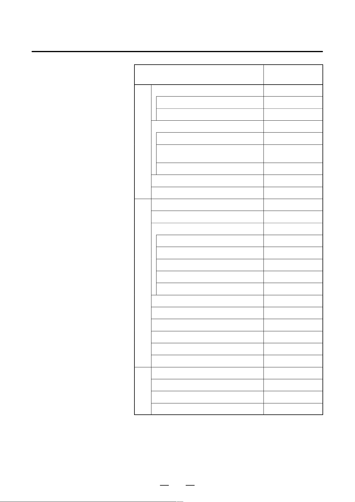
The meanings of the symbols used in the table are as follows:
f : Usable with the 16i–LA
: Not usable with the 16i–LA
∆ : The specifications differ slightly.
Item Usable/not usable
with the 16i–LA
1
Controlled axis f
Each axis setting
Axis name f
Increment system f
Rotation axis specification f
Control axis detach f
Axis movement status output f
Mirror image f
Follow–up f
Servo off (mechanical handle feed) f
Position switch f
Error compensation
Stored pitch error compensation f
Backlash compensation f
23
1. FUNCTIONS LASER FUNCTION
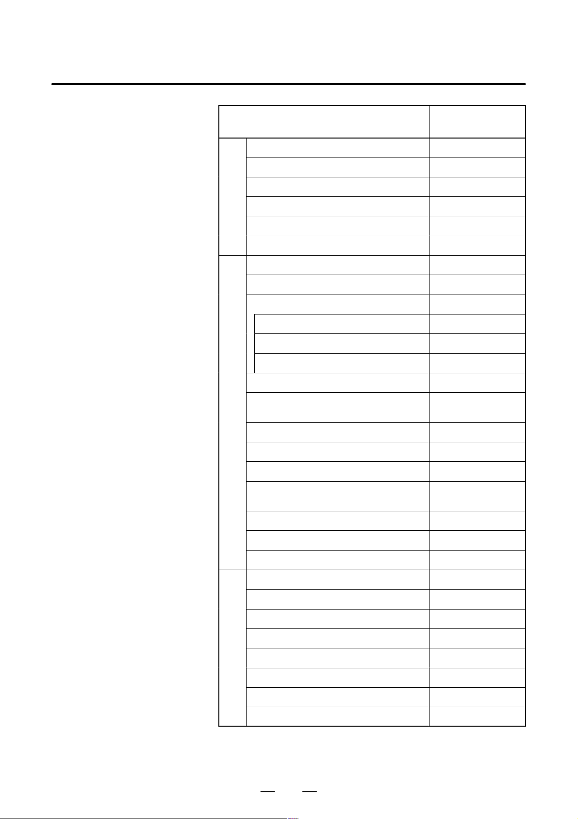
Item Usable/not usable
1
Settings related to servo control axis
Servo parameters f
Absolute position detection f
Settings related to coordinate system
Machine coordinate system f
B–63193EN/02
with the 16i–LA
Workpiece coordinate system/Addition of
workpiece coordinate system pair
Rotary axis roll over f
Simple synchronous control f
Tandem control f
2
Emergency stop ∆ : Refer to chapter2
Ready signal f
Overtravel check
Overtravel signal f
Stored stroke limit 1 f
Stored stroke limit 2, 3 f
Chuck & tail stock barrier (T series)
Tool post interference check (T series)
Alarm signal f
Start lock/Inter lock f
f
Mode selection f
Tool post selection (T series)
Status output signal f
VRDY OFF alarm ignore signal f
3
Manual continuous feed/Incremental feed f
Manual handle feed f
Handle interruption f
Tool direction handle feed (M series)
24
B–63193EN/02
1. FUNCTIONSLASER FUNCTION
Item Usable/not usable
with the 16i–LA
4
Manual reference position return f
Reference position setting without DOG f
Reference position shift f
Reference position return f
2nd/3rd/4th reference position return f
Floating reference position return f
5
Cycle start/Feed hold ∆ : Refer to chapter2
Reset/Rewind f
Test operation
Machine lock ∆ : Refer to chapter2
Dry run ∆ : Refer to chapter2
Single block ∆ : Refer to chapter2
Manual absolute on/off f
Optional block skip/Optional block skip
addittion
Sequence number comparison and stop f
Program restart ∆
Tool retract & recover (M series)
Exact stop/Exact stop mode/Tapping mode/
Cutting mode
Balanced cutting (T series)
DNC operation f
Manual intervention and return f
6
Positioning f
Linear interpolation f
Circular interpolation f
Thread cutting
∆ : Tapping mode is
not usable.
f
Single direction positioning f
Helical interpolation f
Involute interpolation
Polar coordinate interpolation f
25
Loading...