


 Loading...
SERVICE MANUAL
Color Inkjet Printer
Epson WF-7525 / Epson WF-7521 / Epson WF-7520/
Epson WF-7515 / Epson WF-7511 / Epson WF-7510/
Epson WF-7018 / Epson WF-7015 / Epson WF-7012/
Epson WF-7011 / Epson WF-7010
SEMF10-012
Notice:
All rights reserved. No part of this manual may be reproduced, stored in a retrieval system, or transmitted in any form or by any means, electronic, mechanical, photocopying, recording, or otherwise, without the prior written permission of SEIKO EPSON CORPORATION.
All effort have been made to ensure the accuracy of the contents of this manual. However, should any errors be detected, SEIKO EPSON would greatly appreciate being informed of them.
The contents of this manual are subject to change without notice.
The above not withstanding SEIKO EPSON CORPORATION can assume no responsibility for any errors in this manual or the consequences thereof.
EPSON is a registered trademark of SEIKO EPSON CORPORATION.
Note :Other product names used herein are for identification purpose only and may be trademarks or registered trademarks of their respective owners. EPSON disclaims any and all rights in those marks.
Copyright 2011 SEIKO EPSON CORPORATION
I&I CS Quality Assurance Department

Safety Precautions
All safety procedures described here shall be strictly adhered to by all parties servicing and maintaining this product.
DANGER
Strictly observe the following cautions. Failure to comply could result in serious bodily injury or loss of life.
1.Always disconnect the product from the power source and peripheral devices when servicing the product or performing maintenance.
2.When performing works described in this manual, do not connect to a power source until instructed to do so. Connecting to a power source causes high voltage in the power supply unit and some electronic components even if the product power switch is off. If you need to perform the work with the power cable connected to a power source, use extreme caution to avoid electrical shock.
WARNING
Strictly observe the following cautions. Failure to comply may lead to personal injury or loss of life.
1.Always wear protective goggles for disassembly and reassembly to protect your eyes from ink in working. If any ink gets in your eyes, wash your eyes with clean water and consult a doctor immediately.
2.When using compressed air products; such as air duster, for cleaning during repair and maintenance, the use of such products containing flammable gas is prohibited.
PRECAUTIONS
Strictly observe the following cautions. Failure to comply may lead to personal injury or damage of the product.
1.Repairs on Epson product should be performed only by an Epson certified repair technician.
2.No work should be performed on this product by persons unfamiliar with basic safety knowledge required for electrician.
3.The power rating of this product is indicated on the serial number/rating plate. Never connect this product to the power source whose voltages is different from the rated voltage.
4.Replace malfunctioning components only with those components provided or approved by Epson; introduction of second-source ICs or other non-approved components may damage the product and void any applicable Epson warranty.
5.The capacitors on the Main Board may be electrically charged right after the power turns off or after driving motors which generates counter electromotive force such as when rotating the PF Roller or when moving the CR Unit. There is a risk to damage the Main Board if the Head FFC is short-circuited with the capacitors on the Main Board electrically charged, therefore, after the power turns off or after motors are driven, leave the printer untouched for approximately 30 seconds to discharge the capacitors before starting disassembly/ reassembly.
6.To prevent the circuit boards from short-circuiting, be careful about the following when handling FFC or cables.
When handling FFC, take care not to let the terminal section of FFC touch metal parts.
When connecting cables/FFC to the connectors on circuit boards, connect them straight to the connectors to avoid slant insertion.
7.In order to protect sensitive microprocessors and circuitry, use static discharge equipment, such as anti-static wrist straps, when accessing internal components.
8.Do not tilt this product immediately after initial ink charge, especially after performing the ink charge several times. Doing so may cause ink to leak from the product because it may take some time for the waste ink pads to completely absorb ink wasted due to the ink charge.
9.Never touch the ink or wasted ink with bare hands. If ink comes into contact with your skin, wash it off with soap and water immediately. If you have a skin irritation, consult a doctor immediately.
10.When disassembling or assembling this product, make sure to wear gloves to avoid injuries from metal parts with sharp edges.
11.Use only recommended tools for disassembling, assembling or adjusting the printer.
12.Observe the specified torque when tightening screws.
13.Be extremely careful not to scratch or contaminate the following parts.
Nozzle plate of the printhead
CR Scale
PF Scale
Coated surface of the PF Roller
Gears
Rollers
LCD
Scanner Sensor
Exterior parts
14.Never use oil or grease other than those specified in this manual. Use of different types of oil or grease may damage the component or give bad influence on the printer function.
15.Apply the specified amount of grease described in this manual.
16.Make the specified adjustments when you disassemble the printer.
17.When cleaning this product, follow the procedure described in this manual.
18.When transporting this product after filling the ink in the printhead, pack the printer without removing the ink cartridges in order to prevent the printhead from drying out.
19.Make sure to install antivirus software in the computers used for the service support activities.
20.Keep the virus pattern file of antivirus software up-to-date.
21.When disassembling/reassembling this product, if you find adhesive power of the double-sided tape which secure the parts or FFC is not enough, replace the tape with new one and attach it correctly to the specified points where the parts or FFC should be secured.
22.Unless otherwise specified in this manual, the labels attached on the returned product should be transferred to the corresponding attachment positions on the new one referring to the labels on the returned product.

About This Manual
This manual, consists of the following chapters, is intended for repair service personnel and includes information necessary for properly performing maintenance and servicing the product.
CHAPTER 1. PRODUCT DESCRIPTIONS
Provides a general overview and specifications of the product.
CHAPTER 2. OPERATING PRINCIPLES
Describes the theory of mechanical operations of the product.
CHAPTER 3. TROUBLESHOOTING
Describes the step-by-step procedures for the troubleshooting.
CHAPTER 4. DISASSEMBLY / REASSEMBLY
Describes the disassembly/reassembly procedures for main parts/units of the product.
CHAPTER 5. ADJUSTMENT
Describes the required adjustments for servicing the product.
CHAPTER 6. MAINTENANCE
Describes maintenance items and procedures for servicing the product.
Symbols Used in this Manual
Various symbols are used throughout this manual either to provide additional information on a specific topic or to warn of possible danger present during a procedure or an action. Pay attention to all symbols when they are used, and always read explanation thoroughly and follow the instructions.
Indicates an operating or maintenance procedure, practice or condition that, if not strictly observed, could result in serious injury or loss of life.
Indicates an operating or maintenance procedure, practice, or condition that, if not strictly observed, could result in bodily injury, damage or malfunction of equipment.
May indicate an operating or maintenance procedure, practice or condition that is necessary to accomplish a task efficiently. It may also provide additional information that is related to a specific subject, or comment on the results achieved through a previous action.
For Chapter 4 “Disassembly/Reassembly”, symbols other than indicated above are used to show additional information for disassembly/reassembly. For the details on those symbols, see "4.2 Disassembly/Reassembly Procedures (p46)".

Revision Status
Revision |
Date of Issue |
Description |
A |
Aug. 24, 2011 |
First Release |

Epson WF-7520/7510/7010 series |
Revision A |
Contents
Chapter 1 Product description
1.1 |
Features . |
................................................................................................................................................................... |
10 |
|
1.2 |
Printing Specifications . ............................................................................................................................................ |
12 |
||
|
1.2.1 |
Basic . ........................................................................................................................................Specifications |
12 |
|
1.3 |
Scanner Specifications ...............................................................................................(WF-7520/7510 series only) |
13 |
||
|
1.3.1 |
Basic . ........................................................................................................................................Specifications |
13 |
|
1.4 |
Control Panel. ........................................................................................................................................................... |
14 |
||
|
1.4.1 |
Operation . ...........................................................................................................................................Buttons |
14 |
|
|
1.4.2 LEDs .............................................................................................................................and LCD Indications |
16 |
||
1.5 |
Various Settings . ...................................................................................................................................................... |
19 |
||
|
1.5.1 |
Panel . ..............................................................................................................................................Operation |
19 |
|
|
1.5.1.1 ....................................................................... |
Setup Menu Configuration (WF - 7520/7510 series only) |
19 |
|
|
1.5.1.2 .............................................................................................Forced Power OFF (WF-7010 series only) |
20 |
||
|
1.5.1.3 . ................................................................................................................................ |
Printer Status Sheet |
20 |
|
Chapter 2 Operating Principles |
|
|||
2.1 |
Overview . ................................................................................................................................................................. |
|
22 |
|
2.2 |
Motors and . ................................................................................................................................................Sensors |
22 |
||
2.3 |
Optical Sensor . ............................................................................................................................................Control |
25 |
||
2.4 |
Power-On . ................................................................................................................................................Sequence |
26 |
||
Chapter 3 Troubleshooting |
|
|||
3.1 |
Troubleshooting. ....................................................................................................................................................... |
30 |
||
|
3.1.1 |
Error . ..........................................................................................................................................Message List |
30 |
|
|
3.1.2 Troubleshooting . ............................................................................................................................Workflow |
31 |
||
|
3.1.3 |
Fatal . .............................................................................................................................................Error Code |
33 |
|
|
3.1.4 FAX .......................................................................................Troubleshooting (WF-7520/7510 series only) |
37 |
||
|
3.1.4.1 . ................................................................................................................................................FAX Log |
37 |
||
|
3.1.4.2 ............................................................... |
Error Code/Superficial Phenomenon - Based Troubleshooting |
42 |
|
Chapter 4 Disassembly/Reassembly |
|
|||
4.1 |
Overview . ................................................................................................................................................................. |
|
45 |
|
|
4.1.1 |
Tools . ............................................................................................................................................................... |
45 |
|
|
4.1.2 |
Jigs . .................................................................................................................................................................. |
|
45 |
4.2 |
Disassembly/Reassembly ......................................................................................................................Procedures |
46 |
||
|
4.2.1 Parts/Units .................................................................................................Need to be Removed in Advance |
46 |
||
|
4.2.2 |
Disassembling ................................................................................................................................Flowchart |
48 |
|
|
4.2.2.1 . ......................................................................................................................................... |
Exterior Parts |
48 |
|
|
4.2.2.2 .................................................................................................................................. |
Printer Mechanism |
52 |
|
4.3 |
Detailed Disassembly/Reassembly ............................................................................Procedure for each Part/Unit |
55 |
||
4.4 |
Routing FFCs/cables . ............................................................................................................................................... |
63 |
||
4.5 |
Connector . ................................................................................................................................................Summary |
67 |
||
7

Epson WF-7520/7510/7010 series |
Revision A |
||
Chapter 5 Adjustment |
|
||
5.1 |
Required Adjustments . ............................................................................................................................................. |
69 |
|
5.2 |
Details of Adjustments . ............................................................................................................................................ |
75 |
|
|
5.2.1 PF Timing Belt Tension Check ....................................................................................................................... |
75 |
|
|
5.2.2 Checking the Platen Gap ................................................................................................................................. |
76 |
|
|
5.2.3 Scanner Timing Belt Tension Check............................................................................................................... |
77 |
|
|
5.2.4 MAC Address Setting. ..................................................................................................................................... |
78 |
|
Chapter 6 Maintenance |
|
||
6.1 |
Overview . ................................................................................................................................................................. |
80 |
|
|
6.1.1 |
Cleaning. .......................................................................................................................................................... |
80 |
|
6.1.2 |
Lubrication. ...................................................................................................................................................... |
80 |
6.2 |
Lubrication Points and Instructions.......................................................................................................................... |
81 |
|
8

CHAPTER 1
PRODUCT DESCRIPTION

Epson WF-7520/7510/7010 series |
Revision A |
1.1 Features
In this chapter, the product names are called as follows:
WF-7520 series: Epson WF-7525/Epson WF-7521/Epson WF-7520
WF-7510 series: Epson WF-7515/Epson WF-7511/Epson WF-7510
WF-7010 series: Epson WF-7018/Epson WF-7015/Epson WF-7012/Epson WF-7011/
Epson WF-7010
WF-7520/7510/7010 series are an A3 color inkjet printer based on Epson WorkForce 840/Epson Stylus Office BX925FWD. Major features are as follows.
Common futures
Printer
Maximum print speed: 15 ppm (A4, monochrome, draft printing mode)
O6-Chip Turbo 2 Printhead (Black: 128 nozzles x 3, Color: 128 nozzles x 1 per color)
Maximum print resolution: 5760 x 1440 dpi
Auto duplex printing up to A3 paper with the Duplex Unit (WF-7520/7010 series only)
Four independent ink cartridges are installed (pigment inks)
Interface
In addition to USB connection, wired/wireless LAN connection are available
Scanner (WF-7520/7510 series only)
CIS type sensor (scanning resolution: 1200 x 2400 dpi)
ADF up to A3 paper scanning*
Note"*": Auto duplex scanning is available only for WF-7520 series. (A4 or letter sized paper only)
Differences between the models
WF-7520/7510/7010 series are different as shown below.
Table 1-1. Differences between the Models
|
Item |
WF-7520 series |
WF-7510 series |
WF-7010 series |
|
LCD display size |
|
2.5 inch |
2.5 inch |
No |
|
Auto duplex printing |
|
Yes |
No |
Yes |
|
Scanner / ADF |
|
Yes |
Yes |
No |
|
USB host |
|
Yes |
Yes |
No |
|
(for PictBridge / Backup of an external storage device) |
|||||
|
|
|
|||
FAX |
|
Yes |
Yes |
No |
|
Wi-Fi |
|
Yes |
Yes |
Yes* |
|
2nd cassette |
|
Yes |
No |
Yes |
|
Note *: The availability of the WiFi varies depending on the destinations. |
|
|
|||
Available: |
EHC/Euro/CISMEA/ESP/ETT/EKL |
|
|
|
|
Not available: |
EAL/Latin/EAL/ECC/EHK |
|
|
|
|
Product description |
Features |
10 |
Epson WF-7520/7510/7010 series |
Revision A |
External view
WF-7520 series |
WF-7510 series |
WF-7010 series |
||
|
|
|
|
|
|
|
|
|
|
Figure 1-1. External View
Table 1-2. Dimensions
Model |
Dimensions (W x D x H)*1 |
Weight*2 |
WF-7520 series |
559 mm x 418 mm x 365 mm |
18.9 kg |
WF-7510 series |
559 mm x 418 mm x 287 mm |
15.6 kg |
WF-7010 series |
558 mm x 414 mm x 264 mm |
12.3 kg |
Note *1: Paper support for rear ASF and stacker are closed. Rubber feet are included. *2: Excluding the weight of ink cartridges and power cable.
Product description |
Features |
11 |

Epson WF-7520/7510/7010 series |
Revision A |
1.2 Printing Specifications
1.2.1 |
Basic Specifications |
|
|
|
|
|
Table 1-3. Printer Specifications |
||
|
Item |
|
|
Specification |
Print method |
On-demand ink jet |
|
||
Nozzle configuration |
Black: |
384 nozzles (128 nozzles x 3) |
||
|
|
Color: |
384 nozzles (128 nozzles x 1 per color) |
|
Color |
|
Black, Cyan, Magenta, Yellow |
||
Print direction |
Bi-directional minimum distance printing, Unidirectional printing |
|||
Print resolution |
Horizontal x Vertical (dpi) |
|||
|
|
• 360 x 120 |
• 720 x 720 |
|
|
|
• 360 x 360 |
• 1440 x 720 |
|
|
|
• 360 x 720 |
• 5760 x 1440 |
|
Control code |
• ESC/P Raster command |
|||
|
|
• ESC/P-R (RGB) command |
||
Input buffer size |
Printing from PC: |
64 KBytes |
||
|
|
Stand-alone printing: 132 KBytes |
||
Paper feed method |
Friction feed |
|
||
Paper feed amount |
250 pages (plain paper*), 20 pages (photo paper), 50 pages (postcard) |
|||
Paper path |
Front feed, front out |
|
||
PF interval |
0.01764 mm (1/1440 inch) |
|||
Note *: |
For paper thickness: 0.11 mm, 80 g/m2. |
|
|
|
Product description |
Printing Specifications |
12 |

Epson WF-7520/7510/7010 series |
Revision A |
1.3 Scanner Specifications (WF-7520/7510 series only)
1.3.1 Basic Specifications
|
Table 1-4. Basic Specifications |
Item |
Specification |
Scanner type |
Flatbed, color |
Scanning method |
Moving carriage, stationary document |
Home position |
The rear left corner |
Photoelectric device |
CIS |
Light source |
LED |
Maximum document sizes |
A3 or US B (tabloid) |
Scanning range |
11.7” x 17” (297 mm x 431.8 mm) |
Maximum resolution |
Main scan: 1,200 dpi |
|
Sub scan: 2,400 dpi |
Maximum effective pixels |
14,040 x 20,400 pixels |
Pixel depth |
16 bit per pixel (input) and 1 bit or 8 bit per pixel (output) |
|
Table 1-5. ADF Specifications |
Item |
Specification |
Document loading Maximum document sizes Supported paper type Paper thickness
Maximum number of documents which can be set Document path
Document set position Auto duplex scanning*
Face-up
A4 to A3/tabloid Plain paper only 64 to 95 g/m2
30 sheets or 3 mm at maximum
Feeds from upper tray and ejects to lower tray Center
A4 or US Letter only
Note *: WF-7520 series only
Product description |
Scanner Specifications (WF-7520/7510 series only) |
13 |

Epson WF-7520/7510/7010 series |
Revision A |
1.4 Control Panel
1.4.1 Operation Buttons
The operation buttons, LEDs, and LCD are shown below. See Table 1-6 and Table 1-7 for the functions. WF-7520/7510 series
Photo |
Copy |
Fax |
Scan |
|
Menu |
Back |
|
|
|
Start |
|
|
Stop |
Start |
 WF-7520 series only
Figure 1-2. Control Panel (WF-7520/7510 series)
Table 1-6. Operation Buttons, LEDs and LCD (WF-7520/7510 series)
Item Icon
LCD
Button/ touch panel
 -
- ,
, ,
,
Name |
Function |
|
|
Indicates the printer status, error, and menu screen. |
|
Power |
Turns the power on/off. |
|
Photo |
Enters photo mode. |
|
Display/Crop |
• Enters zoom setting screen for selected image. |
|
• Switches preview screens on LCD. |
||
|
||
Copy |
Enters copy mode. |
|
Reduce/Enlarge |
Specifies copy magnification. |
|
Quality |
Specifies print quality. |
|
2-Sided |
Specifies auto duplex print setting. (WF-7520 series only) |
|
Setup |
Enters setup mode. |
|
Help |
Displays help for solutions to problems. |
|
Reset |
Resets the current setting and displays the home screen. |
|
|
• Selects menus. |
|
Arrows |
• Specifies the number of copies. |
|
|
• Moves the cursor in fax mode. |
|
OK |
Activates the setting you have selected. |
|
Menu |
Displays detailed settings for each mode. |
|
Back |
Cancels/returns to the previous menu. |
|
Stop |
Stops printing. |
|
|
• Specifies the date/time |
|
Ten key |
• Specifies the number of copies |
|
|
• Specifies fax numbers |
Fax
Auto Answer
Redial/Pause
Speed Dial
Scan
Start
Enters fax mode.
Turns on/off auto answer mode.
•Displays the last number dialed.
•Inserts a pause symbol (-) when entering numbers in fax mode.
Displays speed dial list in fax mode.
Enters scan mode.
Starts copying in each mode.
Product description |
Control Panel |
14 |

Epson WF-7520/7510/7010 series |
Revision A |
Table 1-6. Operation Buttons, LEDs and LCD (WF-7520/7510 series)
Item |
Icon |
Name |
Power
LED
Network
Auto Answer
Function
•Lights when the printer is on.
•Flashes when the printer is in process.
Indicates the network connection status. On when the fax is in auto answer mode.
Note : See "1.4.2 LEDs and LCD Indications (p16)" for more details about the LCD.
WF-7010 series
Note : The WiFi logo and button on the control panel vary depending on the destinations. (See Table 1-1.)
Figure 1-3. Control Panel (WF-7010 series)
Table 1-7. Operation Buttons and LEDs (WF-7010 series)
Item |
Icon |
Name |
|
|
Power |
|
|
Network status sheet |
|
--- |
Wi-Fi |
Button |
|
Paper feed/eject |
|
|
Ink |
|
|
Cancel |
|
|
Power |
LED |
|
Network |
|
|
Paper |
|
|
Ink* |
Function
Turns the power on/off.
Prints a network status sheet.
Configures the wireless network.
•Loads or ejects paper.
•Resumes printing after a paper out error, multiple page feed error.
•Starts ink replacement.
•Starts head cleaning.
Cancels printing during a print job.
•Lights when the printer is on.
•Flashes when the printer is in process.
Indicates the network connection status.
Indicates error status for paper.
Indicates error status for ink.
Note : See "1.4.2 LEDs and LCD Indications (p16)" for more details about the LEDs. Note *: The corresponding color LED is indicated.
Product description |
Control Panel |
15 |
Epson WF-7520/7510/7010 series |
Revision A |
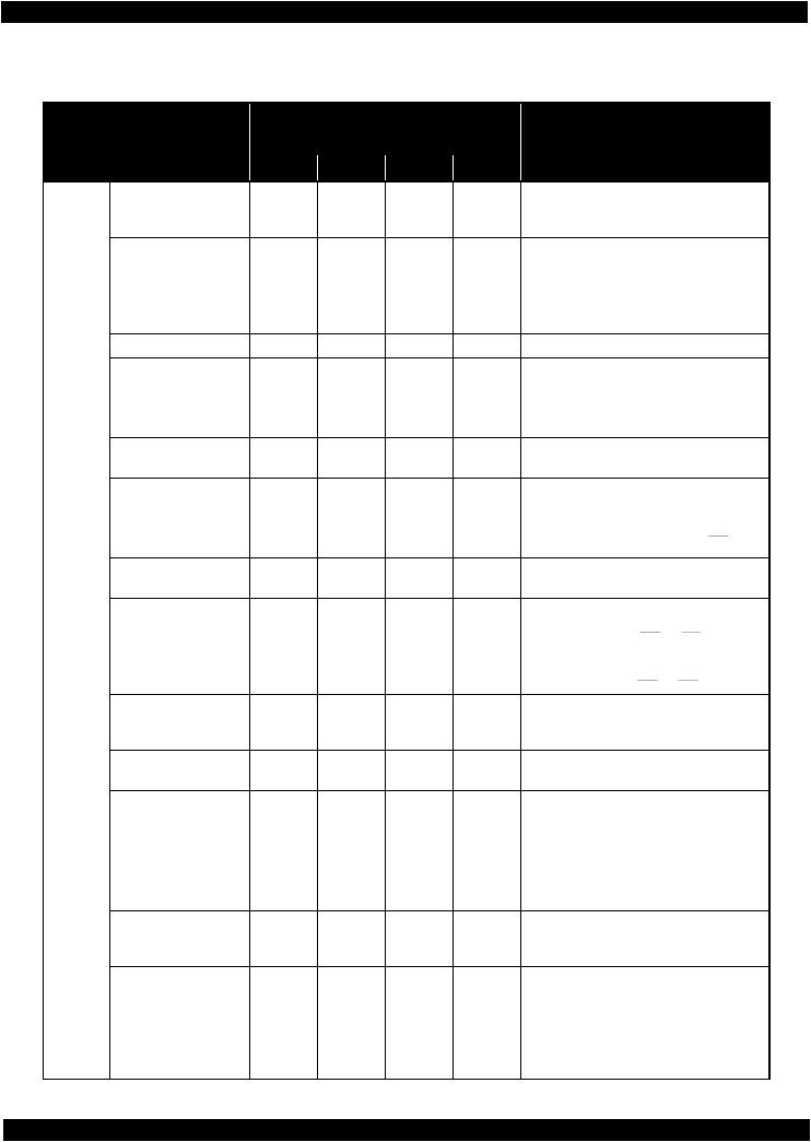
1.4.2 LEDs and LCD Indications
Table 1-8. LEDs and LCD Indications
Status
Printer fatal error
Printer fatal error (paper jam)
Scanner fatal error*1
ADF fatal error*1
ADF paper jam error*1
Waste ink pad end error
Waste ink pad near end error
Paper jam error
No paper cassette error
Paper out error
Operating Multi-feed error
Paper length mismatch error for duplex printing*3
Paper size mismatch error
Incorrect paper size error*1
Printer/printer driver mismatch error
Cover open error
Ink end error
Ink cartridge detection error
Ink cartridge detection error (non-Epson cartridge)
No ink cartridge error
WF-7010 series
LED
Power |
Network |
Paper |
|
Flash at |
Flash at |
Flash at |
|
high speed |
high speed |
high speed |
|
Flash at |
Flash at |
Flash at |
|
high speed |
high speed |
high speed |
|
--- |
--- |
--- |
|
--- |
--- |
--- |
|
--- |
--- |
--- |
|
Flash*2 |
--- |
Alternate |
|
flash 1 |
|||
|
|
||
Flash*2 |
--- |
Alternate |
|
flash 1 |
|||
|
|
||
Flash*2 |
--- |
Flash |
|
Flash*2 |
--- |
ON |
|
Flash*2 |
--- |
ON |
|
Flash*2 |
--- |
ON |
|
Flash*2 |
--- |
ON |
|
Flash*2 |
--- |
ON |
|
--- |
--- |
--- |
|
Flash*2 |
--- |
Flash at |
|
high speed |
|||
|
|
||
Flash |
--- |
Flash 2 |
|
Flash*2 |
--- |
--- |
|
Flash*2 |
--- |
--- |
|
Flash*2 |
--- |
--- |
|
Flash*2 |
--- |
--- |
|
WF-7520/7510 series |
|
Ink |
LCD Message |
|
|
||
Flash at |
Printer error. Turn power off and then on |
|
again. For details, see your documentation or |
||
high speed |
||
visit Epson.com. |
||
Flash at |
Paper jam inside, in back, or in ADF. Press |
|
high speed |
OK to see how to remove jammed paper. |
|
|
Scanner error. Turn power off and then on |
---again. In the error is not fixed, visit Epson.com for technical support.
---Automatic Document Feeder (ADF) error.
---Paper jam in the Automatic Document Feeder (ADF).
Alternate |
A printer's ink pad is at the end of its service |
flash 2 |
life. Please contact Epson Support. |
Alternate |
A printer's ink pad is nearing the end of its |
flash 2 |
service life. Please contact Epson Support. |
---Paper jam. Press OK to see how to remove jammed paper.
---Load Cassette correctly and press  or
or
 .
.
---Paper out or paper jam. Check paper size and load paper in paper cassette.
---Multi-page feed error. Remove and reload the paper, then press  or
or  .
.
---Incorrect paper size detected. Load correct paper size and press  or
or  .
.
No paper source matches paper size setting.
---Load appropriate paper in Cassette 1. Press
 or
or  .
.
---Paper size is incorrect. Load US B 11x17in size plain paper in Cassette.
Flash at high speed
Flash 2
ON*4
ON*4
ON*4
ON*4
Error Press  .
.
Close the scanner unit.
You need to replace the following ink cartridge(s).
<Ink Cartridges>XXXXXXX*5
Cannot recognize the following cartridge(s). Try installing them again.
<Ink Cartridges>XXXXXXX*5
Ink cartridge is not recognized. Please replace the cartridge.
<Ink Cartridges>XXXXXXX*5
The cartridge is installed incorrectly. Press it down until it clicks.
<Ink Cartridges>XXXXXXX*5
Product description |
Control Panel |
16 |

 Epson WF-7520/7510/7010 series
Status
Starting filling of ink (after carriage moves)
Ink cartridge cover open error
Starting initialization
Initializing
Filling of ink
Checking ink cartridges
Drying 1st side (printing from PC)
Printing (PC)
Printing nozzle check pattern
Printing printer status sheet
Printing (UPNP) Receiving data
Operating Canceling (PC)*6 Cleaning (PC) Print head cleaning
Canceling nozzle check pattern print
Canceling printer status sheet print
Initializing network
Waiting for network initialization
Network initialization (LED ON)
Network initialization (LED OFF)
Preparing to update firmware (cancel OK)
Updating firmware
Preparing to update firmware
Canceling firmware update
Revision A 
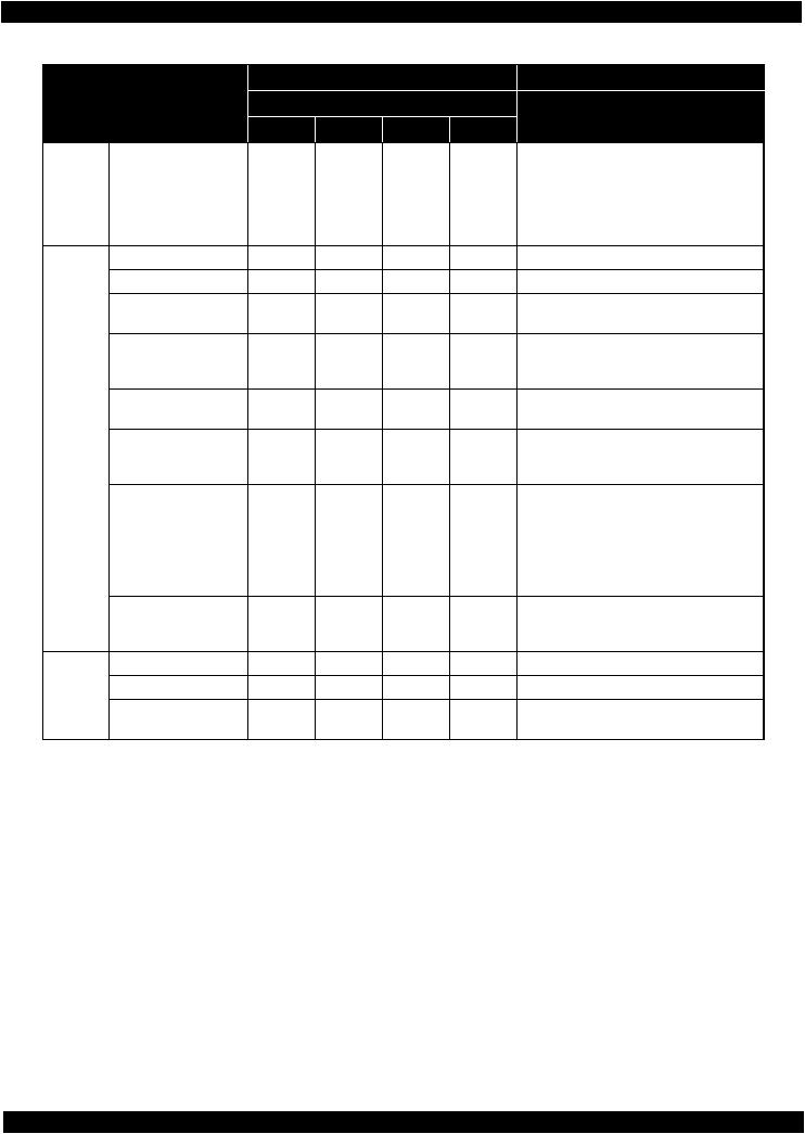
Table 1-8. LEDs and LCD Indications
WF-7010 series
LED
Power |
Network |
Paper |
|
Flash |
--- |
--- |
|
Flash*2 |
--- |
--- |
|
Flash |
--- |
--- |
|
Flash |
--- |
--- |
|
Flash |
--- |
--- |
|
Flash |
--- |
--- |
|
Flash |
--- |
--- |
|
Flash |
--- |
--- |
|
Flash |
--- |
--- |
|
Flash |
--- |
--- |
|
Flash |
Flash |
--- |
|
Flash |
Flash |
--- |
|
Flash |
--- |
--- |
|
Flash |
--- |
--- |
|
Flash |
--- |
--- |
|
Flash |
--- |
--- |
|
Flash |
--- |
--- |
|
Flash*2 |
Flash |
--- |
|
Flash*2 |
--- |
--- |
|
OFF*2 |
ON |
--- |
|
OFF*2 |
OFF |
--- |
|
ON*2 |
Flash at |
--- |
|
high speed |
|||
|
|
||
Flash*7 |
OFF |
OFF |
|
ON*2 |
Flash at |
--- |
|
high speed |
|||
|
|
||
ON*2 |
Flash at |
--- |
|
high speed |
|||
|
|
WF-7520/7510 series
LCD Message
Ink
Replace the cartridge(s) and close the
---scanner unit.
<Ink Cartridges>XXXXXXX*5
---The ink cartridge cover is open. Close the ink cartridge cover.
---Install the ink cartridges. See the setup sheet for details.
Initializing...Please wait.
---Do not turn off until initialization is complete. This takes about 7 minutes.
---Charging ink...Please wait.
---Checking the ink cartridges...
Printing 2-sided document. Do not touch the
---paper in the output tray until printing is complete.
---Printing...
---Printing...
---Printing...
---Printing...
---Receiving data...
---Canceling...
---Cleaning print head...Please wait.
---Cleaning print head...Please wait.
---Canceling...
---Canceling...
--- |
--- |
--- |
--- |
--- |
--- |
--- |
--- |
--- |
Preparing to update... |
|
Updating firmware...Do not turn power off. |
OFF |
It turns off and on automatically when |
|
complete. |
---Preparing to update...
---Canceling...
Product description |
Control Panel |
17 |
Epson WF-7520/7510/7010 series |
Revision A |
Table 1-8. LEDs and LCD Indications
Status
Operating
Standby
Operating/
Standby*8
Powering OFF
Powering ON
Feeding a paper (load/eject)
No error
Ink level low
Waste ink pad near end error
Requiring ink cartridges (carriage is at the replacement position)
Ink end error (during Bk mode)
Ink end error (out of Bk mode)
No ink cartridge error
Ink cartridge detection error
Ink cartridge detection error (non-Epson cartridge)
When starting up Not connected
Connected via wired LAN (with IP)
|
WF-7010 series |
|
WF-7520/7510 series |
||
|
LED |
|
LCD Message |
||
Power |
Network |
Paper |
Ink |
||
|
|||||
Flash at |
--- |
--- |
--- |
Turning off... |
|
high speed |
|||||
|
|
|
|
||
Flash |
Flash |
--- |
--- |
Starting up...Please wait. |
|
Flash |
--- |
--- |
--- |
Printing... |
|
ON |
--- |
--- |
--- |
--- |
|
ON*2 |
--- |
--- |
Flash*4 |
Ink low. |
|
ON*2 |
--- |
Alternate |
Alternate |
A printer's ink pad is nearing the end of its |
|
flash 1 |
flash 2 |
service life. Please contact Epson Support. |
|||
|
|
||||
|
|
|
|
Replace the cartridge(s) and close the |
|
Flash |
--- |
--- |
--- |
scanner unit. |
|
|
|
|
|
<Ink Cartridges>XXXXXXX*5 |
|
ON*2 |
--- |
--- |
ON*4 |
ON*2 |
--- |
--- |
ON*4 |
ON*2 |
--- |
--- |
ON*4 |
ON*2 |
--- |
--- |
ON*4 |
ON*2 |
--- |
--- |
ON*4 |
You can temporarily copy, print and fax in B&W on plain paper on the next job.
You need to replace the following ink cartridge(s).
<Ink Cartridges>XXXXXXX*5
The cartridge is installed incorrectly. Press it down until it clicks.
<Ink Cartridges>XXXXXXX*5
Cannot recognize the following cartridge(s). Try installing them again.
<Ink Cartridges>XXXXXXX*5
Ink cartridge is not recognized. Please replace the cartridge.
<Ink Cartridges>XXXXXXX*5
--- |
Flash |
--- |
--- |
--- |
--- |
--- |
--- |
--- |
--- |
--- |
ON |
--- |
--- |
--- |
Note : Flash Flash 2
Flash at high speed Alternate flash 1 Alternate flash 2
Turns on and off at intervals of 1.25 seconds.
On for 0.5 sec., Off for 0.5 sec., On for 0.5 sec. and Off for 1.0 sec. Turns on and off at intervals of 0.5 seconds.
Same as “Flash”
Turns on and off at intervals of 1.25 seconds.
Note *1: WF-7520/7510 series only
*2: Flashes if the status arises when printing starts or when the printer starts up, but lights if the status arises when printing is complete.
*3: WF-7520/7010 series only
*4: The corresponding ink LED flashes/lights.
*5: The corresponding ink cartridge product number is indicated. *6: Occurs when cancelling printing from PC, UPNP printing. *7: Lights and then flashes.
*8: This does not occur independently. Occurs together with operating or standby state.
Product description |
Control Panel |
18 |
Epson WF-7520/7510/7010 series |
Revision A |
1.5 Various Settings
1.5.1 Panel Operation
1.5.1.1 Setup Menu Configuration (WF-7520/7510 series only)
The following explains the setup menu structure and the outline of the menu functions.
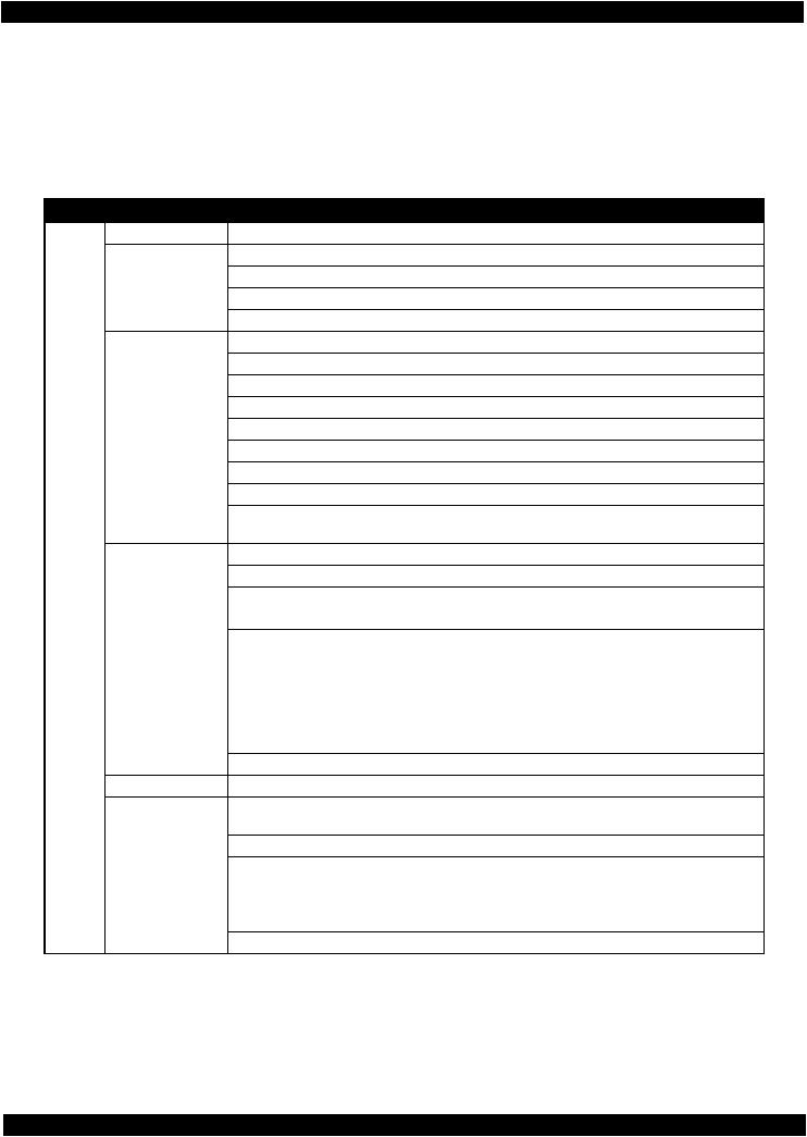
Table 1-9. Setup Menu Configuration (WF-7520/7510 series only)
|
Menu |
Description |
|
Setup |
Ink Levels |
--- |
Displays the status of ink cartridges. |
|
Maintenance |
Print Head Nozzle Check |
Prints a nozzle check pattern. |
|
|
Print Head Cleaning |
Runs a print head cleaning. |
|
|
Print Head Alignment |
Prints a gap adjustment pattern. |
|
|
Ink Cartridge Replacement |
Starts ink cartridge replacement. |
|
Printer Setup |
Paper Size Loaded*1 |
Selects the paper size. |
|
|
Sound |
Turns the sound on/off. |
|
|
Screen Saver*2 |
Configures the screen saver setting. |
|
|
Display Format |
Specifies display format for the images in the memory card. |
|
|
Date/Time |
Selects display format for data/time. |
|
|
Daylight Saving Time |
Selects daylight saving time. |
|
|
Country/Region |
Selects country/region. |
|
|
Language |
Selects the language displayed on the LCD. |
|
|
Paper Size Notice*1 |
Checks the paper size and selects whether to alert users when an |
|
|
|
error occurs (Off/On). |
|
Wi-Fi/Network |
Wi-Fi Setup |
Selects a connection method for wireless LAN. |
|
Settings |
General Network Setup |
Configures the general setting for network. |
|
|
||
|
|
Wi-Fi/Network Connection |
• Checks the network connection status. |
|
|
Check |
• Prints the connection check result. |
|
|
Confirm Network Settings |
• Displays the network information. |
|
|
|
• Prints a network status sheet. |
|
File Sharing Setup |
USB |
Sets the access priority when accessing the storage device |
|
|
Wi-Fi/Network |
connected to the USB host port to USB or Wi-Fi/Network. |
|
External Device |
Print Settings |
Configures the print and paper settings when printing an image in |
|
Setup |
|
external device. |
|
|
Photo Adjustments |
Configures the color correction for photo. |
|
Print Status Sheet |
--- |
Prints a printer status sheet. |
|
Restore Default |
Reset Fax Send/Receive |
Initializes the fax send/receive settings. |
|
Settings |
Settings |
|
|
|
||
|
|
Reset Fax Data Settings |
Deletes the fax data settings. |
|
|
Reset Wi-Fi/Network |
Initializes the Wi-Fi/network settings. |
|
|
Settings |
|
|
|
|
|
|
|
Reset All except Wi-Fi/ |
Initializes the settings except Wi-Fi/network/fax settings. |
|
|
Network & Fax Settings |
|
|
|
|
|
|
|
Reset All Settings |
Initializes the all settings. |
Note *1: |
WF-7520 series only |
|
|
*2: |
Not available for some destinations. |
|
|
Product description |
Various Settings |
19 |

Epson WF-7520/7510/7010 series |
Revision A |
1.5.1.2 Forced Power OFF (WF-7010 series only)
For WF-7010 series, the power can be turned off forcibly by the following panel operation. If the power is turned off forcibly, the same process of the normal power-off is executed.
Operation method
1.Press the power button and then stop button, and hold down the buttons for seven seconds or more.
2.When the Power LED starts flashing, release the buttons.
1.5.1.3 Printer Status Sheet
WF-7520/7510/7010 series print the printer status sheet by the following operation.
|
|
Table 1-10. Status Sheet |
Model |
|
Procedure |
WF-7520/7510 series |
1. |
Press the setup button. |
|
2. |
Select “Print Status Sheet” from the setup menu. |
|
3. |
Press the OK button. |
WF-7010 series |
Turn the power on while pressing the paper feed/eject button. |
Note : When printing the network status sheet to check the network information, follow the procedure below. |
|
WF-7520/7510 series: |
Select “Wi-Fi/Network Settings” - “Confirm Wi-Fi/Network Settings”, and press the OK button. |
|
(See "1.5.1.1 Setup Menu Configuration (WF-7520/7510 series only) (p19)".) |
WF-7010 series: |
Press the “network status sheet” button. (See "1.4.1 Operation Buttons (p14)".) |
Product description |
Various Settings |
20 |
CHAPTER 2
OPERATING PRINCIPLES

Epson WF-7520/7510/7010 series |
Revision A |
2.1 Overview
In this chapter, the product names are called as follows:
WF-7520 series: Epson WF-7525/Epson WF-7521/Epson WF-7520
WF-7510 series: Epson WF-7515/Epson WF-7511/Epson WF-7510
WF-7010 series: Epson WF-7018/Epson WF-7015/Epson WF-7012/Epson WF-7011/
Epson WF-7010
This chapter describes the operating principles of WF-7520/7510/7010 series printer mechanism.
2.2 Motors and Sensors
The following table lists the motors and sensors of WF-7520/7510/7010 series. Printer Mechanism
Table 2-1. List of Motors & Sensors (Printer Mechanism)
Mechanism |
Motor or Sensor |
No. |
Printhead |
|
--- |
Carriage mechanism |
CR Motor |
A |
|
CR Encoder |
1 |
|
PW Sensor |
2 |
|
Cover Open Sensor |
3 |
Paper loading/feed mechanism |
PF Motor |
B |
|
PF Encoder |
4 |
|
PE Sensor |
5 |
|
Pre-PE Sensor |
6 |
|
Paper Stopper Lever Sensor 1st |
7 |
|
1 |
A |
|
|
Printhead |
5 |
|
|
6 |
|
|
7 |
|
|
4
 2
2
 3
3
B
Figure 2-1. Motors & Sensors (Printer Mechanism)
Operating Principles |
Overview |
22 |

Epson WF-7520/7510/7010 series |
Revision A |
2nd cassette (WF-7520/7010 series only)
Table 2-2. List of Motors & Sensors (2nd Cassette)
Mechanism |
Motor or Sensor |
No. |
Paper loading/feed mechanism |
Pickup Motor |
A |
|
Pickup Encoder |
1 |
|
Paper Stopper Lever Sensor 2nd |
2 |
2 |
|
|
1
A
Figure 2-2. Motors & Sensors (2nd Cassette)
Operating Principles |
Motors and Sensors |
23 |

Epson WF-7520/7510/7010 series |
Revision A |
Scanner (WF-7520/7510 series only)
Table 2-3. List of Motors & Sensors (Scanner)
Mechanism |
Motor or Sensor |
No. |
Scanner mechanism |
Scanner Motor Assy |
A |
|
CIS Unit |
1 |
|
1 |
|
A


Figure 2-3. Motors & Sensors (Scanner)
Table 2-4. List of Motors & Sensors (ADF)
Mechanism |
|
Motor or Sensor |
No. |
ADF mechanism |
ADF Motor |
|
A |
|
ADF PE Sensor |
|
1 |
|
ADF DOC Sensor |
|
2 |
|
ADF Encoder |
|
3 |
2
3
A
1
Figure 2-4. Motors & Sensors (ADF)
Operating Principles |
Motors and Sensors |
24 |
Epson WF-7520/7510/7010 series |
Revision A |
2.3 Optical Sensor Control
WF-7520/7510/7010 series uses the optical sensor to control itself. The following describes the operating principles of optical sensor control.
Control method
To ensure accurate printing, each part must be controlled to make an adequate amount (time) of movement. The optical sensors read the amount (time) of movements as follows to printer to control it for achieving accurate printing.
1.Rotates the motors for control of the printer, and transmits drive force to the each part via the gear or the timing belt.
2.The encoder reads the drive amount of each part from the scale one by one to printer to monitor that the part drives for an adequate amount (time).
Controlled parts
The following table lists where the optical sensor control is used.
Table 2-5. Controlled Parts*1
Item |
Motor |
Scale |
Encoder |
Transmission method |
PF/ASF (1st cassette) |
PF Motor |
PF Scale |
PF Encoder |
PF Timing Belt |
CR |
CR Motor |
CR Scale |
CR Encoder |
CR Timing Belt |
ASF (2nd cassette*2) |
Pickup Motor |
Pickup Scale |
Pickup Encoder |
Gear |
ADF*3 |
ADF Motor |
ADF Scale |
ADF Encoder |
Gear |
Note *1: See Fig. 2-1 (p22) and Fig. 2-2 (p23) for the positions of the parts. *2: WF-7520/7010 series only
*3: WF-7520/7510 series only
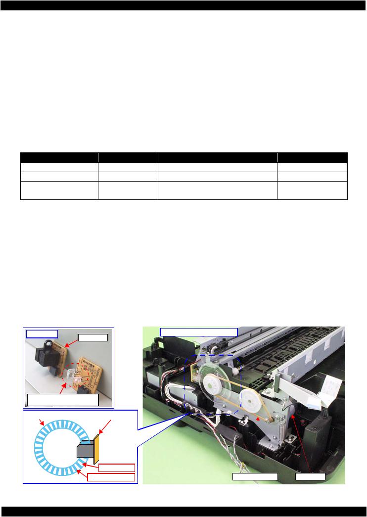
Operating principles
The following describes the PF drive control as an example of the actual operation for the optical sensor.
The PF scale consists of light-passing and light-blocking portions on its surface, and runs through the slit between the encoder’s light-emitting and light-receiving devices. While the printer is operating, the encoder always emits light from light-emitting device toward the light-receiving device, and the light-receiving device detects light when the light is transmitted through the light-passing portion of the scale, and does not detect light when the light is blocked by the light-blocking portion of the scale. According to the counts of light-detected and non detected times, the printer controls paper feed drive direction and amount.
When the encoder cannot read light-emitting/blocking counts correctly due to the misalignment, broken or contaminated scale, paper jam, foreign object and increasing a load, the fatal error occurs and the printer stops.
PF Encoder |
Left side of Printer Mechanism |
|
With cover |
Without cover (light-emitting and receiving devices)
PF Scale |
PF Encoder |
Light passes |
|
|
Light does not pass |
PF Timing Belt |
PF Motor |
Figure 2-5. PF Drive Control Section
Operating Principles |
Optical Sensor Control |
25 |

Epson WF-7520/7510/7010 series |
Revision A |
2.4 Power-On Sequence
This section describes the power-on sequences for this product. The preconditions are as follows.
Condition 1: Normal power-on sequence (See Table 2-6.)
Turning on the printer after turning it off without an error.
Initial ink charge has finished and every cartridge has sufficient ink.
No paper on the paper path.
The Printhead is capped with the Cap of the Ink System Assy.
The Carriage is normally fixed by the CR Lock.
Condition 2: Power-on sequence after recovering from a paper jam error (See Table 2-7.)
Turning on the printer after turning it off with a paper jam error.
There still remains paper on the paper path out of the detecting area of the PE sensor.
Table 2-6. Condition 1: Normal Power-on Sequence *1
Operation*2
1.Printhead initialization
1-1.Initializes the Printhead, and checks for the fuse on the board in the Printhead.*4
2.Checking for waste ink overflow
2-1.Checks the waste ink counter if the waste ink overflow is occurring.
3.Avoiding deadlock sequence *5
3-1.The carriage moves to the 0-digit side slowly and confirms it touches the Right Frame. 3-2.The carriage slightly moves to the 130-digit side slowly.
3-3.The PF Motor rotates clockwise, and releases the CR lock.
4.Seeking the home position
4-1.The carriage moves to the 0-digit side slowly and confirms it touches the Right Frame. The position when it touches the Right Frame is set as the origin position temporarily.
4-2.The carriage slowly moves to the CR lock set position.
4-3.The PF Motor rotates counterclockwise, and sets the CR lock.
4-4.The carriage moves to the 130-digit side slowly and confirms it touches the CR lock.
4-5.The carriage slowly moves toward the 0-digit side and reaches the CR lock set position.
4-6.The PF Motor rotates clockwise, and releases the CR lock.
4-7.The carriage moves to the 130-digit side slowly and confirms it does not touch the CR lock.
4-8.The carriage slowly moves to its home position, and the origin position is fixed.
Afterward, the carriage position is monitored according to the signals from the CR Encoder.
Carriage/PF Roller movement and position*3
130
%4 NQEM %4
130
130
130
130 |
|
%4 NQEM |
||||||||
|
|
KU TGNGCUGF |
||||||||
|
|
|
|
|
|
|
|
|
|
|
130
130
130
130
130
130
130
130
Operating Principles |
Power-On Sequence |
26 |
Loading...