


 Loading...
6-Axis Robots
VT series
MANIPULATOR MANUAL
Rev.6 |
EM19XR4170F |
MANIPULATOR MANUAL |
VT series Rev.6 |
6-Axis ROBOT
VT series Manipulator Manual
Rev.6
Copyright 2018-2019 SEIKO EPSON CORPORATION. All rights reserved.
VT Rev.6 |
i |
FOREWORD
Thank you for purchasing our robot products.
This manual contains the information necessary for the correct use of the manipulator. Please carefully read this manual and other related manuals before installing the robot system.
Keep this manual handy for easy access at all times.
WARRANTY
The Manipulator and its optional parts are shipped to our customers only after being subjected to the strictest quality controls, tests, and inspections to certify its compliance with our high performance standards.
Product malfunctions resulting from normal handling or operation will be repaired free of charge during the normal warranty period. (Please contact the supplier of your region for warranty period information.)
However, customers will be charged for repairs in the following cases (even if they occur during the warranty period):
1.Damage or malfunction caused by improper use which is not described in the manual, or careless use.
2.Malfunctions caused by customers’ unauthorized disassembly.
3.Damage due to improper adjustments or unauthorized repair attempts.
4.Damage caused by natural disasters such as earthquake, flood, etc.
Warnings, Cautions, Usage:
1.If the Manipulator or associated equipment is used outside of the usage conditions and product specifications described in the manuals, this warranty is void.
2.If you do not follow the WARNINGS and CAUTIONS in this manual, we cannot be responsible for any malfunction or accident, even if the result is injury or death.
3.We cannot foresee all possible dangers and consequences. Therefore, this manual cannot warn the user of all possible hazards.
ii |
VT Rev.6 |

TRADEMARKS
Microsoft, Windows, and Windows logo are either registered trademarks or trademarks of Microsoft Corporation in the United States and/or other countries. Other brand and product names are trademarks or registered trademarks of the respective holders.
NOTICE
No part of this manual may be copied or reproduced without authorization. The contents of this manual are subject to change without notice.
Please notify us if you should find any errors in this manual or if you have any comments regarding its contents.
MANUFACTURER
CONTACT INFORMATION
Contact information is described in “SUPPLIERS” in the first pages of the following manual:
Robot System Safety and Installation Read this manual first
VT Rev.6 |
iii |

Regarding battery disposal
The crossed out wheeled bin label that can be found on your product indicates that this product and incorporated batteries should not be disposed of via the normal household waste stream. To prevent possible harm to the environment or human health please separate this product and its batteries from other waste streams to ensure that it can be recycled in an environmentally sound manner. For more details on available collection facilities please contact your local government office or the retailer where you purchased this product. Use of the chemical symbols Pb, Cd or Hg indicates if these metals are used in the battery.
This information only applies to customers in the European Union, according to DIRECTIVE 2006/66/EC OF THE EUROPEAN PARLIAMENT AND OF THE COUNCIL OF 6 September 2006 on batteries and accumulators and waste batteries and accumulators and repealing Directive 91/157/EEC and legislation transposing and implementing it into the various national legal systems.
For other countries, please contact your local government to investigate the possibility of recycling your product.
The battery removal/replacement procedure is described in the following manuals:
VT series manipulator manual
Maintenance: 18.4 Replacing the Lithium Battery
iv |
VT Rev.6 |

Before Reading This Manual
This section describes what you should know before reading this manual.
Structure of Robot System
The VT series Manipulators can be used with the following combinations of software.
VT6-A901S, VT6-A901C, VT6-A901P |
Controller Firmware |
|
Ver.7.4.56.2 or later |
||
|
EPSON RC+ 7.0 |
Before Ver. 7.4.6 |
!!! |
|
Ver.7.4.7 or later |
OK |
||
|
OK: Compatible All functions of the EPSON RC+ 7.0 and the robot system are available.
!!!: Compatible Connection is OK. It is recommended to use the following version or later. Display or control may not be operated properly.
EPSON RC+ 7.0 Ver.7.4.7
Shape of Motors
The shape of the motors used for the Manipulator that you are using may be different from the shape of the motors described in this manual because of the specifications.
Setting by Using Software
This manual contains setting procedures by using software. They are marked with the following icon.
EPSON
RC+
VT Rev.6 |
v |
vi |
VT Rev.6 |

TABLE OF CONTENTS
Setup & Operation
|
|
|
1. Safety |
3 |
|
1.1 |
Conventions......................................................................................... |
3 |
1.2 |
Design and Installation Safety............................................................. |
4 |
1.3 |
Operation Safety.................................................................................. |
5 |
1.4 |
Emergency Stop.................................................................................. |
7 |
1.5 |
How to Move Arms with the Electromagnetic Brake........................... |
9 |
|
1.5.1 Arm Motions............................................................................. |
9 |
|
1.5.2 Release the Brake by the Software....................................... |
10 |
1.6 |
Precaution for Operation in Low Power Status................................. |
10 |
1.7 |
Labels ................................................................................................ |
11 |
|
|
|
2. Specifications |
13 |
|
2.1 |
Features of VT series Manipulators .................................................. |
13 |
2.2 |
Model Number................................................................................... |
13 |
2.3 |
Part Names........................................................................................ |
14 |
2.4 |
Outer Dimensions.............................................................................. |
16 |
2.5 |
Standard Motion Range .................................................................... |
18 |
2.6 |
System Example................................................................................ |
20 |
2.7 |
Specifications .................................................................................... |
21 |
2.8 |
How to Set the Model ........................................................................ |
25 |
|
|
||
3. Environments and Installation |
26 |
||
3.1 |
Environmental Conditions ................................................................. |
26 |
|
3.2 |
Base Table ........................................................................................ |
27 |
|
3.3 |
Mounting Dimensions........................................................................ |
29 |
|
3.4 |
Unpacking and Transportation .......................................................... |
30 |
|
3.5 |
Installation Procedure........................................................................ |
31 |
|
3.6 |
Power Supply .................................................................................... |
32 |
|
|
3.6.1 |
Specifications......................................................................... |
32 |
|
3.6.2 |
AC Power Cable .................................................................... |
33 |
|
3.6.3 |
Breaker .................................................................................. |
34 |
|
3.6.4 |
Grounding.............................................................................. |
34 |
3.7 |
Connecting the Cables ...................................................................... |
35 |
|
|
3.7.1 |
Connection Example ............................................................. |
35 |
|
3.7.2 |
Noise Countermeasures........................................................ |
38 |
3.8 |
Relocation and Storage..................................................................... |
39 |
|
|
3.8.1 Precautions for Relocation and Storage ............................... |
39 |
|
|
3.8.2 |
Relocation.............................................................................. |
40 |
3.9 |
Checking the Basic Orientation......................................................... |
42 |
|
3.10 |
Origin Position Label ....................................................................... |
42 |
|
VT Rev.6 |
vii |

TABLE OF CONTENTS
|
|
||
4. Setting of End Effectors |
43 |
||
4.1 |
Attaching an End Effector .................................................................. |
43 |
|
4.2 |
Attaching Cameras and Air Valves .................................................... |
44 |
|
4.3 |
Weight and Inertia Settings................................................................ |
44 |
|
|
4.3.1 |
Weight Setting ........................................................................ |
47 |
|
4.3.2 |
INERTIA Setting ..................................................................... |
50 |
4.4 |
Precautions for Auto Acceleration/Deceleration of Joint #3 .............. |
54 |
|
|
|
|
5. Motion Range |
55 |
|
5.1 |
Motion Range Setting by Pulse Range (for All Joints)....................... |
55 |
|
5.1.1 Max. Pulse Range of Joint #1 ................................................ |
56 |
|
5.1.2 Max. Pulse Range of Joint #2 ................................................ |
56 |
|
5.1.3 Max. Pulse Range of Joint #3 ................................................ |
57 |
|
5.1.4 Max. Pulse Range of Joint #4 ................................................ |
57 |
|
5.1.5 Max. Pulse Range of Joint #5 ................................................ |
57 |
|
5.1.6 Max. Pulse Range of Joint #6 ................................................ |
58 |
5.2 |
Motion Range Setting by Mechanical Stops...................................... |
59 |
|
5.2.1 Motion Range Setting of Joint #1........................................... |
59 |
|
5.2.2 Motion Range Setting of Joint #2........................................... |
60 |
|
5.2.3 Motion Range Setting of Joint #3........................................... |
61 |
5.3 |
Restriction of Manipulator Operation by Joint Angle Combination.... |
62 |
5.4 |
Coordinate System............................................................................. |
63 |
5.5 |
Changing the Robot ........................................................................... |
64 |
5.6 |
Setting the Cartesian (Rectangular) Range in the XY Coordinate |
|
|
System of the Manipulator................................................................. |
65 |
|
|
|
6. Operation Mode & LED |
66 |
|
6.1 |
Overview ............................................................................................ |
66 |
6.2 |
Switch Operation Mode...................................................................... |
66 |
6.3 |
Program Mode (AUTO) ...................................................................... |
67 |
|
6.3.1 What is Program Mode (AUTO)?........................................... |
67 |
|
6.3.2 Setup from EPSON RC+ 7.0.................................................. |
67 |
6.4 |
Auto Mode (AUTO) ............................................................................ |
68 |
|
6.4.1 What is Auto mode (AUTO)? ................................................. |
68 |
|
6.4.2 Setup from EPSON RC+ 7.0.................................................. |
68 |
|
6.4.3 Setup from Control Device..................................................... |
69 |
6.5 |
LED..................................................................................................... |
70 |
|
|
|
|
|
7. Development PC Connection Port |
71 |
|
7.1 |
What is Development PC Connection Port........................................ |
71 |
|
7.2 |
Precaution .......................................................................................... |
72 |
|
7.3 |
Software Setup and Connection Check............................................. |
72 |
|
7.4 |
Disconnection of Development PC and Manipulator......................... |
73 |
|
viii |
|
VT Rev.6 |
|
TABLE OF CONTENTS
|
|
||
8. Memory Port |
74 |
||
8.1 |
What is Controller Status Storage Function?.................................... |
74 |
|
8.2 |
Before Using Controller Status Storage Function............................. |
74 |
|
|
8.2.1 |
Precautions............................................................................ |
74 |
|
8.2.2 |
Adoptable USB Memory........................................................ |
75 |
8.3 |
Controller Status Storage Function................................................... |
75 |
|
|
8.3.1 |
Controller Status Storage ...................................................... |
75 |
|
8.3.2 Load Data with EPSON RC+ 7.0 .......................................... |
76 |
|
|
8.3.3 |
Transfer with E-mail............................................................... |
77 |
8.4 |
Details of Data................................................................................... |
78 |
|
|
|
|
9. LAN (Ethernet Communication) Port |
79 |
|
9.1 |
What is the LAN (Ethernet Communication) Port ............................. |
79 |
9.2 |
IP Address ......................................................................................... |
80 |
9.3 |
Changing Manipulator IP Address .................................................... |
80 |
9.4 |
Connection of Development PC and Manipulator with Ethernet ...... |
81 |
9.5 |
Disconnection of Development PC and Manipulator with Ethernet.. |
83 |
|
|
|
|
|
|
10. TP Port |
|
84 |
|
10.1 |
What is the TP Port? ....................................................................... |
84 |
||
10.2 |
Teach Pendant Connection............................................................. |
84 |
||
|
|
|
|
|
|
11. Options |
|
85 |
|
11.1 |
Camera Plate Unit ........................................................................... |
85 |
||
11.2 |
Tool Adapter (ISO flange) ............................................................... |
87 |
||
11.3 |
Adjustable Mechanical Stops .......................................................... |
88 |
||
11.4 |
External Wiring Kit........................................................................... |
88 |
||
|
|
|
||
|
12. EMERGENCY |
95 |
||
12.1 |
Safeguard Switch and Latch Release Switch ................................. |
95 |
||
|
|
12.1.1 |
Safeguard Switch ................................................................ |
96 |
|
|
12.1.2 |
Latch Release Switch.......................................................... |
97 |
|
|
12.1.3 Checking Latch Release Switch Operation......................... |
97 |
|
12.2 |
Emergency Stop Switch Connection............................................... |
98 |
||
|
|
12.2.1 |
Emergency Stop Switch ...................................................... |
98 |
|
|
12.2.2 Checking Emergency Stop Switch Operation ..................... |
98 |
|
|
|
12.2.3 Recovery from Emergency Stop ......................................... |
98 |
|
12.3 |
Pin Assignments.............................................................................. |
99 |
||
12.4 |
Circuit Diagrams............................................................................ |
100 |
||
|
|
12.4.1 Example 1: External emergency stop switch typical application |
||
|
|
......................................................................................................... |
|
100 |
|
|
12.4.2 Example 2: External safety relay typical application......... |
101 |
|
VT Rev.6 |
|
|
ix |
|

TABLE OF CONTENTS
|
|
|
13. Standard I/O Connector |
102 |
|
13.1 |
Standard, Cleanroom Model.......................................................... |
102 |
|
13.1.1 Input Circuit (Standard, Cleanroom Model) ....................... |
102 |
|
13.1.2 Output Circuit (Standard, Cleanroom Model) .................... |
105 |
13.2 |
Protection Model ............................................................................ |
108 |
|
13.2.1 Input Circuit (Protection Model) ......................................... |
108 |
|
13.2.2 Output Circuit (Protection Model)....................................... |
110 |
|
13.2.3 Pin Assignments of Input and Output Circuit |
|
|
(Protection Model) ............................................................. |
112 |
13.3 |
I/O Cable Product Procedure......................................................... |
113 |
|
13.3.1 I/O Cable Connecting Method............................................ |
113 |
|
13.3.2 How to Fix the I/O Cable .................................................... |
113 |
|
|
|
||
14. |
I/O Remote Settings |
114 |
||
|
14.1 |
I/O Signal Description .................................................................... |
115 |
|
|
|
14.1.1 |
Remote Input Signals......................................................... |
115 |
|
|
14.1.2 |
Remote Output Signals ...................................................... |
119 |
|
14.2 |
Timing Specifications ..................................................................... |
122 |
|
|
|
14.2.1 Precautions for Remote Input Signals ............................... |
122 |
|
|
|
14.2.2 Timing Diagram for Operation Execution Sequence ......... |
122 |
|
|
|
14.2.3 Timing Diagram for Program Execution Sequence ........... |
122 |
|
|
|
14.2.4 Timing Diagram for Safety Door Input Sequence.............. |
123 |
|
|
|
14.2.5 Timing Diagram for Emergency Stop Sequence ............... |
123 |
|
|
|
|
||
15. |
SD Card Slot |
124 |
||
|
|
|
||
16. |
RESET Switch |
125 |
||
|
|
|
|
|
17. |
Fieldbus I/O |
|
126 |
|
x |
VT Rev.6 |
|
|
|
TABLE OF CONTENTS |
|
Maintenance |
|
|
|
|
|
|
|
||
|
1. Safety Maintenance |
131 |
||
|
|
|
||
|
2. General Maintenance |
132 |
||
2.1 |
Maintenance Inspection .................................................................. |
132 |
||
|
|
2.1.1 Schedule for Maintenance Inspection ................................. |
132 |
|
|
|
2.1.2 |
Inspection Point ................................................................... |
133 |
2.2 |
Overhaul (Parts Replacement)........................................................ |
134 |
||
2.3 |
Tightening Hexagon Socket Head Cap Bolts.................................. |
136 |
||
2.4 |
Matching Origins.............................................................................. |
136 |
||
2.5 |
Layout of Maintenance Parts .......................................................... |
137 |
||
|
|
|
||
|
3. Manipulator Structure |
138 |
||
|
|
|
|
|
|
4. Alarm |
|
|
140 |
4.1 |
Maintenance .................................................................................... |
141 |
||
4.2 |
Maintenance Information................................................................. |
142 |
||
|
|
4.2.1 How to Check the Maintenance Information ....................... |
142 |
|
|
|
4.2.2 How to Edit the Maintenance Information ........................... |
143 |
|
|
|
4.2.3 |
Alarm Notifying Method ....................................................... |
144 |
|
|
4.2.4 How to Cancel the Alarm..................................................... |
144 |
|
|
|
|
||
|
5. Backup and Restore |
145 |
||
5.1 |
What is the Backup Controller Function.......................................... |
145 |
||
5.2 |
Backup Data Types ......................................................................... |
145 |
||
5.3 |
Backup............................................................................................. |
146 |
||
5.4 |
Restore ............................................................................................ |
147 |
||
|
|
|
||
|
6. Firmware Update |
150 |
||
6.1 |
Updating Firmware .......................................................................... |
150 |
||
6.2 |
Firmware Upgrade Procedure......................................................... |
150 |
||
6.3 |
Manipulator Recovery ..................................................................... |
152 |
||
6.4 |
Firmware Initialization Procedure.................................................... |
153 |
||
|
|
|
|
|
|
7. Covers |
|
155 |
|
7.1 |
Arm #1 Cover .................................................................................. |
156 |
||
7.2 |
Arm #2 Cover .................................................................................. |
158 |
||
7.3 |
Arm #3 Cover .................................................................................. |
159 |
||
7.4 |
Arm #4 Cover 1 ............................................................................... |
160 |
||
7.5 |
Arm #4 Cover 2 ............................................................................... |
161 |
||
VT Rev.6 |
|
|
xi |
|

TABLE OF CONTENTS |
|
|
7.6 |
Power Cable Cover .......................................................................... |
163 |
7.7 |
Connector Plate ............................................................................... |
164 |
8. Cable |
|
166 |
8.1 |
Replacing Cable Unit ....................................................................... |
167 |
8.2 Insert or Pull out of Power Cable ..................................................... |
183 |
|
9. Joint #1 |
184 |
|
9.1 Replacing Joint #1 Motor ................................................................. |
185 |
|
9.2 Replacing Joint #1 Reduction Gear Unit.......................................... |
189 |
|
9.3 Replacing Joint #1 Timing Belt ........................................................ |
190 |
|
10. Joint #2 |
195 |
|
10.1 |
Replacing Joint #2 Motor ............................................................... |
196 |
10.2 |
Replacing Joint #2 Reduction Gear Unit........................................ |
202 |
10.3 |
Replacing Joint #2 Timing Belt ...................................................... |
203 |
11. Joint #3 |
204 |
|
11.1 |
Replacing Joint #3 Motor ............................................................... |
205 |
11.2 |
Replacing Joint #3 Reduction Gear Unit........................................ |
211 |
11.3 |
Replacing Joint #3 Timing Belt ...................................................... |
212 |
12. Joint #4 |
213 |
|
12.1 |
Replacing Joint #4 Motor ............................................................... |
214 |
12.2 |
Replacing Joint #4 Reduction Gear Unit........................................ |
219 |
12.3 |
Replacing Joint #4 Timing Belt ...................................................... |
220 |
13. Joint #5 |
224 |
|
13.1 |
Replacing Joint #5 Motor ............................................................... |
225 |
13.2 |
Replacing Joint #5 Reduction Gear Unit........................................ |
229 |
13.3 |
Replacing Joint #5 Timing Belt ...................................................... |
230 |
14. Joint #6 |
231 |
|
14.1 |
Replacing Joint #6 Motor ............................................................... |
232 |
14.2 |
Replacing Joint #6 Reduction Gear Unit........................................ |
236 |
14.3 |
Replacing Joint #6 Timing Belt ...................................................... |
237 |
15. AMP Board |
238 |
|
15.1 |
Replacing AMP Board on Joint #1, #2, and #3.............................. |
240 |
15.2 |
Replacing AMP Board on Joint #4................................................. |
242 |
15.3 |
Replacing AMP Board on Joint #5 and #6..................................... |
243 |
xii |
|
VT Rev.6 |
|
|
|
TABLE OF CONTENTS |
|
|
|
|
|
|
|
16. LED Plate |
|
244 |
|
16.1 |
Replacing LED Plate ..................................................................... |
245 |
||
|
|
|
|
|
|
17. Felt Sheet |
|
246 |
|
17.1 |
Replacing Joint #2 Felt Sheet ....................................................... |
247 |
||
17.2 |
Replacing Joint #3 Felt Sheet ....................................................... |
248 |
||
|
|
|
||
|
18. Controller Unit |
249 |
||
18.1 |
Replacing Controller Unit .............................................................. |
250 |
||
|
|
18.1.1 |
Standard, Cleanroom Model ............................................. |
251 |
|
|
18.1.2 |
Protection Model................................................................ |
254 |
18.2 |
Replacing Power Board................................................................. |
258 |
||
18.3 |
Replacing CPU/DPB Board........................................................... |
259 |
||
18.4 |
Replacing Lithium Battery ............................................................. |
261 |
||
18.5 |
Replacing Cooling Fan.................................................................. |
261 |
||
18.6 |
Replacing SD Card........................................................................ |
262 |
||
|
|
18.6.1 |
Standard, Cleanroom Model ............................................. |
262 |
|
|
18.6.2 |
Protection Model................................................................ |
263 |
|
|
|
|
|
|
19. Calibration |
|
264 |
|
19.1 |
Overview........................................................................................ |
264 |
||
19.2 |
Calibration Procedures.................................................................. |
267 |
||
|
|
|
|
|
|
20. Restrictions |
|
271 |
|
20.1 |
Commands Cannot Use................................................................ |
271 |
||
20.2 |
Commands Cause Motion Error If Specifying RS-232C............... |
271 |
||
20.3 |
Commands Cause Error................................................................ |
272 |
||
|
|
20.3.1 |
Conveyor Tracking Commands......................................... |
272 |
|
|
20.3.2 |
PG Commands .................................................................. |
273 |
|
|
20.3.3 |
R-I/O Commands............................................................... |
273 |
|
|
20.3.4 |
Force Sensing Commands................................................ |
273 |
|
|
20.3.5 |
Other (FineDist) ................................................................. |
273 |
|
|
20.3.6 |
Other (HealthCalcPeriod) .................................................. |
273 |
|
|
20.3.7 |
Other (ChDisk)................................................................... |
273 |
20.4 |
Restrictions of Functions............................................................... |
274 |
||
|
|
20.4.1 |
TP3 .................................................................................... |
274 |
|
|
20.4.2 |
Loop Processing................................................................ |
274 |
|
|
20.4.3 Camera Searching by CV1/CV2........................................ |
275 |
|
|
|
20.4.4 Restore the Data of Backup Controller Function .............. |
275 |
|
VT Rev.6 |
xiii |

TABLE OF CONTENTS
|
|
|
21. |
Error Code Table |
276 |
|
|
|
22. |
Maintenance Parts List |
277 |
|
|
|
Appendix A: Open Source Software License |
279 |
|
xiv |
VT Rev.6 |

Setup & Operation
This volume contains information for setup and operation of the VT series Manipulators.
Please read this volume thoroughly before setting up and operating the Manipulators.

Setup & Operation 1. Safety
1. Safety
Installation and transportation of Manipulators and robotic equipment shall be performed by qualified personnel and should conform to all national and local codes. Please read this manual and other related manuals before installing the robot system or before connecting cables.
Keep this manual handy for easy access at all times.
1.1 Conventions
Important safety considerations are indicated throughout the manual by the following symbols. Be sure to read the descriptions shown with each symbol.
|
This symbol indicates that a danger of possible serious injury or |
WARNING |
death exists if the associated instructions are not followed |
properly. |
|
|
|
|
This symbol indicates that a danger of possible serious injury or |
WARNING |
death caused by electric shock exists if the associated |
instructions are not followed properly. |
|
|
|
|
This symbol indicates that a danger of possible harm to people |
CAUTION |
or physical damage to equipment and facilities exists if the |
associated instructions are not followed properly. |
|
|
|
VT Rev.6 |
3 |

Setup & Operation 1. Safety
1.2 Design and Installation Safety
Only trained personnel should design and install the robot system. Trained personnel are defined as those who have taken robot system training and maintenance training classes held by the manufacturer, dealer, or local representative company, or those who understand the manuals thoroughly and have the same knowledge and skill level as those who have completed the training courses.
To ensure safety, a safeguard must be installed for the robot system. For details on the safeguard, refer to the Installation and Design Precautions in the Safety chapter of the EPSON RC+ User’s Guide.
The following items are safety precautions for design personnel:
■Personnel who design and/or construct the robot system with this product must read the Safety chapter in the EPSON RC+ User’s Guide to understand the safety requirements before designing and/or constructing the robot system. Designing and/or constructing the robot system without understanding the safety requirements is extremely hazardous, may result in serious bodily injury and/or severe equipment damage to the robot system, and may cause serious safety problems.
■The robot system must be used within the environmental conditions described in
their respective manuals. This product has been designed and manufactured WARNING strictly for use in a normal indoor environment. Using the product in an
environment that exceeds the specified environmental conditions may not only shorten the life cycle of the product but may also cause serious safety problems.
■The robot system must be used within the installation requirements described in the manuals. Using the robot system outside of the installation requirements may not only shorten the life cycle of the product but also cause serious safety problems.
Further precautions for installation are mentioned in Setup & Operation: 3. Environments and Installation. Please read this chapter carefully to understand safe installation procedures before installing the robots and robotic equipment.
4 |
VT Rev.6 |
Setup & Operation 1. Safety
1.3 Operation Safety
The following items are safety precautions for qualified Operator personnel:
■Please carefully read the 1.3 Safety-related Requirements in the Safety chapter of the Safety and Installation manual before operating the robot system. Operating the robot system without understanding the safety requirements is extremely hazardous and may result in serious bodily injury and/or severe equipment damage to the robot system.
■Do not enter the operating area of the Manipulator while the power to the robot system is turned ON. Entering the operating area with the power ON is extremely hazardous and may cause serious safety problems as the Manipulator may move even if it seems to be stopped.
■Before operating the robot system, make sure that no one is inside the
WARNING |
safeguarded area. The robot system can be operated in the mode for teaching |
|
even when someone is inside the safeguarded area. |
||
|
||
|
The motion of the Manipulator is always in restricted (low speed and low power) |
|
|
status to secure the safety of an operator. However, operating the robot system |
|
|
while someone is inside the safeguarded area is extremely hazardous and may |
|
|
result in serious safety problems in case that the Manipulator moves unexpectedly. |
■Immediately press the Emergency Stop switch whenever the Manipulator moves abnormally while the robot system is operated. Continuing the operation while the Manipulator moves abnormally is extremely hazardous and may result in serious bodily injury and/or severe equipment damage to the robot system.
■To shut off power to the robot system, disconnect the power plug from the power source. Be sure to connect the AC power cable to a power receptacle.
DO NOT connect it directly to a factory power source.
■Before performing any replacement procedure, turn OFF the robot system and related equipment, and then disconnect the power plug from the power source. Performing any replacement procedure with the power ON is extremely hazardous and may result in electric shock and/or malfunction of the robot system.
WARNING ■ Do not connect or disconnect the motor connectors while the power to the robot system is turned ON. Connecting or disconnecting the motor connectors with the power ON is extremely hazardous and may result in serious bodily injury as the Manipulator may move abnormally, and also may result in electric shock and/or malfunction of the robot system.
VT Rev.6 |
5 |
Setup & Operation 1. Safety
■Whenever possible, only one person should operate the robot system. If it is necessary to operate the robot system with more than one person, ensure that all people involved communicate with each other as to what they are doing and take all necessary safety precautions.
■Each Joint:
If the joints are operated repeatedly with the operating angle less than 5 degrees, the Manipulator may get damaged early due to the bearings are not being covered with grease during movement. To prevent early breakdown, move the joints larger than 30 degrees for about five to ten times a day.
■Vibration (resonance) may occur continuously depending on the combination of
CAUTION |
robot motion speed, Arm orientation, and end effector load. Vibration arises from |
|
natural vibration frequency of the Arm and can be controlled by following |
|
measures. |
|
Changing Manipulator speed |
|
Changing the teach points |
|
Changing the end effector load |
■Manipulator may be heated due to motor heat etc. Do not touch the Manipulator until temperature falls. After confirming that the temperature of the Manipulator falls and is not hot when you touch it. Then perform teaching or maintenance.
6 |
VT Rev.6 |

Setup & Operation 1. Safety
1.4 Emergency Stop
If the Manipulator moves abnormally during operation, immediately press the Emergency Stop switch. Pressing the Emergency Stop switch immediately changes the Manipulator to deceleration motion and stops it at the maximum deceleration speed.
However, avoid pressing the Emergency Stop switch unnecessarily while the Manipulator is running normally. Pressing the Emergency Stop switch locks the brake and it may cause wear on the friction plate of the brake, resulting in the short life of the brake.
Normal brake life cycle: About 2 years (when the brakes are used 100 times/day)
To place the system in emergency mode during normal operation, press the Emergency Stop switch when the Manipulator is not moving.
Refer to the Setup & Operation: 12. EMERGENCY for instructions on how to wire the Emergency Stop switch circuit.
Do not turn OFF the power while the Manipulator is operating.
If you attempt to stop the Manipulator in emergency situations such as “Safeguard Open”, make sure to stop the Manipulator using the Emergency Stop switch.
If the Manipulator is stopped by turning OFF the power while it is operating, following problems may occur.
Reduction of the life and damage of the reduction gear unit Position gap at the joints
In addition, if the Manipulator was forced to be turned OFF by blackouts and the like while the Manipulator is operating, make sure to check the following points after power restoration.
Whether or not the reduction gear is damaged Whether or not the joints are in their proper positions
If there is a position gap, perform calibration by referring to the Maintenance 19. Calibration in this manual. Also, the same troubles may occur if an error occurs and the Manipulator stops in emergency during the operation. Check the Manipulator condition and perform calibration if necessary.
Before using the Emergency Stop switch, be aware of the following.
-The Emergency Stop (E-STOP) switch should be used to stop the Manipulator only in case of emergencies.
-To stop the Manipulator operating the program except in emergency, use Pause (halt) or STOP (program stop) commands
Pause and STOP commands do not turn OFF the motors. Therefore, the brake does not function.
-For the Safeguard system, do not use the circuit for E-STOP.
For details of the Safeguard system, refer to the following manuals.
EPSON RC+ User’s Guide
2. Safety - Installation and Design Precautions - Safeguard System
Safety and Installation
2.5 Connection to EMERGENCY Connector
VT Rev.6 |
7 |

Setup & Operation 1. Safety
To check brake problems, refer to the following manuals.
Manipulator Manual Maintenance
2.1.2Inspection Point - Inspection While the Power is ON (Manipulator is operating)
Safety and Installation
5.1.1Manipulator
-Inspection While the Power is ON (Manipulator is operating)
Free running distance in emergency
The operating Manipulator cannot stop immediately after the Emergency Stop switch is pressed.
The free running time/angle/distance of the Manipulator are shown below. However, remember that the values vary depending on following conditions.
Weight of the end effector |
Weight setting |
Weight of workpiece |
Speed setting |
Operating pose |
Accel setting |
Conditions for measurement
|
|
|
|
VT series |
||
ACCEL Setting |
|
100 |
|
|||
SPEED Setting |
|
100 |
|
|||
Load [kg] |
|
6 |
|
|||
WEIGHT Setting |
|
6 |
|
|||
|
|
|
|
|
|
|
|
|
|
|
|
VT6-A901** |
|
|
Arm #1 |
|
0.2 |
|
||
Free |
Arm #2 |
|
0.3 |
|
||
|
|
|
0.2 |
|
||
running |
Arm #3 |
|
|
|||
time |
Arm #4 |
|
0.2 |
|
||
[sec.] |
|
|
|
|
|
|
Arm #5 |
|
0.2 |
|
|||
|
|
|
||||
|
Arm #6 |
|
0.2 |
|
||
|
|
Table Top |
|
50 |
|
|
|
Arm #1 |
Ceiling |
|
|
||
|
|
|
|
|||
Free |
Wall |
|
30 |
|
||
|
|
|
||||
Arm #2 |
|
70 |
|
|||
running |
|
|
||||
angle |
Arm #3 |
|
20 |
|
||
[°] |
Arm #4 |
|
20 |
|
||
|
Arm #5 |
|
20 |
|
||
|
Arm #6 |
|
30 |
|
||
8 |
VT Rev.6 |
Setup & Operation 1. Safety
1.5 How to Move Arms with the Electromagnetic Brake
NOTE
When the electromagnetic brake is operating such as an emergency status, all arms cannot be moved.
For procedures to release the electromagnetic brake, refer to the following section. When the electromagnetic brake is released, the arms can be moved by hand.
1.5.2Release the Brake by the Software
(When the software is available)
In an emergency situation such as you cannot /do not want to turn ON the power, you can forcibly move the robot arm by pushing or pulling it with strong force.
A measure of force: 500N (near Arm #6)
However, if moving the robot forcibly, the joints may get damage. Be sure to do this only in an emergency situation.
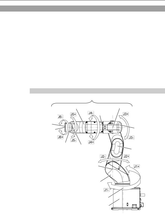
1.5.1Arm Motions
|
Upper Arm (Arms #3 to #6) |
|
|
Arm #4 |
Joint #3 |
|
Joint #4 |
|
Arm #6 |
|
|
Joint #6 |
|
Arm #3 |
|
|
|
Arm #5 |
Joint #5 |
|
|
Arm #2 |
|
|
|
Joint #2
|
Arm #1 |
(Lower Arm) |
|
Joint Motion |
Joint #1 |
Joint #1 : The whole Manipulator revolves. |
|
Joint #2 : The lower arm swings. |
|
Joint #3 : The upper arm swings. |
Base |
Joint #4 : The wrist revolves. |
|
Joint #5 : The wrist swings. |
|
Joint #6 : The hand rotates. |
|
VT Rev.6 |
9 |
Setup & Operation 1. Safety
1.5.2Release the Brake by the Software
(When the software is available)
■Normally, release the brake of joints one by one. Take extra care if you need to release the brakes of two or more joints simultaneously. Releasing the brakes of two or more joints simultaneously may cause hands and fingers to be caught and/or equipment damage or malfunction of the Manipulator as the arms of the Manipulator may move in unexpected directions.
■Be careful of the arm falling when releasing the brake.
While the brake is being released, the Manipulator’s arm falls by its own weight.
CAUTION |
The arm falling may cause hands and fingers to be caught and/or may cause |
|
equipment damage or malfunction of the Manipulator. |
■Before releasing the brake, be sure to keep the Emergency Stop switch handy so that you can immediately press the Emergency Stop switch. Otherwise, you cannot immediately stop the arm falling due to an erroneous operation. The arm falling may cause equipment damage and/or malfunction of the Manipulator.
EPSON
RC+
After releasing the Emergency Stop switch, execute the following command in [Command Window].
>Reset
>Brake Off,[the Arm (#1 to #6) whose brake will be turned OFF]
Execute the following command to turn ON the brake again. >Brake On,[the Arm (#1 to #6) whose brake will be turned ON]
1.6 Precaution for Operation in Low Power Status
In the low power status, the Manipulator operates at low speed and low torque.
If in close proximity to the Manipulator, operate the Manipulator carefully. Otherwise, your hands or fingers may get caught during operation. The Manipulator may also collide with peripheral equipment and cause equipment damage or malfunction of the Manipulator.
Maximum Joint Torque in Low Power Status [Unit: N·m]
VT6-A901* (Table top mounting), VT6-A901SR (Ceiling mounting)
|
|
Joint |
#1 |
#2 |
#3 |
#4 |
|
#5 |
|
#6 |
|
|
Joint Torque |
100.57 |
274.29 |
94.22 |
31.83 |
|
31.53 |
|
31.92 |
|
|
VT6-A901SW (Wall mounting) |
|
|
|
|
|
|
|
|
|
|
Joint |
#1 |
#2 |
#3 |
#4 |
|
#5 |
|
#6 |
|
|
|
|
|
|
|
|
|
|
|
|
|
Joint Torque |
210.29 |
274.29 |
94.22 |
31.83 |
|
31.53 |
|
31.92 |
|
|
|
||||||||
|
■ Carefully operate the Manipulator in the low power status. |
A comparatively high |
||||||||
|
|
joint torque may be generated. It may cause your hands and fingers caught |
||||||||
CAUTION |
|
and/or cause equipment damage or malfunction of the Manipulator as it may |
||||||||
|
collide with peripheral equipment. |
|
|
|
|
|
|
|||
|
|
|
|
|
|
|
|
|||
|
|
|
|
|
|
|
|
|
|
|
10 |
|
|
|
|
|
|
|
VT |
Rev.6 |
|
Setup & Operation 1. Safety
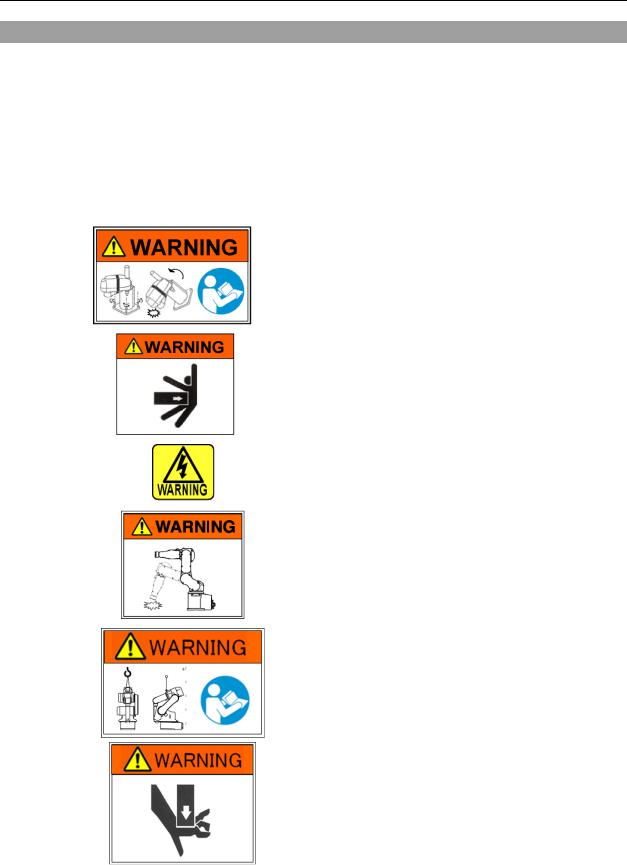
1.7 Labels
The Manipulator has the following warning labels.
The warning labels are attached around the locations where specific dangers exist.
Be sure to comply with descriptions and warnings on the labels to operate and maintain the Manipulator safely.
Do not tear, damage, or remove the warning labels. Use meticulous care when handling those parts or units to which the following warning labels are attached as well as the nearby areas.
Location |
Warning Label |
|
NOTE |
|
|
Before loosening the base mounting screws, hold the arm |
|
|
|
and secure it tightly with a band to prevent hands or |
|
A |
|
fingers from being caught in the Manipulator. |
|
|
|
For transport and install procedures, follow the steps |
|
|
|
described in this manual. |
|
|
|
|
|
|
|
Do not enter the operation area while the Manipulator is |
|
B |
|
moving. |
The robot arm may collide against the operator. |
|
This is extremely hazardous and may result in serious |
||
|
|
||
|
|
safety problems. |
|
|
|
|
|
|
|
Hazardous voltage exists while the Manipulator is ON. |
|
C |
|
To avoid electric shock, do not touch any internal |
|
|
|
electric parts. |
|
|
|
|
|
|
|
When releasing the brakes, be careful of the arm falling |
|
|
|
due to its own weight. |
|
D |
|
This warning label is attached on the Manipulator and |
|
|
optional brake release box. |
||
|
|
||
|
|
|
|
|
|
Only authorized personnel should perform sling work and |
|
|
|
operate a crane and a forklift. When these operations are |
|
E |
|
performed by unauthorized personnel, it is extremely |
|
|
hazardous and may result in serious bodily injury and/or |
||
|
|
severe equipment damage to the robot system. |
|
|
|
|
|
|
|
You may get your hand or fingers caught when bringing |
|
|
|
your hand close to moving parts. |
|
F |
|
|
|
|
|
|
|
VT Rev.6 |
11 |

Setup & Operation |
1. Safety |
|
|
||
|
|
|
|
|
|
|
Location |
|
Warning Label |
NOTE |
|
Signature label
S/N (Serial Number) label
G
Location of labels
C
F
 B D
B D
A
 E
E
C C C
 C
C
|
|
|
|
C |
|
|
|
|
C |
|
|
|
|
|
|
|
|
|
|
||
|
|
|
|
C |
|
|
|
|
|
|
|
|
|
|
|
|
|
|
|
C |
|
|
|
|
|
|
|
|
|
|
|
|
|
|
|
|
|
|
|
|
|
|
|
|
|
|
|
|
|
|
|
|
G |
|
|
|
|
|
|
|
|
|
|
|
|
Protection model |
Standard model, Cleanroom model |
|
||||||||
12 |
VT Rev.6 |

Setup & Operation 2. Specifications
2. Specifications
2.1 Features of VT series Manipulators
The VT series Manipulators are Controller integrated Manipulators. The features of the VT series Manipulators are as follows:
For Device design and tooling
- There is no external Controller
No installation space required for an external Controller.
No design is required for external Controller installation or tooling.
- No robot to Controller external cables
There are no external cables required between the robot and Controller.
For Maintenance
- There are no motor unit batteries for the robot
No longer necessary to connect external devices for battery replacement.
-Easy to replace the Manipulator
2.2Model Number
VT6-A90 1 □ □
Mounting type
□ : Table Top mounting R : Ceiling mounting W : Wall mounting
Environment
S : Standard model
C : Cleanroom model
P : Protection model (IP67)
Brake equipment
1 : Brakes on all joints
Arm length
90 : 920 mm
Payload
6 : 6 kg
For details on the specifications, refer to Setup & Operation: 2.7 Specifications.
VT Rev.6 |
13 |
Setup & Operation 2. Specifications
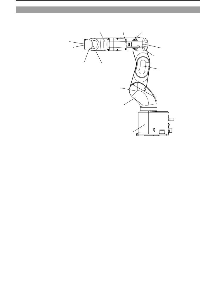
2.3 Part Names
|
|
|
LED Lamp |
|
Arm #4 |
Joint #4 |
(This lamp lights up |
|
while the motors are ON.) |
||
|
|
|
|
Arm #6 |
|
|
|
Joint #6 |
|
|
Arm #3 |
|
|
|
Joint #3 |
Arm #5 |
Joint #5 |
|
|
|
|
Arm #2 |
|
|
|
|
Joint #2
Arm #1
(Lower Arm)
Joint #1 
Base 
NOTE
the Manipulator. (The LED lamp may not be seen depending on the Manipulator’s posture. Be very careful.)
Performing any work with the power ON is extremely hazardous and it may result in electric
shock and/or improper function of the robot system. Make sure to turn OFF the Controller power before the maintenance work.When the LED lamp is lighting or the Controller power is ON, current is being applied to
14 |
VT Rev.6 |
Loading...