


 Loading...
technical manual
TM-U950/TM-U950P
EPSON |
English |
4005789
All rights reserved. No part of this publication may be reproduced, stored in a retrieval system, or transmitted in any form or by any means, mechanical, photocopying, recording, or otherwise, without the prior written permission of Seiko Epson Corporation. No patent liability is assumed with respect to the use of the information contained herein. While every precaution has been taken in the preparation of this book, Seiko Epson Corporation assumes no responsibility for errors or omissions. Neither is any liability assumed for damages resulting from the use of the information contained herein.
Neither Seiko Epson Corporation nor its affiliates shall be liable to the purchaser of this product or third parties for damages, losses, costs, or expenses incurred by purchaser or third parties as a result of: accident, misuse, or abuse of this product or unauthorized modifications, repairs, or alterations to this product, or (excluding the U.S.) failure to strictly comply with Seiko Epson Corporation’s operating and maintenance instructions.
Seiko Epson Corporation shall not be liable against any damages or problems arising from the use of any options or any consumable products other than those designated as Original Epson Products or Epson Approved Products by Seiko Epson Corporation.
EPSON is a registered trademark of Seiko Epson Corporation.
ESC/POS is a trademark of Seiko Epson Corporation.
NOTICE: The contents of this manual are subject to change without notice.
Copyright © 1996 by Seiko Epson Corporation, Nagano, Japan.
EPSON
SEIKO EPSON CORPORATION |
Printed in Japan E96010130-0000SE |

TM-U950/TM-U950P Technical Manual
FCC CLASS A
FCC Compliance Statement
For American Users
This equipment has been tested and found to comply with the limits for a Class A digital device, pursuant to Part 15 of the FCC Rules. These limits are designed to provide reasonable protection against harmful interference when the equipment is operated in a commercial environment.
This equipment generates, uses, and can radiate radio frequency energy and, if not installed and used in accordance with the instruction manual, may cause harmful interference to radio communications. Operation of this equipment in a residential area is likely to cause harmful interference, in which case the user will be required to correct the interference at his own expense.
WARNING
The connection of a non-shielded printer interface cable to this printer will invalidate the FCC Verification of this device and may cause interference levels which exceed the limits established by the FCC for this equipment.
You are cautioned that changes or modifications not expressly approved by the party responsible for compliance could void your authority to operate the equipment.
FOR CANADIAN USERS
This digital apparatus does not exceed the Class A limits for radio noise emissions from digital apparatus as set out in the radio interference regulations of the Canadian Department of Communications.
Le présent appareil numérique n’émet pas de bruits radioélectriques dépassant les limites applicables aux appareils numériques de Class A prescrites dans le règlement sur le brouillage radioélectrique édicté par le Ministère des Communications du Canada.
GEREÄUSCHPEGEL
Gemäß der Dritten Verordrung zum Gerätesicherheitsgecsetz (Maschinenlärminformations- Verordnung-3. GSGV) ist der arbeitsplatzbezogene Geräusch-Emissionswert kleiner als 70 dB(A) (basierend auf ISO 7779).
Rev. A |
i |

Introduction
The TM-U950 printer is an ESC/POS™ compatible high-performance point of sale (POS) printer which can handle receipt, journal, and slip paper. There are two models: the TM-U950 and the TM-U950P. The TM-U950P has a parallel interface. Differences between the two models are noted throughout this manual.
The main features of the TM-U950 and TM-U950P printers are the following:
Usable with a wide range of slip paper types.
Non-protruding interface connectors integrated in the body of the printer.
Bidirectional logic seek for high throughput.
Paper feed pitch of 1/144 inch.
Integrated printer buffer with 32 byte or 2 KB capacity.
Slip paper eject sensor.
ASB (Automatic Status Back) function to send the printer status automatically.
EPSON intelligent module connection (Not available on the TM-U950P).
EPSON customer display series connection (Not available on the TM-U950P).
Optional Magnetic Ink Character Recognition (MICR) reader that enables the printer to perform consecutive reading and processing of MICR characters and printing endorsements (not available for the TM-U950P).
ii |
Rev. A |

TM-U950/TM-U950P Technical Manual
About This Manual
Chapter 1 provides general specifications and hardware configuration information.
Chapter 2 provides general operating principles and printer mechanism configuration information.
Chapter 3 provides handling and maintenance information.
Chapter 4 provides troubleshooting information.
Chapter 5 provides printer disassembly, assembly, and adjustment instructions.
Chapter 6 (Appendix) provides circuit board and exploded diagrams.
Notes and Cautions
Note:
Notes have important information and useful tips on the operation of your printer.
 CAUTION:
Cautions must be observed to avoid damage to your equipment.
Rev. A |
iii |
 Service Manual")
Revision Sheet
Revision |
Page |
Altered Item and Contents |
Rev. A
iv |
Rev. A |

TM-U950/TM-U950P Technical Manual
Contents
Chapter 1 Features and General Specifications
Features ...................................................................................................................................................................................... |
1-1 |
General Specifications .............................................................................................................................................................. |
1-3 |
Printing Specifications ...................................................................................................................................................... |
1-3 |
Character Specifications .................................................................................................................................................. |
1-4 |
Paper Specifications ......................................................................................................................................................... |
1-5 |
Paper Roll Feed Mechanism ............................................................................................................................................ |
1-9 |
Journal Paper Take-up Mechanism ................................................................................................................................ |
1-9 |
Auto-cutter ........................................................................................................................................................................ |
1-9 |
Electrical Specifications .................................................................................................................................................... |
1-9 |
Stamp .................................................................................................................................................................................. |
1-10 |
Ink Ribbon ......................................................................................................................................................................... |
1-10 |
Dimensions, Weight, Finish ............................................................................................................................................ |
1-11 |
Environmental Specifications ......................................................................................................................................... |
1-11 |
Reliability ........................................................................................................................................................................... |
1-12 |
Hardware Configuration ......................................................................................................................................................... |
1-13 |
Main Unit Configuration ................................................................................................................................................. |
1-13 |
Main Unit Specifications .................................................................................................................................................. |
1-14 |
Connectors ......................................................................................................................................................................... |
1-17 |
Interface .............................................................................................................................................................................. |
1-19 |
Switches and Buttons ....................................................................................................................................................... |
1-27 |
Functions .................................................................................................................................................................................... |
1-31 |
Error Processing ................................................................................................................................................................ |
1-31 |
Self-test ............................................................................................................................................................................... |
1-32 |
Hexadecimal Dumping .................................................................................................................................................... |
1-32 |
Printing Operation ............................................................................................................................................................ |
1-33 |
Options ....................................................................................................................................................................................... |
1-34 |
AC Adapter (PS-150) ........................................................................................................................................................ |
1-34 |
Journal Lock ...................................................................................................................................................................... |
1-34 |
Chapter 2 Mechanism Configuration and Operating Principles |
|
|
|
Printer Mechanism Components ............................................................................................................................................ |
2-1 |
Printer Mechanism Operating Principles .............................................................................................................................. |
2-2 |
Printing Assembly ............................................................................................................................................................. |
2-2 |
Sensor Assemblies ............................................................................................................................................................. |
2-4 |
Paper Feed Assembly ....................................................................................................................................................... |
2-9 |
Slip Paper Assembly ........................................................................................................................................................ |
2-12 |
MICR Reader Assembly (for printers with a MICR reader) (not available for the TM-U950P) ........................... |
2-16 |
Ribbon Feed Assembly .................................................................................................................................................... |
2-18 |
Stamp Assembly (for printers with a stamp assembly) .............................................................................................. |
2-19 |
Auto-cutter Assembly ...................................................................................................................................................... |
2-20 |
Paper Roll Take-up Assembly ........................................................................................................................................ |
2-23 |
Electrical Circuitry Operating Principles .............................................................................................................................. |
2-25 |
Hardware Configuration ................................................................................................................................................. |
2-25 |
Main Board Operating Principle .................................................................................................................................... |
2-30 |
MICR Board Operating Principle (on printers with a MICR reader) (not available for the TM-U950P) ............ |
2-49 |
Rev. A |
v |

Chapter 3 Handling and Maintenance
Handling ..................................................................................................................................................................................... |
3-1 |
Handling Precautions ....................................................................................................................................................... |
3-1 |
Loading the Paper Rolls ................................................................................................................................................... |
3-2 |
Removing the Paper Rolls ................................................................................................................................................ |
3-4 |
Inserting Slip Paper and Printing on Slip Paper ........................................................................................................... |
3-5 |
Printing on Personal Checks (only on printers with a MICR reader) (not available for the TM-U950P) ............ |
3-6 |
Installing and Removing the Ribbon Cassette .............................................................................................................. |
3-8 |
Inserting the Stamp Set ..................................................................................................................................................... |
3-9 |
Mounting the Power Switch Cover ................................................................................................................................ |
3-10 |
Journal Lock Key Handling ............................................................................................................................................. |
3-10 |
Removing the Jammed Paper .......................................................................................................................................... |
3-10 |
Maintenance ............................................................................................................................................................................... |
3-13 |
Periodic Checks ................................................................................................................................................................. |
3-13 |
Cleaning .............................................................................................................................................................................. |
3-13 |
Lubrication ......................................................................................................................................................................... |
3-14 |
Tool List .............................................................................................................................................................................. |
3-17 |
Measuring Equipment List .............................................................................................................................................. |
3-18 |
Lubricant List ..................................................................................................................................................................... |
3-18 |
Chapter 4 Troubleshooting |
|
|
|
Troubleshooting ........................................................................................................................................................................ |
4-1 |
Self-test ................................................................................................................................................................................ |
4-1 |
Troubleshooting Flowchart .............................................................................................................................................. |
4-4 |
Troubleshooting Tables .................................................................................................................................................... |
4-12 |
Major Part Replacements ......................................................................................................................................................... |
4-23 |
Fuse replacement ............................................................................................................................................................... |
4-23 |
Print Head Unit Replacement ......................................................................................................................................... |
4-23 |
Cutter Blade Replacement ................................................................................................................................................ |
4-23 |
Error Types And Countermeasures ........................................................................................................................................ |
4-24 |
Chapter 5 Disassembly, Assembly, and Adjustment |
|
|
|
Small Part Specifications .......................................................................................................................................................... |
5-1 |
Actual Size E-type Retaining Rings ................................................................................................................................ |
5-1 |
Disassembly ............................................................................................................................................................................... |
5-2 |
Replacing the Print Head Unit ........................................................................................................................................ |
5-3 |
Replacing the Cutter Blade .............................................................................................................................................. |
5-5 |
Printer Mechanism Unit Assembly ......................................................................................................................................... |
5-6 |
Sub-assembly A: Detector-Paper Assembly................................................................................................................... |
5-7 |
Sub-assembly B: Paper Guide-Upper Unit Assembly ................................................................................................. |
5-8 |
Sub-assembly C: Paper Guide-Lower Unit Assembly.................................................................................................. |
5-10 |
Sub-assembly D: Cutter Motor Mount Plate Assembly ............................................................................................... |
5-12 |
Sub-assembly E: Roller-Paper Hold Assembly.............................................................................................................. |
5-12 |
Sub-assembly F: Cutter Frame Assembly....................................................................................................................... |
5-13 |
Sub-assembly G: Detector-Slip Ejection Assembly ....................................................................................................... |
5-13 |
Sub-assembly H: Auto-cutter Unit Assembly ............................................................................................................... |
5-14 |
Sub-assembly I: Pulley Base-Carriage Transmission Assembly ................................................................................. |
5-17 |
Sub-assembly J: Carriage-Head Assembly .................................................................................................................... |
5-17 |
Sub-assembly K: Assembling the MICR Head Holder Assembly (for printers with a MICR reader) ................. |
5-18 |
Sub-assembly L-(1): Frame-Carriage Unit Assembly (for printers without a MICR reader) ................................. |
5-22 |
Sub-assembly L-(2): Frame Carriage Unit Assembly (for printers with a MICR reader)........................................ |
5-27 |
Sub-assembly M: Frame-Inner Assembly....................................................................................................................... |
5-35 |
Sub-assembly N: Detector-Slip Insertion Assembly ..................................................................................................... |
5-36 |
Sub-assembly O: Solenoid J/S Changeover Assembly................................................................................................. |
5-36 |
Sub-assembly P: Paper Guide-Slip-Lower Assembly ................................................................................................... |
5-37 |
vi |
Rev. A |

TM-U950/TM-U950P Technical Manual
Sub-assembly Q: Frame-Paper Take-up Assembly ...................................................................................................... |
5-38 |
Sub-assembly R: Assembling the motor-paper guide-J assembly (for printers with a MICR reader).................. |
5-39 |
Main Assembly (Part 1) ................................................................................................................................................... |
5-40 |
Adjustments ...................................................................................................................................................................... |
5-53 |
Main Assembly (Part 2) ................................................................................................................................................... |
5-59 |
Whole Unit Assembly .............................................................................................................................................................. |
5-65 |
Sub-assembly A: N.E. Detector-J Assembly and N.E. Detector-R Assembly ........................................................... |
5-65 |
Sub-assembly B: Holder-Switch Circuit Board Assembly .......................................................................................... |
5-67 |
Sub-assembly C: Journal Lock and Cover-Paper Take-up Assembly (Option) ...................................................... |
5-68 |
Sub-assembly D: Cover Paper Take-up ......................................................................................................................... |
5-69 |
Main Assembly ......................................................................................................................................................................... |
5-70 |
Main Assembly 1: Main Circuit Board, P-ROM, and Plate-Main Mounting ........................................................... |
5-70 |
Main Assembly 2: FFC, Power Cable, and Plate-Circuit Board Attachment ........................................................... |
5-71 |
Main Assembly 3: Printer Mechanism Assembly Attachment on Plate-Main ........................................................ |
5-72 |
Main Assembly 4: N.E. Detector-R and -J Assemblies Attachment .......................................................................... |
5-73 |
Main Assembly 5: Printer Mechanism Assembly Attachment on Case-Lower Assembly .................................... |
5-75 |
Main Assembly 6: Case-Upper Assembly Mounting .................................................................................................. |
5-76 |
Main Assembly 7: Cover-Face and Cover-Main Assembly Attachment .................................................................. |
5-77 |
Main Assembly 8: Cover-ROM Attachment ................................................................................................................. |
5-78 |
Adjustments .............................................................................................................................................................................. |
5-79 |
Adjustment G: Adjusting the Paper Roll Near-end Detector Location .................................................................... |
5-79 |
Adjustment H: Detector-Slip Insertion Assembly Threshold Value Adjustment.................................................... |
5-81 |
Adjustment I: MICR mechanism check.......................................................................................................................... |
5-83 |
Chapter 6 Appendix |
|
|
|
Electrical Circuit Drawings ...................................................................................................................................................... |
6-1 |
Circuit 1.............................................................................................................................................................................. |
6-2 |
Circuit 2.............................................................................................................................................................................. |
6-3 |
Circuit 3.............................................................................................................................................................................. |
6-4 |
Circuit 4.............................................................................................................................................................................. |
6-5 |
Circuit 5.............................................................................................................................................................................. |
6-6 |
Circuit 6.............................................................................................................................................................................. |
6-7 |
Circuit 7.............................................................................................................................................................................. |
6-7 |
Circuit 8.............................................................................................................................................................................. |
6-8 |
Main Unit Circuit Drawing for TM-U950..................................................................................................................... |
6-9 |
Main Unit Circuit Drawing for TM-U950P .................................................................................................................. |
6-10 |
MICR Board (for printers with a MICR reader) (Not available for the TM-U950P) .............................................. |
6-11 |
Parallel Interface Circuit Board Diagram ..................................................................................................................... |
6-12 |
Main Circuit Board Parts Layout for TM-U950 ........................................................................................................... |
6-13 |
Main Circuit Board Parts Layout for TM-U950P......................................................................................................... |
6-14 |
Parallel Interace Circuit Board Parts Layout................................................................................................................ |
6-15 |
Overall Exploded Diagrams ........................................................................................................................................... |
6-16 |
Lubrication Points Diagram for Printers Without a MICR Reader (1/3) ................................................................ |
6-26 |
Lubrication Points Diagram for Printers Without a MICR Reader (2/3) ................................................................ |
6-27 |
Lubrication Points Diagram for Printers Without a MICR Reader (3/3) ................................................................ |
6-28 |
Lubrication Points Diagram for Printers With a MICR Reader (1/4) ...................................................................... |
6-29 |
Lubrication Points Diagram for Printers With a MICR Reader (2/4) ...................................................................... |
6-30 |
Lubrication Points Diagram for Printers With a MICR Reader (3/4) ...................................................................... |
6-31 |
Lubrication Points Diagram for Printers With a MICR Reader (4/4) ...................................................................... |
6-32 |
Rev. A |
vii |
TM-U950/U950P Technical Manual
Chapter 1
Features and General Specifications
Features
The TM-U950 printer is an ESC/POS™ compatible high-performance point of sale (POS) printer which can handle receipt, journal, and slip paper. There are two models: the TM-U950 and the TM-U950P. The TM-U950P has a parallel interface. Differences between the two models are noted throughout this manual.
The main features of the TM-U950 and TM-U950P printers are the following:
Usable with a wide range of slip paper types.
Non-protruding interface connectors integrated in the body of the printer.
Bidirectional logic seek for high throughput.
Paper feed pitch of 1/144 inch.
Integrated printer buffer with 32 byte or 2 KB capacity.
Slip paper eject sensor.
ASB (Automatic Status Back) function to send the printer status automatically.
EPSON intelligent module connection (Not available on the TM-U950P).
EPSON customer display series connection (Not available on the TM-U950P).
Optional Magnetic Ink Character Recognition (MICR) reader that enables the printer to perform consecutive reading and processing of MICR characters and printing endorsements (not available for the TM-U950P).
Rev. A |
Features and General Specifications 1-1 |

Figure 1-1. TM-U950 Appearance
1-2 Features and General Specifications |
Rev. A |

TM-U950/U950P Technical Manual
General Specifications
Printing Specifications
Operation principle
Serial impact dot-matrix printer
Print head wire layout
Serial 9-pin
Dot pitch
0.353 mm (1/72”)
Dot wire diameter
0.29 mm (.01”)
Figure 1-2. Dot Configuration
Print direction
Bidirectional logic seek
Print width (printable area)
Paper roll: 61.1 mm (2.41”)
Slip paper: 135.6 mm (5.34”)
Paper feed pitch
4.233 mm (1/6”) (default setting) adjustable (by commands) in 1/144-inch steps
Paper feed principle
Friction feed
Paper feed rate
Approx. 3.4 IPS (continuous paper); 60.3 ms per line (1/6-inch paper feed)
Rev. A |
Features and General Specifications 1-3 |

Printing format
See CPI in Table 1-2.
Character spacing
See Table 1-2.
Total dot count
70 mm paper roll (2.76”): |
180 dots (360 positions) per line |
Slip paper: |
400 dots (800 positions) per line |
Printing speed |
|
See Table 1-2. |
|
As shown in the table below, the TM-U950 has three printing modes, which differ in printing speed and head power time (impact).
Table 1-1. Printing Operation Mode
Operation mode |
Printing speed |
Head power time (impact) |
|
|
|
Standard |
High |
Standard |
|
|
|
Copy |
Low |
Copy |
|
|
|
Low-speed |
Low |
Standard |
|
|
|
Character Specifications
Character set
Alphanumeric: |
95 |
International: |
32 |
Extended graphics: |
128 x 8 pages |
Character matrix
(Alphanumeric, international, extended graphics) 7 x 9 (spacing: 2 half-dots)
0 x 9 (spacing: 3 half-dots)
Larger spacing can be set by using ESC SP.
Table 1-2. CPI, CPS, CPL, Character Size
CG Mode |
|
|
Characters Per Second |
|
|
|
||
(Horizontal |
Character |
Characters |
(CPS) (Carriage moving |
Characters Per Line (CPL) |
Character Size |
|||
dots x |
Spacing |
Per Inch |
speed) |
|
|
|
||
|
|
|
Width x Height |
|||||
vertical |
(half dots) |
(CPI) |
|
|
|
|
||
High speed |
Low speed |
Paper roll |
Slip paper |
|
||||
dots) |
|
|
|
|||||
|
|
|
|
|
|
|
|
|
9 x 9 |
3 dots |
12.5 |
233 |
200 |
30 |
66 |
1.6 mm x 3.1 mm |
|
(0.6” x .12”) |
||||||||
|
|
|
|
|
|
|
||
|
|
|
|
|
|
|
|
|
7 x 9 |
2 dots |
16.7 |
311 |
267 |
40 |
88 |
1.3 mm x 3.1 mm |
|
(0.5” x .12”) |
||||||||
|
|
|
|
|
|
|
||
|
|
|
|
|
|
|
|
|
1-4 Features and General Specifications |
Rev. A |

TM-U950/U950P Technical Manual
Figure 1-3. Character Size
Paper Specifications
Paper type
Paper roll
Wood-free paper (single layer only)
Slip paper
Plain paper Carbon copy paper
Pressure-sensitive paper
Paper dimensions
Paper roll |
|
Paper width: |
69.5 + 0.5 mm (2.74 + 0.02”) |
Maximum diameter: |
83 mm (3.27”) |
Paper thickness: |
0.06 to 0.09 mm (.002 to .004”) |
Paper weight: |
52.3 to 64 g/m 2 (13.9 to 171 lbs) |
|
(45 to 55 kg/1000 sheets; 788 x 1091 mm) |
|
(20.41 to 24.94 lbs/1000 sheets; 31.02 x 42.95”) |
Core diameter: |
10 mm (0.39”) or more |
Rev. A |
Features and General Specifications 1-5 |

Slip paper |
|
Dimensions: |
70 x 70 to 210 x 297 mm (W x H) |
|
(2.76 x 2.76 to 8.27 x 11.69”) |
Thickness: |
0.09 to 0.36 mm (.004 to .014”) |
Temperature and copying capability
As copying capability is influenced by the ambient temperature, printing must be performed under the conditions described in Table 1-3.
Table 1-3. Relationship Between Ambient Temperature and Number of Copies
Number of Copies |
Ambient Temperature |
|
|
Original + 4 copies |
approx. 20° to 40°C (68° to 104°F) |
|
|
Original + 1 to 3 copies |
5° to 40°C (41° to 104°F) |
|
|
Paper thickness and copying capability
Plain paper (single sheet): |
0.09 to 0.2 mm |
|
(.0035 to .0079”) |
Carbon copy paper (original + 4 copies)
Backing paper |
0.06 to 0.15 mm |
(.002 to .006”) |
Copy paper and original paper |
0.04 to 0.07 mm |
(.0016 to .003”) |
Carbon paper |
Approx. 0.035 mm (.001”) |
|
Total thickness |
0.30 mm (.012”) or less (1 to 1 + 3) |
|
0.36mm (.014”) or less (1 + 4)
Pressure-sensitive paper (original + 4 copies)
Backing paper |
0.06 to 0.15 mm (.002 to .006”) |
Copy paper and original paper |
0.06 to 0.075 mm (.002 to .003”) |
Total thickness |
0.24 mm (.009”) or less (1 to 1 + 3) |
|
0.30 mm (.012”) or less (1 + 4) |
Note:
When using multi-ply paper that consists of an original and three copies, be sure to print with a 9 x 9 font. If a 7 x 9 font is used, some characters on some of the copies may not be readable.
Check paper (only when the printer is used with the MICR reader)
Paper type: |
Normal paper |
Total thickness: |
0.09 to 0.2 mm (.0035 to .0079”) |
1-6 Features and General Specifications |
Rev. A |

|
TM-U950/U950P Technical Manual |
Size: |
68 to 102 mm x 152 to 210 mm |
|
(2.68 to 4.02” x 2.98 to 8.27”) |
Weight: |
70 to 90 kg paper |
Notes on setting the print operation mode
The GS E command sets print mode (printing speed and print head energizing time).
When the power is turned on, normal mode is selected as the default. The printer automatically switches from normal mode to copy mode when slip is selected by ESC c 0.
Notes on slip paper
The slip paper must be flat, without curls or wrinkles, especially at the top edges. Otherwise, the paper may rub against the ribbon and become dirty.
There must be no glue on the bottom edge of slip paper. It is desirable for the glue to be on the top edge. Choose slip paper carefully when the glue is on the right or left edge, since paper feeding and insertion are affected by gluing conditions (e.g., glue quality, method, and length) and glue location (see Figure 1-4). Be especially careful when slip paper is wide and has the glue on the right or left edge, since meandering may occur.
Since the slip insertion sensor uses a photo sensor, paper that has holes at the sensor position, or is translucent, must not be used (see Figure 1-5).
Since the slip ejection sensor uses a reflective photo sensor, paper that has holes or dark portions with low reflection (less than 40% reflection) at the sensor position must not be used (see Figure 1-6).
Be sure to perform slip printing with a paper roll loaded to avoid incorrect paper feeding due to paper jams.
Use thinner paper (N30 or equivalent) between the top and bottom sheets of multi-ply paper. If thick paper is used, the copy capability is lowered.
Notes on using personal check paper (for printers with an MICR reader)
The personal checks must be flat, without curls, folds, or wrinkles (especially at the edges). Otherwise, the check may rub against the ribbon and become ink-stained.
Figure 1-4. Slip Paper Glued Area
Rev. A |
Features and General Specifications 1-7 |

Figure 1-5. Slip Insertion Sensor Position
Figure 1-6. Paper Holes and Low Reflection Prohibited Area
Print area
Paper roll
Figure 1-7. Paper Roll Print Area
1-8 Features and General Specifications |
Rev. A |

TM-U950/U950P Technical Manual
Slip paper
Figure 1-8. Slip Paper Print Area
*Note
When the printer uses an MICR reader, this width is 5.0mm (0.20”).
Paper Roll Feed Mechanism
Feed principle
Drop-in loading
Paper roll near-end detection
Separate sensors for receipt paper and journal paper.
Journal Paper Take-up Mechanism
Automatic take-up by journal paper feed motor.
Auto-cutter
Auto-cutter is installed only on receipt side, for full and partial cuts.
Electrical Specifications
Printer operation voltage (using supplied AC adapter)
+24 V DC ± 10%
Ripple voltage: 300 mVpp or less (only when the printer is used with the MICR reader)
Current consumption
During printing
Average approx. 1.8 A
(R/J, α - N, 40-character printing) Peak approx. 8 A
During slip paper feed to printing position: Average approx. 0.3 A (for approx. 1.4s)
Rev. A |
Features and General Specifications 1-9 |

During standby Average approx. 0.3 A
Operating MICR reader
(when the printer used with the MICR reader) Mean - approximately 2.3 A
(Approximately 1.4 seconds)
Stamp
Stamp mechanism is available as a factory option for the receipt side.
Recommended stamp: |
Fuji Copian CSP-2042C |
Recommended ink: |
Fuji Copian Super Ink |
Print area: |
42 x 20 mm (1.65 x 0.79”) |
|
(W x H) |
Dimensions of stamp pad: See Figure 1-9.
Dimensions of stamp set: See Figure 1-10.
[Unit: mm]
|
|
|
Figure 1-9. Stamp Pad Dimensions |
Figure 1-10. Stamp Set Dimensions |
|
Ink Ribbon
Ribbon cassette
ERC-31 (P)
ERC-31 (B)
Color
Purple: ERC-31 (P)
Black: ERC-31 (B)
Ribbon life (18 dots per character)
Figure 1-11. Ribbon Cassette Dimensions
7,000,000 characters
1-10 Features and General Specifications |
Rev. A |
TM-U950/U950P Technical Manual
Dimensions, Weight, Finish
Dimensions
251 x 298 x 194.5 mm (9.88 x 11.73 x 7.66”) (W x D x H)
Weight
Approx. 5.6 kg (12.3 lbs)
Color
EPSON Standard Gray
Environmental Specifications
Temperature
Operation: |
5° to 40°C (41° to 104°F) |
|
Storage: |
-10° to +50°C (14° to 122°F) (except ribbon) |
|
Humidity |
|
|
Operation: |
30 to 80% (non-condensing; limit above 30°C: 30°C, 80%) |
|
Storage: |
30 to 90% (non-condensing; except ribbon) |
|
Vibration resistance (in standard EPSON packing) |
||
Frequency: |
5 to 55 Hz |
|
Acceleration: |
2 G |
|
Sweep: |
5 minutes (one way) |
|
Time: |
1 h |
|
Directions: |
X, Y, Z |
|
No visible external or internal problems or operation failure after the above vibration test. |
||
Shock resistance (in standard EPSON packing) |
||
|
With packing |
|
|
Drop height: |
50 cm (19.69”) |
|
Angle: |
1 angle, 3 surfaces, 6 sides |
No visible external or internal problems or operation failure after the above drop test. |
||
|
Without packing |
|
|
Drop height: |
5 cm (1.97”) |
|
Angle: |
4 sides, one-point support |
No damage when dropped while printer is off.
Rev. A |
Features and General Specifications 1-11 |

Noise
63 dB (operating, measured in ANSI bystander position; printing on receipt and journal paper roll)
Reliability
Mechanics
MCBF |
5,000,000 lines (auto-cutter and stamp once every 15 lines) |
Life expectancy |
7,500,000 lines (The printer’s life is considered over when the |
|
printer cannot function due to worn-out main parts such as |
|
motor, solenoids, frames, and shafts.) |
Life expectancy of print head |
150,000,000 characters (average 2 dot/wire/1 character) |
MICR reader mechanism (only when the printer is used with the MICR reader):
MCBF: |
160,000 passes |
Life: |
240,000 passes |
|
1 pass: reading characters to printing endorsements on a |
|
U.S. personal check (152 mm (5.98”) long) |
|
The MICR reader is defined to have reached the end of its |
|
life when it cannot function properly because of wearing out |
|
of the main parts (magnetic head, head holding roller, etc). |
Certifications |
|
Japan: |
EMI: VCCI Class 1 |
North America: |
EMI: FCC Class 1 |
|
Safety standards: UL1950-2TH-D3 |
|
C-UL |
Europe: |
CE marking (printer with MICR reader under application) |
|
EN55022 |
|
EN50082-1 |
|
EN45501 (except when connected to IM) |
|
Safety standard: TÜV |
1-12 Features and General Specifications |
Rev. A |

TM-U950/U950P Technical Manual
Hardware Configuration
Main Unit Configuration
Printer mechanism
Figure 1-12. TM-U950 Printer Mechanism Main Unit Configuration
Electrical circuit and unit on cases
Figure 1-13. TM-U950 Electrical Circuit and Unit on Cases Main Unit Configuration
Rev. A |
Features and General Specifications 1-13 |

Main Unit Specifications
Paper feed motors
Receipt and journal paper feeding is performed by dedicated feed motors. Slip paper feeding is performed by using the journal paper feed motor and a journal/slip switching solenoid.
Motor type
4-phase, 48-pole PM type stepping motor
Drive voltage
24 V DC + 10% (including voltage drop caused by drive transistor)
Winding resistance
Journal paper feed motor |
35 Ω ± 7% at 25°C (77°F), per phase |
Receipt paper feed motor: |
42 Ω ± 7% at 25°C (77°F), per phase |
Current consumption (per motor) |
|
Journal paper feed motor |
|
Peak current: |
1.94A in worst case |
Average current: |
615 mA at rated speed; 25°C (77°F), 24 V DC, 500 pps |
|
930 mA max. in worst case |
Hold current |
92.5+42.5 mA per phase at normal hold, 25°C (77°F) |
Receipt paper feed motor |
|
Peak current: |
1.5 A in worst case |
Average current: |
510 mA at rated speed; 25°C (77°F), 24 V DC, 500 pps |
|
770 mA max. in worst case |
Hold current: |
Approx. 130 ± 50 mA per phase at normal hold, 25°C (77°F) |
Drive frequency
500 pps (minimum pulse interval 2.00 ms)
Drive principle
Constant voltage drive, 2-2 phase induction
Carriage motor
Motor type
4-phase, 48-pole PM type stepping motor
1-14 Features and General Specifications |
Rev. A |

TM-U950/U950P Technical Manual
Drive voltage
24 V DC ± 10% (including voltage drop caused by drive transistor)
Winding resistance
9 Ω ± 7% at 25°C (77°F), per phase
Current consumption (per motor)
Peak current: |
1.5 A in worst case |
Average current: |
550 mA at rated speed |
Hold current: |
150 mA± 8% per phase |
Drive frequency |
|
Standard mode: |
1400 pps (pulse interval 714 μs) |
Copy mode: |
1200 pps (pulse interval 834 μs) |
Drive principle
Constant-current chopper drive, 2-2 phase induction
Carriage feed pitch
0.3386 mm (1/75”) per pulse
Print head unit (print solenoids)
Number of solenoids: |
9 |
Drive voltage: |
24 V DC ± 10% (including voltage drop caused by drive |
|
transistor) |
DC resistance: |
6.65 Ω ± 4% at 25°C (77°F) |
Near-end sensors (journal, receipt)
A sensor is provided for the receipt and journal paper roll respectively. The sensors check the diameter of each roll and activate the near-end alarm when the diameter falls below a userdetermined value.
Sensor type: |
Microswitch |
Voltage: |
5 V DC ± 5% |
Output level: |
Low when near-end is detected |
Paper roll sensors (journal, receipt) (*)
A sensor is provided in the paper path (receipt and journal side, respectively) of the printer mechanism. These sensors check for the presence of paper, and accordingly control loading of the paper roll.
Sensor type: |
Microswitch |
Switch rating: |
10 to 100 mA, 5 V DC (resistive load) |
Contact condition: |
On when paper is present |
(*)If the paper roll sensor detects the “no paper” condition while the cover is open, semiautomatic loading can be performed by inserting the paper roll into the paper path.
Rev. A |
Features and General Specifications 1-15 |

Slip paper insert sensor
This sensor is located in the slip paper loading path to detect the insertion of slip paper.
Sensor type: |
Photosensor |
Voltage: |
5 V DC ± 5% |
Input current: |
Approx. 20 mA |
Output level: |
High when slip paper is detected |
Slip paper eject sensor
This sensor is located in the slip paper eject path to detect ejection of slip paper. If ejection is not detected, the printer does not proceed to the next step.
Sensor type: |
Photosensor |
Voltage: |
5 V DC ± 5% |
Cover open sensor (*)
This sensor detects the condition of the printer cover. If the cover is open, the printer automatically goes off-line after the current printing operation and the carriage returns to the home position at slow speed. The printer goes back on-line when the cover is closed.
Sensor type: |
Photosensor |
Voltage: |
5 V DC ± 5% |
Input current: |
10 mA |
Output level: |
High when cover open is detected |
(*)If the paper roll sensor detects the “no paper” condition while the cover is open, semiautomatic loading can be performed by inserting the paper roll into the paper path.
Auto-cutter sensor
Sensor type: |
Mechanical contact sensor |
Voltage: |
5 V DC ± 5% |
Current rating: |
0.1 to 0.5 mA |
Home position sensor
This sensor detects the carriage initial position (on the receipt paper side) and the carriage abnormal operation.
Sensor type: |
Photosensor |
Voltage: |
5 V DC ± 5% |
Output level: |
High when the carriage home position is detected |
Carriage sensor
This sensor outputs signal synchronized with the carriage operation, and detects whether the carriage operation is abnormal.
Sensor type: |
Photosensor |
Voltage: |
5 V DC ± 5% |
Output level: |
High when sensor plate is detected |
1-16 Features and General Specifications |
Rev. A |
TM-U950/U950P Technical Manual
MICR Reader (when the printer is used with the MICR reader) (Not available for the TM-U950P)
Available fonts: |
E-13B, CMC7 |
|
|
Recognition rating: |
98% or more (at 25°C) |
|
|
Recognition rating is defined as follows: |
|
||
|
Total number of checks - (number of sheets misread |
|
|
Recognition rating (%) = |
and those not identified) |
× 100 |
|
|
|
||
|
|
||
Total number of checks
Check paper used for test is EPSON standard check paper. Checks must be flat, without curls, folds, or wrinkles.
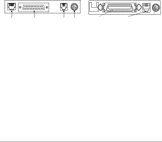
Connectors
All connectors are located on the rear panel of the printer. (Refer to Figure 1-1.)
Connector panels
|
14 |
|
25 |
|
|
2 |
|
|
1 |
8 |
|
1 |
6 |
|
|
|
|
|
|
|
|
|
||||
|
|
|
|
|
3 |
1 |
|
|
|
1 |
|
13 |
|
|
|
|
|
Customer display |
Interface |
|
|
|
Interface connector |
Drawer kickout |
Power connector |
|
Drawer kick- |
Power |
connector |
|
|||||
(DM-D) connector |
connector |
out connector |
connector |
|
|
|||
TM-U950 |
TM-U950P |
Figure 1-14. Rear Panel Connectors
Interface
See the Interface section in this chapter.
Power supply connector
This connector is for the AC adapter.
Connector type: |
TCS7960-53-2010 (Hoshiden) or equivalent |
|
Table 1-4. Power Supply Pin Assignment |
||
|
|
|
Pin number |
Function |
|
|
|
|
1 |
24 VDC |
|
|
|
|
2 |
Signal ground |
|
|
|
|
3 |
NC |
|
|
|
|
Shell |
Frame ground |
|
|
|
|
Note:
Be sure to ground the printer via the frame ground terminal on the metal strip on the rear panel.
Rev. A Features and General Specifications 1-17

Drawer kick-out connector (modular connector)
Pulse specified by ESC p command is output to this connector. The host can confirm the status of the input signal by using the DLE EOT, ESC u, GR r, or GS a (ASB) commands.
Connector type:
Printer side |
52065-6615 (Molex) or equivalent |
|||
User side |
6-position 6-contact (RJ12 telephone jack) |
|||
Table 1-5. Drawer Kick-out Connector Pin Assignment |
||||
|
|
|
|
|
Pin number |
Signal name |
|
I/O |
|
|
|
|
|
|
1 |
Frame ground |
|
— |
|
|
|
|
|
|
2 |
Drawer kick-out drive signal 1 (*1) |
O |
|
|
|
|
|
|
|
3 |
Drawer open/close signal (*2) |
I |
|
|
|
|
|
|
|
4 |
+ 24 V |
|
— |
|
|
|
|
|
|
5 |
Drawer kick-out drive signal 2 (*1) |
O |
|
|
|
|
|
|
|
6 |
Signal ground |
|
— |
|
|
|
|
|
|
(*1) Drawer kick-out drive signal
The signal specified by the ESC p command is output from pins 2 and 5 of the connector.
Output voltage: |
|
|
Approx. 24 V |
||||||
Output current: |
|
|
1 A max. |
||||||
Output waveform: |
|
|
The waveform of the signal at pins 2 and 5 is shown in |
||||||
|
|
|
|
|
|
|
Figure 1-15. (The ON time n1 and OFF time n2 are |
||
|
|
|
|
|
|
|
determined by the ESC p command.) |
||
|
|
|
|
|
|
|
|
|
|
|
|
|
|
|
|
|
|
|
|
|
|
|
|
|
|
|
|
|
|
|
|
|
|
|
|
|
|
|
|
|
|
|
|
|
|
|
|
|
|
n1 x 10ms n2 x 10ms
Figure 1-15. Drawer Kick-out Drive Signal Timing
(*2) Drawer open/close signal
The host computer can check the drawer open/close status with the DLE EOT, ESC u, GR r, or GS a (ASB) commands.
Input signal level (connector pin 3)
Low = 0 to 0.8 V
High = 2 to 5 V
1-18 Features and General Specifications |
Rev. A |

TM-U950/U950P Technical Manual
Notes
Use a shielded cable for the drawer connection.
It is not possible to drive two drawers at the same time.
Use a solenoid rated for at least 24 Ω as the drawer kick-out solenoid. Otherwise, excessive current may damage the solenoid.
The drawer must be powered from the printer (connector pin 4).
Do not drive the drawer continuously.
Customer display connector (not supported on the TM-U950P)
This connector is for Epson customer display (DM-D series). Do not connect other customer displays.
Connector type: |
|
Receptacle 52065-8845 (Molex) or equivalent |
|
Table 1-6. Customer Display Connector Pin Assignment |
|||
|
|
|
|
Pin number |
Signal name |
I/O |
|
|
|
|
|
1 |
Frame ground |
— |
|
|
|
|
|
2 |
NC |
— |
|
|
|
|
|
3 |
TXD |
O |
|
|
|
|
|
4 |
DTR |
O |
|
|
|
|
|
5 |
DSR |
I |
|
|
|
|
|
6 |
Signal ground |
— |
|
|
|
|
|
7 |
+24V DC |
— |
|
|
|
|
|
8 |
Power ground |
— |
|
|
|
|
|
Interface
Serial interface
Data transfer principle |
Serial (RS-232 interface) |
Synchronization |
Asynchronous |
Handshake (*) |
DTR/DSR or XON/XOFF |
Signal level |
|
MARK: -3 to -15 V (logical “1”/OFF) SPACE: +3 to +15 V (logical “0”/ON)
(Voltage measured at connector, referenced to SG)
Baud rate (*) |
1200, 2400, 4800, 9600 bps |
Word length (*) |
7 or 8 bit |
Rev. A |
Features and General Specifications 1-19 |

Parity (*) |
None, even, odd |
Number of stop bits |
1 or more |
Connector type |
D-SUB 25 female or equivalent |
(*)Can be set with DIP switches on the bottom of the unit (See Tables 1-9 and 1-10.)
On-line/off-line switching
This printer has no on-line/off-line switch. It automatically goes off-line in the following cases:
During self-test.
When the cover is open.
When the paper feed button (receipt or journal/slip) is used to advance the paper.
When printing has stopped due to no paper (“no paper” condition selected with ESC c 4).
During the interval between power-on (including reset using the interface) and the end of the initialization sequence, until data can be received.
When an error has occurred
During the macro execution switch waiting status.
Table 1-7. Interface Connector Specifications and Functions
Pin number |
Signal name |
I/O |
Function |
|
|
|
|
1 |
FG |
— |
Frame ground |
|
|
|
|
2 |
TXD |
O |
Transmit data |
|
|
|
|
3 |
RXD |
I |
Receive data |
|
|
|
|
|
|
|
DIP SW1-6 off: Same as DTR signal (Pin20) |
4 |
RTS |
O |
DIP SW1-6 on: Logical product of DTR signals of DM-D and TM (if both are |
|
|
|
SPACE, the printer can receive data. |
|
|
|
|
|
|
|
Indicates whether the host is ready to receive data. SPACE indicates |
|
|
|
“ready,” and MARK indicates “not ready.” If DTR/DSR control is used, the |
|
|
|
printer checks this signal before sending data (except when sending |
6 |
DSR |
I |
data by GS ENG, DLE ENQ, GS a). If XON/OFF control is used, this signal is |
|
|
|
not checked.This signal can be used to reset the printer according the |
|
|
|
DIP switch settings. The printer is reset when the signal is MARK with more |
|
|
|
than 1 ms pulse width. |
|
|
|
|
7 |
SG |
— |
Signal ground |
|
|
|
|
1-20 Features and General Specifications |
Rev. A |
Loading...