


TM-T85/T85P
Using this online operator’s guide
The words on the left side of this screen are bookmarks for all the topics in this guide.
Use the scroll bar next to the bookmarks to find any topic you want. Click a bookmark to instantly jump to its topic. (If you wish, you can increase the size of the bookmark area by dragging the dividing bar to the right.)
Use the zoom tools to magnify or reduce the page display.
Click the Find button if you want to search for a particular term. (However, using the bookmarks is usually quicker.)
Complete online documentation for Acrobat Reader is located in the Help directory for Acrobat Reader.
thermal line printer
TM-T85/T85P
Operator’s Manual
400471502

Printer parts
(1)Printer cover
(2)Power connector
(3)Interface connector
(4)Drawer kick-out connector
(5)DIP switches
(6)POWER light
(7)ERROR light
(8)PAPER light
(9)POWER button
(10)PAPER FEED button
(1)
Control Panel
(6) (7)
(2) |
(3) |
(4) |
|
|
TM-T85 |
|
(5) |
|
DIP Switch 1 |
DIP Switch 2 |
(2) |
(3) |
(4) |
|
|
TM-T85P |
|
(5) |
|
DIP Switch 1 |
|
|
(9) |
(8) |
(10) |

All rights reserved. No part of this publication may be reproduced, stored in a retrieval system, or transmitted in any form or by any means, mechanical, photocopying, recording, or otherwise, without the prior written permission of Seiko Epson Corporation. No patent liability is assumed with respect to the use of the information contained herein. While every precaution has been taken in the preparation of this book, Seiko Epson Corporation assumes no responsibility for errors or omissions. Neither is any liability assumed for damages resulting from the use of the information contained herein.
Neither Seiko Epson Corporation nor its affiliates shall be liable to the purchaser of this product or third parties for damages, losses, costs, or expenses incurred by purchaser or third parties as a result of: accident, misuse, or abuse of this product or unauthorized modifications, repairs, or alterations to this product, or (excluding the U.S.) failure to strictly comply with Seiko Epson Corporation’s operating and maintenance instructions.
Seiko Epson Corporation shall not be liable against any damages or problems arising from the use of any options or any consumable products other than those designated as Original Epson Products or Epson Approved Products by Seiko Epson Corporation.
EPSON is a registered trademark of Seiko Epson Corporation.
ESC/POS is a trademark of Seiko Epson Corporation.
NOTICE: The contents of this manual are subject to change without notice.
Copyright © 1995 by Seiko Epson Corporation, Nagano, Japan.
i

EMC and Safety Standards Applied
Product Name: TM-T85/TM-T85P
Model Name: M65TA / M116A
The following standards are applied only to the printers that are so labeled.(EMC is tested using the EPSON power supply.)
Europe: |
CE marking |
|
Safety: EN60950 |
North America: |
|
|
EMI: FCC/ICES-003 Class A |
|
Safety standards: UL 1950 |
|
CSA C22.2 No. 950 |
Japan: |
EMI: VCCI Class A |
Oceania: |
EMC: AS/NZS 3548 |
WARNING
The connection of a non-shielded printer interface cable to this printer will invalidate the EMC standards of this device.
You are cautioned that changes or modifications not expressly approved by SEIKO EPSON could void your authority to operate the equipment.
CE Marking
The printer conforms to the following Directives and Norms
Directive 89/336/EEC
EN 55022 Class B
EN 50082-1
IEC 801-2
IEC 801-3
IEC 801-4
Directive 90/384/EEC
EN45501
ii

FCC Compliance Statement
For American Users
This equipment has been tested and found to comply with the limits for a Class A digital device, pursuant to Part 15 of the FCC Rules. These limits are designed to provide reasonable protection against harmful interference when the equipment is operated in a commercial environment.
This equipment generates, uses, and can radiate radio frequency energy and, if not installed and used in accordance with the instruction manual, may cause harmful interference to radio communications. Operation of this equipment in a residential area is likely to cause harmful interference, in which case the user will be required to correct the interference at his own expense.
FOR CANADIAN USERS
This Class A digital apparatus complies with Canadian ICES-003.
Cet appareil numérique de la classe A est conforme à la norme NMB-003 du Canada.
GEREÄUSCHPEGEL
Gemäß der Dritten Verordnung zum Gerätesicherheitsgesetz (Maschinenlärminformations- Verordnung-3. GSGV) ist der arbeitsplatzbezogene Geräusch-Emissionswert kleiner als 70 dB(A) (basierend auf ISO 7779).
iii

iv

Introduction
The TM-T85 and TM-T85P are one-station printers for issuing coupons, ECR and POS use which can be used for printing the results of weighing or measuring.
The main features of the TM-T85 and TM-T85P printers are the following:
Light weight and ultra-compact size
High-speed printing: 12 lines per second
Low noise thermal printing
High reliability due to few moving parts
Easy maintenance
Easy paper insertion due to semi-auto loading
Command protocol based on ESC/POS, a widely used standard
Various layouts possible using page mode
Font selecting (12 × 24 or 9 × 24) possible using a command
Characters which can be extended up to 64 times as large as the standard size selecting possible and smoothing also possible
Four different print densities selecting possible by changing DIP switch settings
Four-way routing of the interface cable, drawer control cable, and power cable: on either side, underneath, or out the back of the case
Power switch on the front of the printer for easy access; access to sides and back not necessary
No water entering in the printer by touching the panel switches with a wet hand
Bar code printing both in the vertical direction (fence bar code) and in the horizontal direction (ladder bar code ( 1)) possible using a bar code command
Repeated operation and copy printing possible through a macro definition
Drawer control possible using the drawer kick out interface
( 1) Effective only in page mode
v

Bidirectional parallel interface in accordance with the IEEE 1284 Nibble/Byte Modes
Please be sure to read the instructions in this manual carefully before using your new EPSON printer.
vi

About This Manual
Setting Up and Using
Chapter 1 contains information on unpacking the printer, setting it up, setting the DIP switches, and adjusting the paper near end detector.
Chapter 2 contains information on using the printer.
Chapter 3 contains troubleshooting information.
Reference
Chapter 4 contains specifications and character code tables.
Notes, Cautions, and Warnings
Note:
Notes have important information and useful tips on the operation of your printer.
 CAUTION:
Cautions must be observed to avoid minor injury to yourself or damage to your equipment.
 WARNING:
Warnings must be followed carefully to avoid serious bodily injury.
vii
Contents
Chapter 1 Installation
Unpacking . . . . . . . . . . . . . . . . . . . . . . . . . . . . . . . . . . . . . . . . . . . . . . . . . . . . . . . . . . . . 1-1 Removing the Transportation Spacer . . . . . . . . . . . . . . . . . . . . . . . . . . . . . . . . . . . . . 1-2 Connecting the Printer to the Computer . . . . . . . . . . . . . . . . . . . . . . . . . . . . . . . . . . 1-4 Connecting the Printer to the Drawer . . . . . . . . . . . . . . . . . . . . . . . . . . . . . . . . . . . . . 1-6 Grounding the Printer . . . . . . . . . . . . . . . . . . . . . . . . . . . . . . . . . . . . . . . . . . . . . . . . . . 1-8 Connecting the Power Supply . . . . . . . . . . . . . . . . . . . . . . . . . . . . . . . . . . . . . . . . . . . 1-9 Arranging the Interface Cable . . . . . . . . . . . . . . . . . . . . . . . . . . . . . . . . . . . . . . . . . . . 1-10 Installing the Paper Roll . . . . . . . . . . . . . . . . . . . . . . . . . . . . . . . . . . . . . . . . . . . . . . . . 1-10 Running the Self Test . . . . . . . . . . . . . . . . . . . . . . . . . . . . . . . . . . . . . . . . . . . . . . . . . . . 1-13 Setting the DIP Switches . . . . . . . . . . . . . . . . . . . . . . . . . . . . . . . . . . . . . . . . . . . . . . . . 1-14 Adjusting the Paper Near End Detector . . . . . . . . . . . . . . . . . . . . . . . . . . . . . . . . . . . 1-19 Affixing the Fastening Tape (Optional) . . . . . . . . . . . . . . . . . . . . . . . . . . . . . . . . . . . . 1-21
Chapter 2 Using the Printer
Buttons . . . . . . . . . . . . . . . . . . . . . . . . . . . . . . . . . . . . . . . . . . . . . . . . . . . . . . . . . . . . . . . 2-1
Indicator Lights . . . . . . . . . . . . . . . . . . . . . . . . . . . . . . . . . . . . . . . . . . . . . . . . . . . . . . . . 2-1
Replacing the Roll Paper . . . . . . . . . . . . . . . . . . . . . . . . . . . . . . . . . . . . . . . . . . . . . . . . 2-2
Chapter 3 Troubleshooting
Power problems . . . . . . . . . . . . . . . . . . . . . . . . . . . . . . . . . . . . . . . . . . . . . . . . . . . . . . . 3-1 Printing problems . . . . . . . . . . . . . . . . . . . . . . . . . . . . . . . . . . . . . . . . . . . . . . . . . . . . . . 3-1 Paper handling problems . . . . . . . . . . . . . . . . . . . . . . . . . . . . . . . . . . . . . . . . . . . . . . . 3-3 Hexadecimal Dump . . . . . . . . . . . . . . . . . . . . . . . . . . . . . . . . . . . . . . . . . . . . . . . . . . . . 3-7
Chapter 4 Reference Information
Printing Specifications . . . . . . . . . . . . . . . . . . . . . . . . . . . . . . . . . . . . . . . . . . . . . . . . . . 4-1 Character Specifications . . . . . . . . . . . . . . . . . . . . . . . . . . . . . . . . . . . . . . . . . . . . . . . . 4-2 Paper Specifications . . . . . . . . . . . . . . . . . . . . . . . . . . . . . . . . . . . . . . . . . . . . . . . . . . . . 4-3 Electrical Specifications . . . . . . . . . . . . . . . . . . . . . . . . . . . . . . . . . . . . . . . . . . . . . . . . . 4-3 Safety and EMI Standards Applied . . . . . . . . . . . . . . . . . . . . . . . . . . . . . . . . . . . . . . . 4-3 Environmental Conditions . . . . . . . . . . . . . . . . . . . . . . . . . . . . . . . . . . . . . . . . . . . . . . 4-4 Interface Specifications . . . . . . . . . . . . . . . . . . . . . . . . . . . . . . . . . . . . . . . . . . . . . . . . . . 4-4 Character code tables . . . . . . . . . . . . . . . . . . . . . . . . . . . . . . . . . . . . . . . . . . . . . . . . . . . 4-5
Chapter 5 Commands
Command Notation . . . . . . . . . . . . . . . . . . . . . . . . . . . . . . . . . . . . . . . . . . . . . . . . . . . . 5-1
Control Commands . . . . . . . . . . . . . . . . . . . . . . . . . . . . . . . . . . . . . . . . . . . . . . . . . . . . 5-2
viii
Chapter 1
Installation
Unpacking
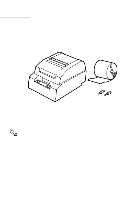
The illustration below shows the items included for the standard specification printer.
Paper roll (1 pc)
Printer |
Hexagonal lock screws (2 pcs) |
|
(only for the serial interface) |
If any item is missing or damaged, please contact your dealer for assistance.
Note:
See the Note on page 1-4 for information about the screws.
Installation 1-1
Removing the Transportation Spacer
The printer is protected during shipping by a spacer that must be removed before you turn on the printer.
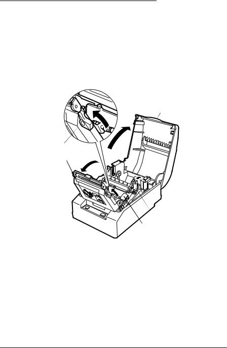
1.First, open the printer cover; next, push the auto cutter holder back and open the auto cutter; then open the head open lever, as shown by the arrows below.
Printer cover
Head open lever
Auto cutter
 Auto cutter holder
 Transportation spacer
1-2 Installation
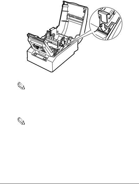
2.Next, remove the orange transportation spacer as shown by the black arrow in the illustration below. Then place the transportation spacer in the storage space provided on the printer as shown by the white arrow.
Note:
Put the transportation spacer back in its original position if you ever ship or store your printer.
3.Close the head open lever and the auto cutter. When you close the auto cutter, press firmly until it clicks.
Note:
To prevent paper jams, make sure that the auto cutter tab is underneath the auto cutter holder as shown on the auto cutter label.
Installation 1-3

Connecting the Printer to the Computer
You need an appropriate serial interface cable to connect your computer to the printer.
TM-T85
1.Make sure that the printer and the computer are turned off. Then plug the cable into the connector on the printer, as shown.
Note:
Your printer comes with inch-type hexagonal lock screws installed. If you plan to use an interface cable that requires millimeter-type lock screws, replace the inch-type screws with the enclosed millimeter-type screws by using a hex screwdriver (5 mm). To distinguish the two types of screws, see the illustration below.

 Notch (one or more lines)
Inch-type |
Millimeter-type |
2.Connect the other end of the cable to the connector on your computer.
1-4 Installation
TM-T85P
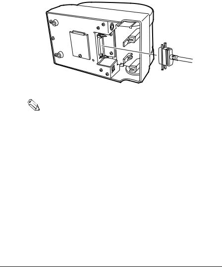
You need an appropriate parallel interface cable to connect your computer to the printer.
1.Make sure that the printer and the computer are turned off. Then plug the cable into the connector on the printer, as shown.
Note:
Squeeze the wire clips on the printer together until they lock in place on both sides of the connector.
2.Connect the other end of the cable to the connector on your computer.
Installation 1-5

Connecting the Printer to the Drawer
Plug the drawer cable into the drawer kick-out connector on the bottom of the printer next to the computer interface connector.
TM-T85
TM-T85P
 CAUTION:
Do not connect a telephone line to the drawer kick out connector.
1-6 Installation

Den Drucker an die Lade anschließen
Das Kabel der Lade an die Schnappsteckerbuchse (neben der Schnittstellenbuchse) an der Uinterseite des Druckers anschließen.
TM-T85
TM-T85P
 ACHTUNG:
Kein Telefonkabel an die Schnappsteckerbuchse anschließen.
Installation 1-7

Grounding the Printer
You need a ground wire to ground your printer. Recommended wire is described below.
Thickness of wire: |
AWG 18 or equivalent |
Diameter of terminal to be attached: |
3.2 |
1.Make sure that the printer is turned off.
2.Connect the ground wire to the printer using the FG screw on the bottom of the printer, as shown.
TM-T85
TM-T85P
1-8 Installation

Connecting the Power Supply
This printer requires an external power supply. The Epson Power Supply PS-150 is recommended.
 CAUTION:
Using an incorrect power supply can cause serious damage to the printer.
1.Make sure that the power supply is turned off.
2.Plug the power supply’s cable into the printer’s connector as shown below. Note that the flat side of the connector faces down.
TM-T85
TM-T85P
3. Plug the power supply’s cord into an outlet.
Installation 1-9
Arranging the Interface Cable
After you have plugged in all the cables, put the interface cable between the feet on the bottom of the printer and the cable-holding posts, as shown in the illustration below. This helps keep the cable securely fastened.
Installing the Paper Roll
The procedure describes how to install a paper roll for the first time. If you are replacing a used-up paper roll, see page 2-2.
Note:
Be sure to use roll paper that meets the specifications.
1. Open the printer cover. Do not open the auto cutter.
Note:
To prevent paper jams, make sure that the auto cutter tab is underneath the auto cutter holder as shown on the auto cutter label.
1-10 Installation
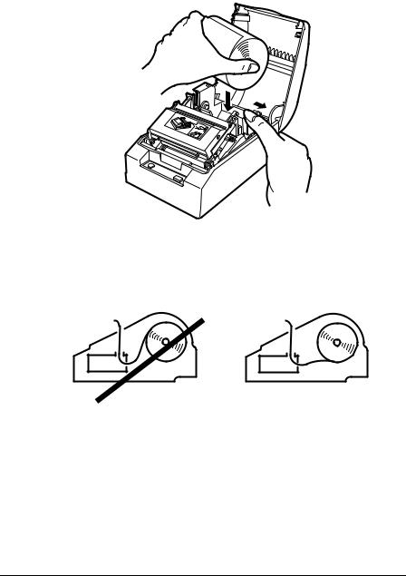
2. Spread the roll paper holder and insert the paper roll as shown.
3.Be sure to note the correct direction that the paper comes off the roll.
4.Hold both edges of the paper and insert it straight into the paper slot. Push the paper into the paper slot until the printer feeds the paper automatically and it comes out of the paper exit.
Installation 1-11

Note:
The paper is cut by the auto cutter.
Note:
If paper is inserted incorrectly, it may wrinkle. If it wrinkles, feed the paper with the PAPER FEED button until it is smooth.
1-12 Installation

5. Remove the cut paper and close the printer cover.
Running the Self Test
Any time that you want to check the performance of your printer you can run the self test described below. This shows whether your printer is working correctly. It is independent of any other equipment or software.
1.To perform the self test, close the printer cover if it is open and hold down the PAPER FEED button while you turn on the printer with the POWER button.
2.The printer prints the current printer settings and then the following message:
Self-test printing.
Please press the PAPER FEED button.
Installation 1-13
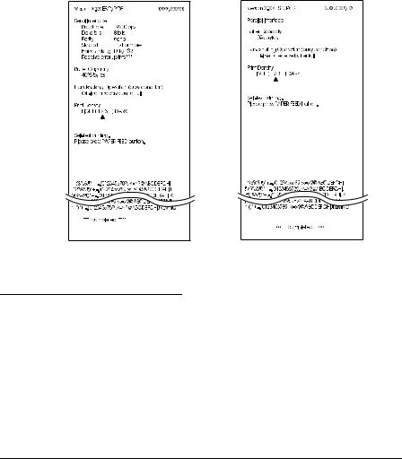
3.Press the PAPER FEED button to start the second part of the test, in which the printer prints a pattern using the built-in character set. It also performs several partial cuts and prints the following:
***completed ***
4.Then it performs a full cut and enters the normal mode.
Part of a sample self test is shown below:
TM-T85 |
TM-T85P |
Setting the DIP Switches
You can change the print density or any of your interface settings by changing the DIP switch settings.
1. Make sure that the printer is off.
1-14 Installation

2.Turn the printer over and remove the DIP switch access cover, as shown below.
TM-T85
DSW 1 |
DSW 2 |
TM-T85P
DSW 1
3.Notice that ON is marked on the switches. Use tweezers or another narrow tool to move the switches.
Installation 1-15

4.Use the following tables to set the DIP switches. Numbers starting with 1 are in the first set, and numbers starting with 2 are in the second (only for TM-T85).
TM-T85 DIP-Switch Functions
DIP Switch Set 1
Switch |
Function |
ON |
OFF |
|
|
|
|
1-1 |
Data reception error |
Ignored |
Prints”?” |
|
|
|
|
1-2 |
Receive buffer capacity |
45 bytes |
4K bytes |
|
|
|
|
1-3 |
Handshaking |
XON/XOFF |
DTR/DSR |
|
|
|
|
1-4 |
Word length |
7 bits |
8 bits |
|
|
|
|
1-5 |
Parity check |
Yes |
No |
|
|
|
|
1-6 |
Parity selection |
Even |
Odd |
|
|
|
|
1-7 |
See Transmission Speeds table below |
|
|
|
|
||
1-8 |
|
||
|
|
|
|
|
|
|
|
Transmission Speeds
Speed in Bits per Second |
SW 1-7 |
SW 1-8 |
|
|
|
2400 |
ON |
ON |
|
|
|
4800 |
OFF |
ON |
|
|
|
9600 |
ON |
OFF |
|
|
|
19200 |
OFF |
OFF |
|
|
|
DIP Switch Set 2
Switch |
Function |
ON |
OFF |
|
|
|
|
|
|
2-1 |
Handshaking (BUSY |
Receive buffer full |
Off line or receive |
|
condition) |
buffer full |
|||
|
|
|||
|
|
|
|
|
2-2 |
Selects print density |
See Print Density Table below |
||
|
||||
2-3 |
||||
|
|
|
||
|
|
|
|
|
1-16 Installation

DIP Switch Set 2
Switch |
Function |
ON |
OFF |
|
|
|
|
|
|
2-4 |
Reserved. Setting |
Normally OFF |
|
|
|
|
|
||
|
|
|
||
2-5 |
must not be |
Normally OFF |
|
|
|
changed |
|
|
|
2-6 |
Normally OFF |
|
||
|
|
|||
|
|
|
|
|
2-7 |
I/F pin 6 reset signal |
Enabled |
Disabled |
|
|
|
|
|
|
2-8 |
I/F pin 25 reset |
Enabled |
Disabled |
|
signal |
||||
|
|
|
||
|
|
|
|
Print Density
Print Density |
2-2 |
2-3 |
|
|
|
1 (Light) |
ON |
ON |
|
|
|
2 |
OFF |
OFF |
|
|
|
3 |
ON |
OFF |
|
|
|
4 (Dark) |
OFF |
ON |
|
|
|
TM-T85P DIP-Switch Functions
DIP Switch Set 1
Switch |
Function |
ON |
OFF |
|
|
|
|
|
|
1-1 |
Auto-line feed |
Enabled |
Disabled |
|
|
|
|
|
|
1-2 |
Receive buffer |
45 byte |
4K bytes |
|
capacity |
||||
|
|
|
||
|
|
|
|
|
|
Handshaking (BUSY |
Receive buffer full |
Off line, receive |
|
1-3 |
buffer full, or |
|||
condition) |
or reading data |
|||
|
reading data |
|||
|
|
|
||
|
|
|
|
|
1-4 |
Select print density |
See Print Density Table below |
||
|
||||
1-5 |
||||
|
|
|
||
|
|
|
|
|
1-6 |
Reserved. Setting |
Normally OFF |
|
|
|
must not be |
|
|
|
1-7 |
Normally OFF |
|
||
changed |
|
|||
|
|
|
|
|
1-8 |
Undefined |
|
|
|
|
|
|
|
|
Installation 1-17

Print Density
Switch |
Function |
|
Switch |
|
|
|
|
||
|
4 |
5 |
||
|
|
|
||
|
|
|
|
|
1 |
Light |
ON |
ON |
|
|
|
|
|
|
2 |
|
|
OFF |
OFF |
|
|
|
|
|
3 |
|
|
ON |
OFF |
|
|
|
|
|
4 |
Dark |
OFF |
ON |
|
|
|
|
|
|
Note:
If you change any DIP switch settings while the printer is turned on, the new settings will not take effect until you turn the printer off and back on or reset it (except for the DIP switches 2-7 and 2-8 of the TM-T85).
5. Replace the DIP switch cover and secure it with the screw.
1-18 Installation
Adjusting the Paper Near End Detector
The paper near end detector detects when the paper is almost gone by measuring the diameter of the paper roll. Software programs can use the ESC c 4 command to stop printing when the paper is almost gone.
If you want to change the amount of paper remaining when the printer stops printing, follow the steps below to adjust the paper near end detector.
Note:
The printer also has a paper end-detector that stops the printer at the very end of a roll. This detector cannot be turned off by software.
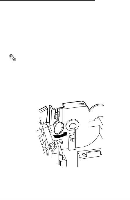
1.Open the printer cover and remove the paper roll.
2.Locate the adjusting screw and the positioning plate shown in the illustration below.
Positioning plate
Adjusting screw 

3. Loosen the adjusting screw with a coin or a screwdriver.
Installation 1-19
 Loading...