


 Loading...
Confidential
Service manual
TM-U220 Series
(Type A)
Issued date |
, |
, |
Issued by
English
EPSON
404619501 Rev. B

Confidential
TM-U220 Type A Service Manual
CONFIDENTIALITY AGREEMENT
BY USING THIS DOCUMENT, YOU AGREE TO ABIDE BY THE TERMS OF THIS AGREEMENT. PLEASE RETURN THIS DOCUMENT IMMEDIATELY IF YOU DO NOT AGREE TO THESE TERMS.
This document contains confidential, proprietary information of Seiko Epson Corporation or its affiliates. You must keep such information confidential. If the user is a business entity or organization, you must limit disclosure to those of your employees, agents, and contractors who have a need to know and who are also bound by obligations of confidentiality.
On the earlier of (a) termination of your relationship with Seiko Epson, or (b) Seiko Epson’s request, you must stop using the confidential information. You must then return or destroy the information, as directed by Seiko Epson.
If a court, arbitrator, government agency, or the like orders you to disclose any confidential information, you must immediately notify Seiko Epson. You agree to give Seiko Epson reasonable cooperation and assistance in the negotiation.
You may use confidential information only for the purpose of operating or servicing the products to which the document relates, unless you obtain the prior written consent of Seiko Epson for some other use.
Seiko Epson warrants that it has the right to disclose the confidential information. SEIKO EPSON MAKES NO OTHER WARRANTIES CONCERNING THE CONFIDENTIAL INFORMATION OR ANY OTHER INFORMATION IN THE DOCUMENT, INCLUDING (WITHOUT LIMITATION) ANY WARRANTY OF TITLE OR NON-INFRINGEMENT. Seiko Epson has no liability for loss or damage arising from or relating to your use of or reliance on the information in the document.
You may not reproduce, store, or transmit the confidential information in any form or by any means (electronic, mechanical, photocopying, recording, or otherwise) without the prior written permission of Seiko Epson.
Your obligations under this Agreement are in addition to any other legal obligations. Seiko Epson does not waive any right under this Agreement by failing to exercise it. The laws of Japan apply to this Agreement.
Cautions
No part of this document may be reproduced, stored in a retrieval system, or transmitted in any form or by any means, electronic, mechanical, photocopying, recording, or otherwise, without the prior written permission of Seiko Epson Corporation.
The contents of this document are subject to change without notice. Please contact us for the latest information.
While every precaution has been taken in the preparation of this document, Seiko Epson Corporation assumes no responsibility for errors or omissions.
Neither is any liability assumed for damages resulting from the use of the information contained herein.
Neither Seiko Epson Corporation nor its affiliates shall be liable to the purchaser of this product or third parties for damages, losses, costs, or expenses incurred by the purchaser or third parties as a result of: accident, misuse, or abuse of this product or unauthorized modifications, repairs, or alterations to this product, or (excluding the U.S.) failure to strictly comply with Seiko Epson Corporation’s operating and maintenance instructions.
Seiko Epson Corporation shall not be liable against any damages or problems arising from the use of any options or any consumable products other than those designated as Original EPSON Products or EPSON Approved Products by Seiko Epson Corporation.
EPSON® and ESC/POS® are registered trademarks of Seiko Epson Corporation
Rev. B |
i |

Confidential
Contents
Revision Table . . . . . . . . . . . . . . . . . . . . . . . . . . . . . . . . . . . . . . . . . . . . . . . . . . . . . . . . . . . . . . . . . . . . . . . .iv For Safe Repair and Maintenance Work . . . . . . . . . . . . . . . . . . . . . . . . . . . . . . . . . . . . . . . . . . . . . . . . . .v Key to Symbols . . . . . . . . . . . . . . . . . . . . . . . . . . . . . . . . . . . . . . . . . . . . . . . . . . . . . . . . . . . . . . . . . . . .v Safety Precautions on Maintenance/Repair/Inspection . . . . . . . . . . . . . . . . . . . . . . . . . . . . . . . . .vi Modular Connectors . . . . . . . . . . . . . . . . . . . . . . . . . . . . . . . . . . . . . . . . . . . . . . . . . . . . . . . . . . . . . . . . . . .vi About this Manual . . . . . . . . . . . . . . . . . . . . . . . . . . . . . . . . . . . . . . . . . . . . . . . . . . . . . . . . . . . . . . . . . . . . .vii Aim of the Manual . . . . . . . . . . . . . . . . . . . . . . . . . . . . . . . . . . . . . . . . . . . . . . . . . . . . . . . . . . . . . . . . .vii Manual Content . . . . . . . . . . . . . . . . . . . . . . . . . . . . . . . . . . . . . . . . . . . . . . . . . . . . . . . . . . . . . . . . . . .vii
Chapter 1 Product Overview |
|
Notes on Connecting the Power Supply Unit . . . . . . . . . . . . . . . . . . . . . . . . . . . . . . . . . . . . . . . . . . . |
1-1 |
Configurations . . . . . . . . . . . . . . . . . . . . . . . . . . . . . . . . . . . . . . . . . . . . . . . . . . . . . . . . . . . . . . . . . . . . . . . . |
1-2 |
Part Names . . . . . . . . . . . . . . . . . . . . . . . . . . . . . . . . . . . . . . . . . . . . . . . . . . . . . . . . . . . . . . . . . . . . . . . . . . . |
1-2 |
Control Panel (LEDs and Button) . . . . . . . . . . . . . . . . . . . . . . . . . . . . . . . . . . . . . . . . . . . . . . . . . . . . . . . . . |
1-3 |
LEDs . . . . . . . . . . . . . . . . . . . . . . . . . . . . . . . . . . . . . . . . . . . . . . . . . . . . . . . . . . . . . . . . . . . . . . . . . . . . . |
1-3 |
Button . . . . . . . . . . . . . . . . . . . . . . . . . . . . . . . . . . . . . . . . . . . . . . . . . . . . . . . . . . . . . . . . . . . . . . . . . . . . |
1-3 |
Power Switch and Power Switch Cover . . . . . . . . . . . . . . . . . . . . . . . . . . . . . . . . . . . . . . . . . . . . . . . . . . . |
1-3 |
Power Switch Cover . . . . . . . . . . . . . . . . . . . . . . . . . . . . . . . . . . . . . . . . . . . . . . . . . . . . . . . . . . . . . . . . |
1-3 |
Inserting Roll Paper . . . . . . . . . . . . . . . . . . . . . . . . . . . . . . . . . . . . . . . . . . . . . . . . . . . . . . . . . . . . . . . . . . . . |
1-4 |
Installing or Replacing the Ribbon Cassette . . . . . . . . . . . . . . . . . . . . . . . . . . . . . . . . . . . . . . . . . . . . . . . |
1-7 |
Differences between the TM-U300, TM-U200, and TM-U220 . . . . . . . . . . . . . . . . . . . . . . . . . . . . . . . . . . |
1-8 |
Chapter 2 Repair Guide
Repair Process . . . . . . . . . . . . . . . . . . . . . . . . . . . . . . . . . . . . . . . . . . . . . . . . . . . . . . . . . . . . . . . . . . . . . . . .2-1
Outline of Repair . . . . . . . . . . . . . . . . . . . . . . . . . . . . . . . . . . . . . . . . . . . . . . . . . . . . . . . . . . . . . . . . . .2-1
Repair Flow . . . . . . . . . . . . . . . . . . . . . . . . . . . . . . . . . . . . . . . . . . . . . . . . . . . . . . . . . . . . . . . . . . . . . . .2-1
Confirming the User’s Environment . . . . . . . . . . . . . . . . . . . . . . . . . . . . . . . . . . . . . . . . . . . . . . . . . . .2-1
Confirming the Printer Status . . . . . . . . . . . . . . . . . . . . . . . . . . . . . . . . . . . . . . . . . . . . . . . . . . . . . . . . .2-1
Self-test . . . . . . . . . . . . . . . . . . . . . . . . . . . . . . . . . . . . . . . . . . . . . . . . . . . . . . . . . . . . . . . . . . . . . . . . . .2-2
Service Utility . . . . . . . . . . . . . . . . . . . . . . . . . . . . . . . . . . . . . . . . . . . . . . . . . . . . . . . . . . . . . . . . . . . . . .2-5
Chapter 3 Troubleshooting |
|
Preparations for Troubleshooting . . . . . . . . . . . . . . . . . . . . . . . . . . . . . . . . . . . . . . . . . . . . . . . . . . . . . . . . . |
3-1 |
Before Servicing . . . . . . . . . . . . . . . . . . . . . . . . . . . . . . . . . . . . . . . . . . . . . . . . . . . . . . . . . . . . . . . . . . . . . . . |
3-2 |
Diagnosing Failures . . . . . . . . . . . . . . . . . . . . . . . . . . . . . . . . . . . . . . . . . . . . . . . . . . . . . . . . . . . . . . . . . . . . |
3-2 |
Symptoms and Solutions . . . . . . . . . . . . . . . . . . . . . . . . . . . . . . . . . . . . . . . . . . . . . . . . . . . . . . . . . . . . . . . . |
3-3 |
Symptoms when Power is On . . . . . . . . . . . . . . . . . . . . . . . . . . . . . . . . . . . . . . . . . . . . . . . . . . . . . . . . |
3-3 |
Symptoms when the All Function Test is Executed . . . . . . . . . . . . . . . . . . . . . . . . . . . . . . . . . . . . . . . |
3-15 |
Symptoms for other operations . . . . . . . . . . . . . . . . . . . . . . . . . . . . . . . . . . . . . . . . . . . . . . . . . . . . . . |
3-20 |
Test Points on the Main Circuit Board Unit . . . . . . . . . . . . . . . . . . . . . . . . . . . . . . . . . . . . . . . . . . . . . . . . . |
3-21 |
Resistance Values of Printer Mechanism Components . . . . . . . . . . . . . . . . . . . . . . . . . . . . . . . . . . . . . . |
3-22 |
Chapter 4 Disassembly and Assembly
Lubricants . . . . . . . . . . . . . . . . . . . . . . . . . . . . . . . . . . . . . . . . . . . . . . . . . . . . . . . . . . . . . . . . . . . . . . . . . . . .4-1 Standard Lubrication . . . . . . . . . . . . . . . . . . . . . . . . . . . . . . . . . . . . . . . . . . . . . . . . . . . . . . . . . . . . . . .4-1 Lubricants . . . . . . . . . . . . . . . . . . . . . . . . . . . . . . . . . . . . . . . . . . . . . . . . . . . . . . . . . . . . . . . . . . . . . . . .4-1 Lubrication Points . . . . . . . . . . . . . . . . . . . . . . . . . . . . . . . . . . . . . . . . . . . . . . . . . . . . . . . . . . . . . . . . . .4-1 Tool List . . . . . . . . . . . . . . . . . . . . . . . . . . . . . . . . . . . . . . . . . . . . . . . . . . . . . . . . . . . . . . . . . . . . . . . . . . . . . .4-1 Notes for Assembly and Disassembly . . . . . . . . . . . . . . . . . . . . . . . . . . . . . . . . . . . . . . . . . . . . . . . . . . . . .4-2 Shortest Route for Disassembly of Major Parts . . . . . . . . . . . . . . . . . . . . . . . . . . . . . . . . . . . . . . . . . . . . . .4-3 Disassembling the TM-U220 . . . . . . . . . . . . . . . . . . . . . . . . . . . . . . . . . . . . . . . . . . . . . . . . . . . . . . . . . . . . .4-4 Exploded Diagram . . . . . . . . . . . . . . . . . . . . . . . . . . . . . . . . . . . . . . . . . . . . . . . . . . . . . . . . . . . . . . . . .4-4 Disassembly Procedures . . . . . . . . . . . . . . . . . . . . . . . . . . . . . . . . . . . . . . . . . . . . . . . . . . . . . . . . . . . .4-5 Disassembling the Mechanism Assembly . . . . . . . . . . . . . . . . . . . . . . . . . . . . . . . . . . . . . . . . . . . . . . . . . .4-6 Exploded Diagram . . . . . . . . . . . . . . . . . . . . . . . . . . . . . . . . . . . . . . . . . . . . . . . . . . . . . . . . . . . . . . . . .4-6
ii |
Rev. B |

Confidential
TM-U220 Type A Service Manual
DIsassembly Procedures . . . . . . . . . . . . . . . . . . . . . . . . . . . . . . . . . . . . . . . . . . . . . . . . . . . . . . . . . . . |
4-7 |
Disassembling the Carriage Unit . . . . . . . . . . . . . . . . . . . . . . . . . . . . . . . . . . . . . . . . . . . . . . . . . . . . . . . . |
4-8 |
Exploded Diagram . . . . . . . . . . . . . . . . . . . . . . . . . . . . . . . . . . . . . . . . . . . . . . . . . . . . . . . . . . . . . . . . |
4-8 |
DIsassembly Procedures . . . . . . . . . . . . . . . . . . . . . . . . . . . . . . . . . . . . . . . . . . . . . . . . . . . . . . . . . . . |
4-9 |
Disassembling the Rotation Frame Unit . . . . . . . . . . . . . . . . . . . . . . . . . . . . . . . . . . . . . . . . . . . . . . . . . . . |
4-10 |
Exploded Diagram . . . . . . . . . . . . . . . . . . . . . . . . . . . . . . . . . . . . . . . . . . . . . . . . . . . . . . . . . . . . . . . . |
4-10 |
DIsassembly Procedures . . . . . . . . . . . . . . . . . . . . . . . . . . . . . . . . . . . . . . . . . . . . . . . . . . . . . . . . . . . |
4-11 |
Disassembling the Roll Paper Guide / Roll Paper Holder . . . . . . . . . . . . . . . . . . . . . . . . . . . . . . . . . . . . |
4-12 |
Exploded Diagram . . . . . . . . . . . . . . . . . . . . . . . . . . . . . . . . . . . . . . . . . . . . . . . . . . . . . . . . . . . . . . . . |
4-12 |
DIsassembly Procedures . . . . . . . . . . . . . . . . . . . . . . . . . . . . . . . . . . . . . . . . . . . . . . . . . . . . . . . . . . . |
4-13 |
Disassembling the Autocutter Unit / Fixed Blade Holder Assembly . . . . . . . . . . . . . . . . . . . . . . . . . . . . |
4-14 |
Exploded Diagram . . . . . . . . . . . . . . . . . . . . . . . . . . . . . . . . . . . . . . . . . . . . . . . . . . . . . . . . . . . . . . . . |
4-14 |
DIsassembly Procedures . . . . . . . . . . . . . . . . . . . . . . . . . . . . . . . . . . . . . . . . . . . . . . . . . . . . . . . . . . . |
4-15 |
Disassembly and Assembly Reference . . . . . . . . . . . . . . . . . . . . . . . . . . . . . . . . . . . . . . . . . . . . . . . |
4-16 |
Lubrication Reference . . . . . . . . . . . . . . . . . . . . . . . . . . . . . . . . . . . . . . . . . . . . . . . . . . . . . . . . . . . . . |
4-28 |
Chapter 5 Adjustment and Setting |
|
Setting the Installation Position for the Roll Paper Near-End Detector . . . . . . . . . . . . . . . . . . . . . . . . . |
5-1 |
Adjusting the Detection Point for the Roll Paper Near-End Detector . . . . . . . . . . . . . . . . . . . . . . . . . . |
5-2 |
Setting the Paper Roll Width . . . . . . . . . . . . . . . . . . . . . . . . . . . . . . . . . . . . . . . . . . . . . . . . . . . . . . . . . . . . |
5-3 |
Setting the Autocutter . . . . . . . . . . . . . . . . . . . . . . . . . . . . . . . . . . . . . . . . . . . . . . . . . . . . . . . . . . . . . . . . . |
5-4 |
Platen Gap Adjustment . . . . . . . . . . . . . . . . . . . . . . . . . . . . . . . . . . . . . . . . . . . . . . . . . . . . . . . . . . . . . . . |
5-5 |
Carriage Belt Tension Adjustment . . . . . . . . . . . . . . . . . . . . . . . . . . . . . . . . . . . . . . . . . . . . . . . . . . . . . . . |
5-6 |
Adjust Various Settings . . . . . . . . . . . . . . . . . . . . . . . . . . . . . . . . . . . . . . . . . . . . . . . . . . . . . . . . . . . . . . . . . |
5-7 |
How to Confirm the Current Settings . . . . . . . . . . . . . . . . . . . . . . . . . . . . . . . . . . . . . . . . . . . . . . . . . |
5-7 |
Adjusting the DIP Switches . . . . . . . . . . . . . . . . . . . . . . . . . . . . . . . . . . . . . . . . . . . . . . . . . . . . . . . . . . |
5-7 |
Memory Switches . . . . . . . . . . . . . . . . . . . . . . . . . . . . . . . . . . . . . . . . . . . . . . . . . . . . . . . . . . . . . . . . . |
5-10 |
Memory Switch Setup Mode . . . . . . . . . . . . . . . . . . . . . . . . . . . . . . . . . . . . . . . . . . . . . . . . . . . . . . . . |
5-12 |
Chapter 6 Preparation for Shipment |
|
Inspection and Maintenance . . . . . . . . . . . . . . . . . . . . . . . . . . . . . . . . . . . . . . . . . . . . . . . . . . . . . . . . . . |
6-1 |
Maintenance Procedures . . . . . . . . . . . . . . . . . . . . . . . . . . . . . . . . . . . . . . . . . . . . . . . . . . . . . . . . . . |
6-1 |
Cleaning . . . . . . . . . . . . . . . . . . . . . . . . . . . . . . . . . . . . . . . . . . . . . . . . . . . . . . . . . . . . . . . . . . . . . . . . . . . . |
6-1 |
How to Clean the Cases . . . . . . . . . . . . . . . . . . . . . . . . . . . . . . . . . . . . . . . . . . . . . . . . . . . . . . . . . . . |
6-1 |
Removing Dirt, Paper Chips, and Dust from Inside the Printer . . . . . . . . . . . . . . . . . . . . . . . . . . . . |
6-2 |
Appendix Parts List |
|
Reference Number List . . . . . . . . . . . . . . . . . . . . . . . . . . . . . . . . . . . . . . . . . . . . . . . . . . . . . . . . . . . . . . . . |
A-1 |
Rev. B |
iii |

Confidential
Revision Table
Revision |
Pages |
Description |
|
|
|
Rev. A |
All pages |
Newly authorized. |
|
|
|
Rev. B |
1-2 |
Part names added. |
|
|
|
|
1-3 |
Control panel (LEDs and buttons) added. |
|
|
|
|
1-4 |
Inserting roll paper added. |
|
|
|
|
1-8 |
Installing and replacing the ribbon cassette added. |
|
|
|
|
4-3, 4-4 |
Illustration was changed. |
|
|
|
|
4-5, 4-16, 4-17 |
An explanation of the roll paper cover assembly was added. |
|
|
|
|
4-6, 4-7 |
Cutter rotation plate (1129) added. |
|
|
|
|
4-7 |
Step 6 added to disassembly. |
|
|
|
|
4-10, 4-11, 4-20 |
Paper feed roller plate B deleted. |
|
|
|
|
4-11 |
An explanation of the platen assembly 1 was added. |
|
|
|
|
4-30 |
An explanation of the lubrication reference was added. |
|
|
|
|
Chapter 6 |
Inserting roll paper and installing or replacing the ribbon cassette was |
|
|
moved to Chapter 1. |
|
|
|
iv |
Rev. B |

Confidential
For Safe Repair and Maintenance Work
TM-U220 Type A Service Manual
Key to Symbols
The symbols in this manual are identified by their level of importance, as defined below. Read the following carefully before handling the product.
 WARNING:
You must follow warnings carefully to avoid serious bodily injury.
 CAUTION:
Observe cautions to avoid minor injury to yourself, damage to your equipment, or loss of data.
Note:
Notes have important information and useful tips on the operation of your equipment.
Rev. B |
v |

Confidential
Safety Precautions on Maintenance/Repair/Inspection
 WARNING:
Be sure to use the EPSON-supplied fuse on the circuit board. Use of another fuse may result in fire.
Remove the power cord and all other cables from this product before disassembly or reassembly to prevent electrical shock.
To prevent the possibility of electrical shock, do not perform maintenance, repair, or inspection during a thunderstorm.
Shut down your equipment immediately if it produces smoke, a strange odor, or unusual noise. Continued use may lead to fire or electric shock. Immediately unplug the equipment.
Only disassemble this product as described in this manual. Do not make modifications to the unit. Tampering with this product may result in injury, fire, or electric shock.
Be sure to use the specified power source. Connection to an improper power source may cause fire or shock.
Never insert or disconnect the power plug with wet hands. Doing so may result in severe shock.
 CAUTION:
Parts on the circuit board may become hot during operation. Therefore, wait approximately 10 minutes after turning the power off before touching them.
To avoid injury, take care not to insert fingers or any part of the hand in the paper roll opening where the manual cutter is installed.
Do not open the paper roll cover without taking the necessary precautions, as this can result in injury from the autocutter fixed blade.
Modular Connectors
Use the modular connectors specifically designed for the cash drawer and customer display for this product. Do not connect these connectors to an ordinary telephone line.
vi |
Rev. B |

Confidential
About this Manual
TM-U220 Type A Service Manual
Aim of the Manual
This manual was created to provide the information on printer maintenance and repair required by technicians who handle this work.
Manual Content
The manual is made up of the following sections
Chapter 1 |
Product Overview |
Provides an overview of the product. |
Chapter 2 |
Repair Guide |
Describes the instructions to complete repair of |
|
|
the product. |
Chapter 3 |
Troubleshooting |
Provides information on troubleshooting. |
Chapter 4 |
Disassembly and |
Describes disassembly and assembly procedures. |
|
Assembly |
Also, shows exploded diagrams and lubrication |
|
|
point diagrams for this product. |
Chapter 5 |
Adjustments and Settings |
Describes adjusting and settings procedures. |
Chapter 6 |
Preparation for shipment |
Describes preparation for transport. Also |
|
|
provides information on maintenance, |
|
|
inspection, and cleaning. |
Appendix |
Parts List |
Provides a parts list. Also describes screw types. |
Rev. B |
vii |
Confidential
Chapter 1
TM-U220 Type A Service Manual
Product Overview
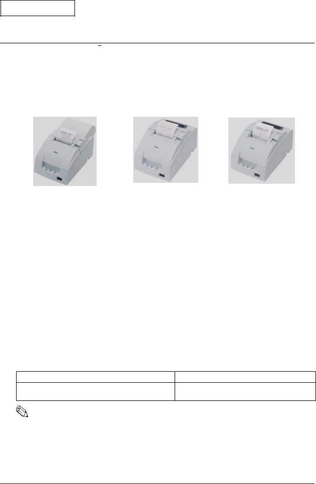
The TM-U220 is a serial impact dot-matrix printer for POS systems that can print on roll paper of various widths. This manual describes the TM-U220 Type A, which has a take-up shaft for journal paper. The following model types are available for the TM-U220.
Type A |
Type B |
Type D |
TM-U220 external views
TM-U220 Model Comparison
|
Type A |
Type B |
Type D |
|
|
|
|
|
|
Two-color printing |
Yes |
Yes |
Yes |
|
|
|
|
|
|
Autocutter |
Yes |
Yes |
No |
|
|
|
|
|
|
Take-up device |
Yes |
No |
No |
|
|
|
|
|
|
Paper width |
76 / 69.5 / 57.5 mm |
76 / 69.5 / 57.5 mm |
76 / 69.5 / 57.5 mm |
|
{3" / 2.74" / 2.26"} |
{3" / 2.74" / 2.26"} |
{3" / 2.74" / 2.26"} |
||
|
||||
|
|
|
|
|
Interface (supplied with printer)* |
Serial or parallel |
Serial or parallel |
Serial or parallel |
|
|
|
|
|
|
Characters supported |
Alphanumeric (ANK) or |
Alphanumeric (ANK) or |
Alphanumeric (ANK) or |
|
multilingual** |
multilingual** |
multilingual** |
||
|
||||
|
|
|
|
Note: * Other compatible interfaces, such as USB and Ethernet, are available from the dealer.
**Multilingual support means that the printer can print any one of the following: Japanese Kanji, Simplified Chinese, Traditional Chinese, Thai characters, or Korean characters.
Notes on Connecting the Power Supply Unit
Be sure to use the correct power supply unit, as listed in the table below.
TM-U220 alphanumeric model |
TM-U220 multilingual model |
1. AC adapter C (packed with the alphanumeric model)
PS-180 (packed with the multilingual model)
2. PS-180 (option)
Note:
The AC adapter C, which is packed with the alphanumeric model, cannot be used with the multilingual model. Be sure to use the PS-180 with the multilingual model. If the AC adapter C power supply is connected to the multilingual model by mistake, the printer may not operate correctly. For example, printing may stop before all lines are printed, or the printer might print the same line repeatedly.
Rev. B |
Product Overview 1-1 |

Confidential
Configurations
This TM-U220 is configured by combining features from the list below.
Table 1-1 Configurations
Features |
Selection |
Description |
|
|
|
|
|
|
UB-S01 (RS-232) |
|
|
Interface types |
UB-P02II (IEEE 1284 (bidirectional parallel)) |
Use an EPSON-approved interface board |
|
EPSON UB universal interface board |
|||
|
|
||
|
options |
|
|
|
|
|
|
|
|
Be sure to change the paper guide |
|
|
|
spacer if paper of a different width is used. |
|
Paper width selections |
76, 69.5, or 57.5 mm {3", 2.74", or 2.26"} |
Then, set the customized value in printer |
|
memory for the correct paper width. For |
|||
|
|
||
|
|
details about how to set the paper width, |
|
|
|
see Chapter 6, “Installation.” |
|
|
|
|
|
|
Exclusive external power supply for the |
|
|
|
alphanumeric model: |
|
|
|
AC Adapter C (North America only) |
Do not use the AC Adapter C with the |
|
Power supply unit types |
(pre-packaged). |
||
multilingual model. |
|||
|
External power supply unit for the |
||
|
|
||
|
multilingual model: |
|
|
|
PS-180 |
|
|
|
|
|
|
|
Horizontally (default) |
|
|
Installation positions |
Vertically by use of the optional WH-10 |
|
|
|
wall-hanging bracket |
|
|
|
|
|
Note: Selections in the table above may be added to or changed in the future. dpi: dots per 25.4 mm (dots per inch)
Part Names
The figure below shows part names for the TM-U220.
Roll paper cover 
 Ribbon cassette cover
Power switch
Control panel 
1-2 Product Overview |
Rev. B |
Confidential
Control Panel (LEDs and Button)
TM-U220 Type A Service Manual
LEDs
POWER
On when power is on.
ERROR
On when printer is offline. Off when printer is online. Flashes during an error.
PAPER OUT
On when paper is out or nearly out. Flashes during self-test
Button
FEED
This button feeds roll paper or starts a self-test.
Note:
Paper cannot be fed by using this button when a paper out is detected.
Power Switch and Power Switch Cover
The power switch is on the front of the printer. Press this switch to turn on the printer.
Power Switch Cover
This cover prevents the power from being turned off accidentally during printing. If you need to turn the power on or off while the cover is attached, you can insert a small screwdriver or similar tool into one of the holes in the cover to flip the switch.
 WARNING:
If an accident occurs while the power switch cover is attached, immediately unplug the power supply cable to avoid fire.
Rev. B |
Product Overview 1-3 |
Confidential
Inserting Roll Paper
 CAUTION:
Be sure to use only roll paper that meets the specifications.
Be sure not to touch the manual cutter. Otherwise, you may cut your fingers.
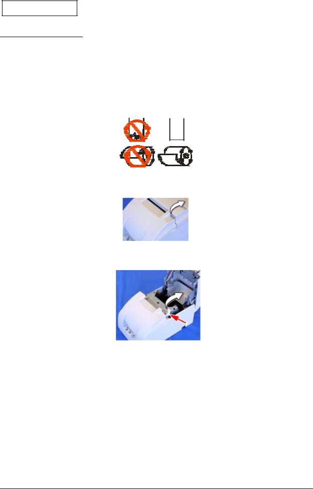
1. Using scissors, cut the leading edge of the roll paper.
2. Turn on the printer and open the roll paper cover by using the tab.
3. Open the unit by using the unit open lever, as shown below.
Unit open lever
1-4 Product Overview |
Rev. B |
Confidential
TM-U220 Type A Service Manual
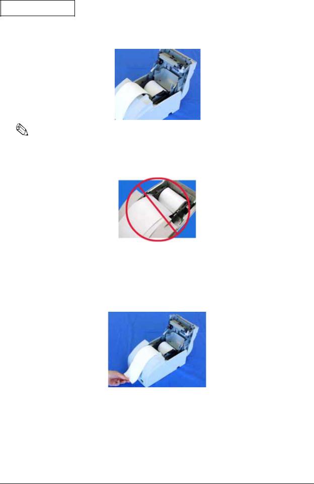
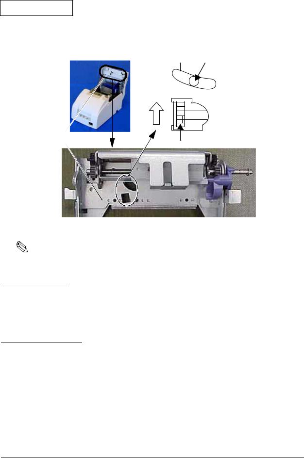
4. Insert the roll paper.
Note:
Note the direction that the paper comes off the roll, as shown above.
When using two-ply paper, be sure that the top and bottom sheets are aligned at the paper exit. Do not allow paper to be loaded as shown below.
5.If you are not using the take-up flange, pull out a small amount of roll paper and close the roll paper cover. Then, tear off the paper with the manual cutter. You can skip steps 6 through 11.
6.When using 2-ply roll paper, pull out the roll paper to the bottom front of the printer, as shown below.
Rev. B |
Product Overview 1-5 |

Confidential
7. Close the unit, as shown below.
8.Insert the end of the bottom layer of paper (journal paper) into the paper take-up flange, as shown below.
Take-up flange
9.Insert the paper take-up flange into the printer. Be sure that the paper is aligned with the flange, as shown.
10.Feed the paper with the FEED button so that the paper is taken up by the flange.
11.Close the roll paper cover and tear off the roll paper with the manual cutter, as shown below.
Note:
Do not open the roll paper cover during printing or paper feeding.
When using the printer, be sure to cut the roll paper with the manual cutter after paper feeding is complete.
1-6 Product Overview |
Rev. B |
Confidential
Installing or Replacing the Ribbon Cassette
TM-U220 Type A Service Manual
 CAUTION:
EPSON recommends the use of only genuine EPSON ribbon cassettes. Ribbon cassettes not manufactured by EPSON may cause damage to your printer that is not covered by EPSON’s warranties.
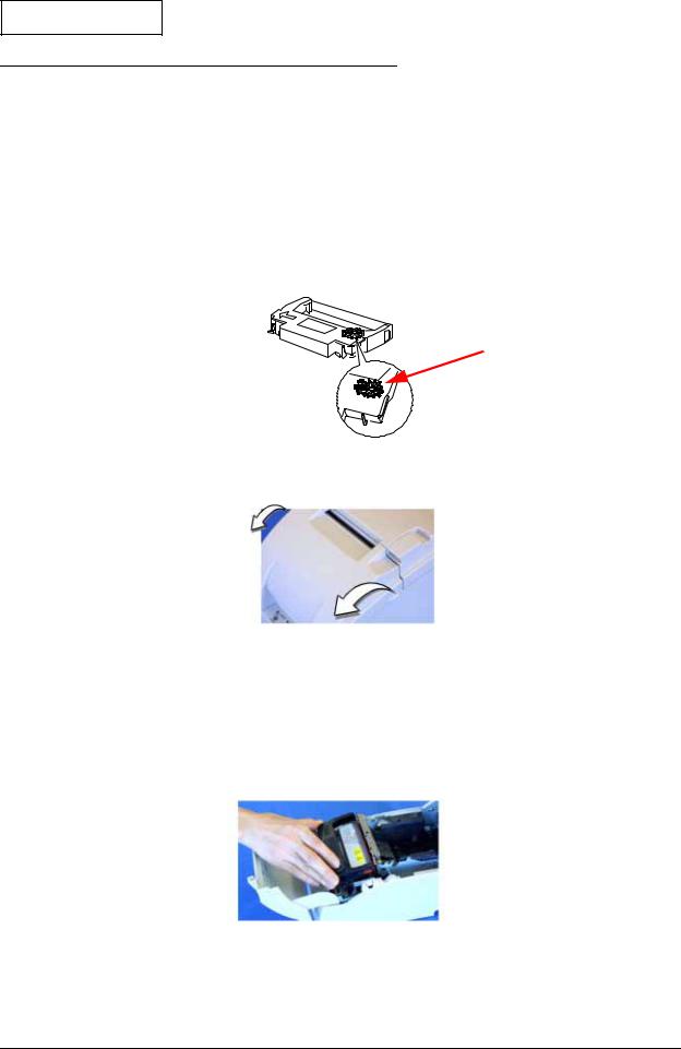
To install the ribbon cassette for the first time or to replace a used ribbon, follow the steps below. 1. Unpack the ribbon cassette and turn the knob in the direction shown to take up any slack.
Knob
2. Open the printer’s ribbon cassette cover using the tabs on each side of the cover.
3.Remove the old ribbon, if there is one.
4.Insert cassette as shown below. Put ribbon between print head and platen. Push cassette down until it clicks.
 Note:
Note:
Make sure the ribbon is installed between the print head and the platen without wrinkles or creases.
5.Again, turn the cassette knob 2 or 3 times to take up slack.
6.Close the printer’s ribbon cassette cover.
Rev. B |
Product Overview 1-7 |

Confidential
Differences between the TM-U300, TM-U200, and TM-U220
Specification |
TM-U300 (Type A, B, C, D) |
TM-U200 (Type A, B, D) |
TM-U220 (Type A, B, D) |
||||||
|
|
|
|
||||||
Print speed |
3.5 lines/second (at 40 columns, 16 cpi) |
3.5 lines/second (at 40 columns, 16 cpi) |
4.7 lines/second (at 40 columns, 16 cpi) |
||||||
|
|
|
|
|
|
|
|||
Paper feed speed |
25 lines/second |
|
25 lines/second |
|
30 lines/ second |
|
|||
|
|
|
|
||||||
Character tables |
Alphanumeric 95, international 32, |
Alphanumeric 95, international 32, |
Alphanumeric 95, international 48, |
||||||
|
extended 126 x 7 |
|
extended 128 x 8 |
|
extended 128 x 12 |
|
|||
|
|
|
|
|
|||||
Paper loading |
Paper roll holding shaft |
Semi automatic loading |
Drop in loading |
|
|||||
|
|
|
|
|
|
|
|
|
|
Paper near-end sensor |
Yes |
|
|
Option |
|
|
Configured option |
|
|
|
|
|
|
|
|
|
|
|
|
Cover open detector |
Yes |
|
|
No |
|
|
Yes |
|
|
|
|
|
|
|
|
|
|
||
Paper width |
76 mm |
|
|
76 mm |
|
|
76 mm, 69.5 mm, or 57.5 (B and D only) |
||
|
|
|
|
||||||
Number of copies |
Original + 2 copies (at 77°F) |
A and B: original + 1 copy; |
All models: original + 1 copy |
||||||
|
Original + 1 copy (at all temperatures) |
D: original + 2 copies |
|
|
|
||||
|
|
|
|
|
|||||
Autocutter |
Full cut or partial cut set by command |
Partial cut default; |
|
Partial/full cut set by command |
|||||
(Type A, B only) |
|
|
|
full cut set by command |
|
|
|
||
|
|
|
|
|
|
|
|
|
|
Auto take-up unit |
Type A, C |
|
|
Type A |
|
|
Type A |
|
|
|
|
|
|
|
|
|
|||
Print area |
76 mm paper: |
|
76 mm paper: |
|
76 mm paper: |
|
|||
|
Width: |
|
63.34 mm (200 dots x |
Width: |
|
63.34 mm (200 dots x |
Width: |
|
63.34 mm (200 dots x |
|
|
|
400 positions) |
|
|
400 positions) |
|
|
400 positions) |
|
Left margin: |
6 mm |
Left margin: |
5.9 mm |
Left margin: |
6.8 mm |
|||
|
Right margin: |
6.5 mm (approx.) |
Right margin: |
6.76 mm |
Right margin: |
5.8 mm |
|||
|
|
|
|
|
|
|
69.5 mm paper: |
|
|
|
|
|
|
|
|
|
Width: |
|
57 mm (180 dots x |
|
|
|
|
|
|
|
|
|
360 positions) |
|
|
|
|
|
|
|
Left margin: |
6.7 mm |
|
|
|
|
|
|
|
|
Right margin: |
5.8 mm |
|
|
|
|
|
|
|
|
57.5 mm paper: |
|
|
|
|
|
|
|
|
|
Width: |
|
47.5 mm (150 dots x |
|
|
|
|
|
|
|
|
|
300 positions) |
|
|
|
|
|
|
|
Left margin: |
4.2 mm |
|
|
|
|
|
|
|
|
Right margin: |
5.8 mm |
|
|
|
|
|
|
|
|
|
|
|
Space from autocut to |
36 mm |
|
|
27 mm |
|
|
27 mm |
|
|
print start: |
|
|
|
|
|
|
|
|
|
Space from manual cut to |
Type A, B: 26 mm; Type C, D: 28 mm |
20.2 mm |
|
|
Type D: 22.1 mm; Type A, B: 34.9 mm |
||||
print start: |
|
|
|
|
|
|
|
|
|
|
|
|
|
|
|
|
|||
Receive buffer |
Alphanumeric: |
1KB/40 bytes |
Alphanumeric: |
1KB/40 bytes |
Alphanumeric: |
4KB/40 bytes |
|||
|
Multilingual: |
512 bytes/40 bytes |
Multilingual: |
512 bytes/40 bytes |
Multilingual: |
4KB/40 bytes |
|||
|
|
|
|
|
|
|
|||
NV bit image memory |
Alphanumeric: |
none |
Alphanumeric: |
none |
Alphanumeric: |
128KB |
|||
|
Multilingual: |
none |
Multilingual: |
none |
Multilingual: |
128KB |
|||
|
|
|
|
|
|
|
|||
NV user memory |
Alphanumeric: |
none |
Alphanumeric: |
none |
Alphanumeric: |
8KB |
|||
|
Multilingual: |
none |
Multilingual: |
none |
Multilingual: |
8KB |
|||
|
|
|
|
||||||
Power supply |
PA-6509 or PB-6509 (North America) |
PB-6509 (North America) |
AC Adapter C — Low-cost universal |
||||||
|
|
|
|
|
|
|
power supply for impact dot matrix |
||
|
|
|
|
|
|
|
printer supplied in box. |
||
|
|
|
|
||||||
Dimensions (W x D x H) |
Type A: 170 x 288 x 183 mm |
Type A: 160 x 295 x 160 mm |
Type A: 160 x 286 x 157.5 mm |
||||||
|
|
{6.7 x 11.3 x 7.2"} |
|
{6.3 x 11.6 x 6.3"} |
|
{6.3 x 11.3 x 6.2"} |
|||
|
Type B: |
170 x 253 x 148 mm |
Type B: |
160 x 248 x 150 mm |
Type B: |
160 x 248 x 138.5 mm |
|||
|
|
{6.7 x 10 x 5.8"} |
|
{6.3 x 9.8 x 5.9"} |
|
{6.3 x 9.8 x 5.5"} |
|||
|
Type C: 158 x 295 x 145 mm |
Type D: 160 x 248 x 133 mm |
Type D: 160 x 248 x 138.5 mm |
||||||
|
|
{6.2 x 11.6 x 5.7"} |
|
{6.3 x 9.8 x 5.2"} |
|
{6.3 x 9.8 x 5.5"} |
|||
|
Type D: 158 x 235 x 125 mm |
|
|
|
|
|
|
||
|
|
{6.2 x 9.3 x 4.9"} |
|
|
|
|
|
|
|
|
|
|
|
||||||
Installation |
Horizontally with a 15° slant, maximum. |
Horizontally with a 15° slant, maximum. |
Horizontally with a 15° slant, maximum. |
||||||
|
Type B, D: Vertically on wall using WH-10 |
|
|
|
Optional IR tray also can be used. |
||||
|
bracket. |
|
|
|
|
|
Type B, D: Vertically on wall using WH-10 |
||
|
|
|
|
|
|
|
bracket. |
|
|
|
|
|
|
|
|
|
|
||
Buzzer |
None |
|
|
None |
|
|
Printer also can be used with annunciator |
||
|
|
|
|
|
|
|
interface. |
|
|
|
|
|
|
|
|
|
|
|
|
1-8 Product Overview |
Rev. B |
Confidential
Chapter 2
TM-U220 Type A Service Manual
Repair Guide
This chapter gives instructions to complete repair of the product. Follow the process in this section for repair.
Repair Process
Outline of Repair
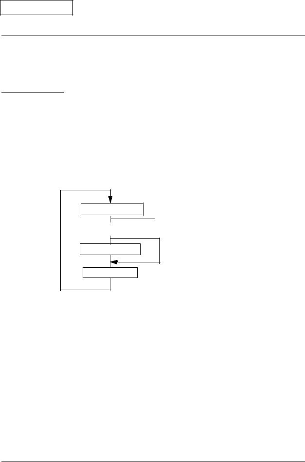
Check each item before and after repair, as shown in the following flowchart. This chapter explains the operations to confirm a “normal state” of operation of items in the flowchart. If an item is in a state other than the “normal state,” follow the instructions in the chapter to troubleshoot based on the symptom.
Repair Flow
Confirm the right status
 If no problem is found, the product is considered to be
Troubleshooting |
|
normal, and can be sent to the user’s environment. |
|
|
|
|
|
|
|
|
|
Assembly/disassembly |
Adjustment/setting
Confirming the User’s Environment
Confirm the printer’s settings by using the service utility.
Confirming the Printer Status
Confirm the status of the printer you are repairing. Confirm that the power turns on/off; run the self-test; run all function tests with the service utility; and check other items, following the table below. Perform the appropriate measures for the symptom.
Rev. B |
Repair Guide 2-1 |

Confidential
Printer Status Checks
Operation |
Normal printer operation |
When a problem occurs |
|
|
|
|
|
|
Power LED light comes on. |
POWER LED does not light. (See page 3-3.) |
|
|
ERROR LED light. (See page 3-3.) |
||
Power on. |
Mechanical initializing operation occurs. |
||
ERROR LED flashes. (See page 3-4.) |
|||
|
ERROR LED light is off. |
||
|
PAPER OUT LED lights. (See page 3-6.) |
||
|
|
||
|
|
|
|
|
POWER LED light comes on. |
Self-test cannot be performed. (See page 3-6.) |
|
|
Prints the printer status. (See page 2-3.) |
||
Run the self-test. |
Printing cannot be performed. (See page 3-7.) |
||
Prints the roll pattern after the FEED button |
|||
*Refer to page 2-2 |
The print result is not normal. (See page 3-12.) |
||
is pressed. (See page 2-3.) |
|||
for operation. |
A paper jam occurs. (See page 3-14.) |
||
Mechanical initialization occurs. |
|||
|
PAPER OUT LED lights. (See page 3-6.) |
||
|
ERROR LED light is off. |
||
|
|
||
|
|
|
|
Run the “all |
Reads printer status. |
The communication test fails. (See page 3-16.) |
|
function test” with |
Prints the RECEIPT sheet. (See page 2-9.) |
||
The print result is not normal. (See page 3-12.) |
|||
the service utility. |
Prints the STATUS sheet after confirming the |
||
Drawer kick is not performed. (See page 3-17.) |
|||
*Refer to page 2-7 |
sensor operation. (See page 2-10.) |
||
The sensor does not work. (See page 3-18.) |
|||
for operation. |
Prints the REPORT sheet. (See page 2-12.) |
||
|
|||
|
|
|
|
Perform other |
Normal opening/closing of roll paper |
|
|
cover. |
Parts do not move smoothly. (See page 3-20.) |
||
checks of |
|||
Normal opening/closing of ribbon cover. |
The case is dirty. (See page 3-20.) |
||
operation. |
|||
The case is dirty. |
|
||
|
|
||
|
|
|
Once you have confirmed the printer status using the table above, you can perform the necessary functions below.
Identification of defective parts. (See Chapter 3.)
Preparation for replacing parts. (Read and follow the precautions and notes at the beginning of Chapter 4.)
Parts replacement, assembly, and disassembly. (See Chapter 4.)
Adjustment and setting. (See Chapter 5.)
Preparation for shipment. (See the Chapter 6 before sending the printer back to the customer.)
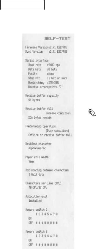
Self-test
Operation
The self-test can be run using the service utility or by operating the control panel. See page 2-12 for information about control panel operation.
Before running the self-test, make sure the roll paper and ribbon are installed correctly in the printer. Then, turn power off. To run the self-test, turn the power back on while holding down the FEED button.
The first page of the self-test printout should look like the example in the table below. To print the second part of the self-test, press FEED again.
2-2 Repair Guide |
Rev. B |
Confidential
TM-U220 Type A Service Manual
Printer Status Print
|
|
Normal printout result |
Explanation |
|
|
|
|
|
|
|
|
|
Version information |
|
|
|
|
Main program version |
|
|
|
|
Boot program version |
|
|
|
|
Interface classification |
|
|
|
Interface information |
||
|
|
|
||
|
|
|
Receive buffer capacity *1) |
|
|
|
|
Busy release conditions for receive buffer full *2) |
|
|
|
|
Busy condition *3) |
|
|
|
|
Resident character *4) |
|
|
|
|
7 Paper roll width *5) |
|
|
|
|
Dot spacing between characters *6) |
|
|
|
9 Characters per line *7) |
||
|
|
|
||
|
|
|
Autocutter unit installed/not installed *8) |
|
|
|
|
|
|
|
|
|
Note: |
|
|
|
|
*1) Differs depending on DIP SW1-2. |
|
|
|
|
*2) Differs depending on MSW 8-7. Prints only when the |
|
|
|
receive buffer capacity is 4KB. (Does not print when the |
||
|
|
|
receive buffer capacity is 40 bytes.) |
|
|
|
|
*3) Differs depending on DIP SW1-8. |
|
|
|
|
*4) Performs a multilingual CG judgment when printing resident |
|
|
|
|
characters. |
|
|
|
|
*5) Differs depending on the paper roll width set with the |
|
|
|
|
memory switch (customized value). |
|
|
7 |
|
*6) Differs depending on DIP SW2-1. |
|
|
|
*7) Differs depending on the paper roll width and dots |
||
|
|
|
||
|
|
|
between characters. |
|
|
|
|
*8) Differs depending on DIP SW2-2. |
|
|
|
|
|
|
|
9 |
|
|
|
|
|
|
|
|
|
|
|
|
|
Rev. B |
Repair Guide 2-3 |

Confidential
Roll Pattern
Normal print result |
Explanation |
Black (6 lines)
Red (6 lines)
 Red (6 lines)
Paper feeds 2 lines.
 Paper is fed to a position where the user can see the ending message at left.
2-4 Repair Guide |
Rev. B |
Confidential
TM-U220 Type A Service Manual
Service Utility
Using the service utility, you can confirm the printer status and change settings. The following section explains the operation for confirming the printer status.
*To use the repair functions in the service utility, a password is required. Refer to the manual supplied with the service utility for the password.
Start up of the service utility
When you start the service utility, the following communication conditions dialog box appears.
 1. Select the model (TM-U220).
 2. Select the type of I/F.
3. Select the parameters to communicate with the printer.
 4. Test the communication.
1.Model selection:
Select the TM-U220 (Type A model printer).
2.Communication condition selection:
Select the I/F used with the printer. You can confirm the communication conditions set for the printer by running the self-test. Refer to the self-test section for details.
3.Communication test:
4.Confirm the communication status with the connected printer. Normally, the following message appears.
.
When the communication conditions are set correctly, the following functions are available.
Self-test mode 1: Outputs the same results as the self-test printout of status.
Self-test mode 2: Outputs the same results as the self-test printout of the roll pattern.
Rev. B |
Repair Guide 2-5 |
Confidential
Real-time status: Lets you confirm sensor operations, such as cover open/close, in real time.
Printer status: Lets you read and set the printer values collectively. Also, you can save the settings to a file, read the set values in the file, and the display the default state. Refer to the chapter on adjustment settings.
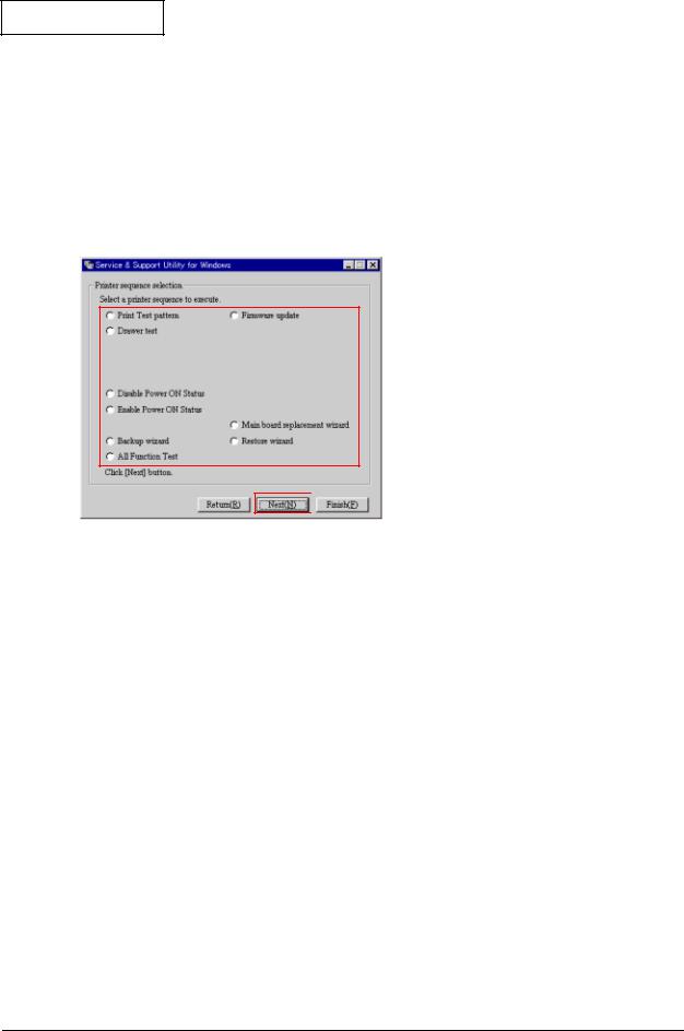
Printer sequence selection
When you click the Next button at the bottom of the communication conditions dialog box, the printer sequence selection screen appears.
 1. Select a printer sequence to execute.
 2. Click Next to proceed.
Test printing:
This outputs a test pattern to confirm printer status. Follow the screen instructions to operate.
Confirmation of the drawer operation:
You can confirm the drawer open function and the change in the open/close status. Follow the screen instructions to operate.
Setting for notification of power on:
You can enable or disable the notification function for power on.
Firmware update:
You can update the firmware. Follow the screen instructions to operate.
Main circuit board replacement wizard/backup wizard/restore wizard:
You can back up the data in the main circuit board and restore it in the repaired product. Follow the screen instructions to operate.
2-6 Repair Guide |
Rev. B |
Confidential
TM-U220 Type A Service Manual
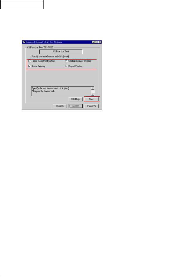
All Function Test
When you select the all function test in the printer sequence selection screen and click Next, the all function test screen appears.
 1. Select the test elements.
 2. Click to start the All Function Test.
Select the test elements and click the Start button to start the all function test.
Using this test, you can check the following functions for the printer.
Communication function:
You can confirm that communication with the printer is enabled/disabled.
Setting function:
Reads and prints on the status sheet the status settings for EPSON NV memory, memory switches, communication conditions, and customized value.
Receipt print function:
Prints patterns to confirm print operations and print quality.
Roll paper cut function:
The Type A model autocutter cuts roll paper after each printing on the roll.
Drawer open/close function:
Runs a test of drawer open/close operation while printing the receipt pattern. Be sure to connect the drawer kick to the printer before executing the all function test.
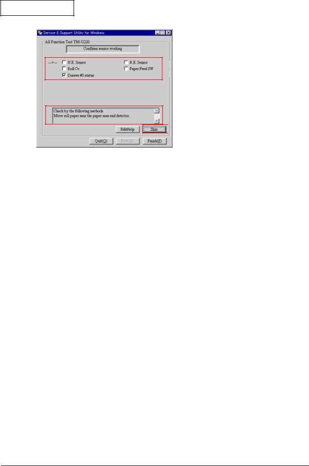
Sensor function:
Confirms the operation of sensors controlling and detecting printer operations. The checking method for the sensor indicated with the arrow is displayed on the screen. Operate the printer following the instructions on the screen.
Rev. B |
Repair Guide 2-7 |
Confidential
 1. Indicate the sensor to test.
 2. Follow the message to operate the printer.
 3. Click If you want to skip the test.
When the sensor detects the printer operation correctly, OK is displayed.
When the sensor is not installed (depending on the printer model), you can skip with the Skip button.
Test results are OK when the tests confirm the normal operation of the sensors.
2-8 Repair Guide |
Rev. B |

Confidential
TM-U220 Type A Service Manual
Output result
When the printer operates normally, the following sheet is printed. Refer to the chapters on “Troubleshooting” and “Adjustment and Setting” when print results differ.
Receipt Print
Normal print result |
Explanation |
|
|
|
Prints execution date. |
|
|
|
Prints execution time. |
|
Prints “EPSON/” |
|
Prints “TM-U220.” |
|
Prints product serial number. *1) |
|
Prints graphic pattern. Checks for missing dots. |
|
(See“Dots are missing continuously” on page 3-12.) |
|
Prints ANK characters. *2) |
|
Performs full cut. *3) |
|
|
Note: |
|
*1) |
When the serial number is not registered on the |
|
|
product itself, “NG” is printed. |
|
*2) |
When using the 2-color ribbon, prints in 2 colors. |
|
*3) |
When autocutter setting is partial cut, full cut is |
|
|
not performed. |
Rev. B |
Repair Guide 2-9 |

Confidential
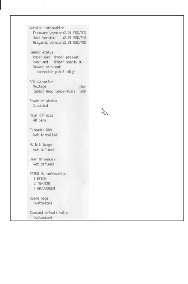
Status Print
Normal print result |
Explanation |
|
|
|
|
|
Prints execution date. |
|
|
||
|
Prints execution time. |
|
Prints “EPSON.” |
||
|
||
|
Prints “TM-U220.” |
|
Prints product serial number. *1) |
||
|
||
Prints setting status of memory switches. *2) |
||
|
||
|
Prints setting status of customize value. *3) |
|
|
Performs partial cut. *4) |
|
|
|
|
Note: |
|
*1) |
When the serial number is not registered on the |
|
|
product itself, “NG” is printed. |
|
*2, 3) When the default setting is changed, “*” is |
|
|
|
printed before the memory switch number. |
|
*4) |
When autocutter setting is full cut, partial cut is |
|
|
not performed. |
|
|
|
2-10 Repair Guide |
Rev. B |
Confidential
TM-U220 Type A Service Manual
Normal print result |
Explanation |
|
|
|
Prints program version. |
|
Main program version is printed. |
|
Boot program version is printed. |
|
Original program version is printed. |
|
Prints ”power on status” set with printer sequence. |
|
Displays size of main ROM. (Differs depending on |
|
specifications.) |
|
Displays size of extended ROM. (Differs depending |
|
on specifications.) |
|
Prints defined bit image data in NV memory. *1) |
|
Prints defined data in NV user memory. *2) |
|
Prints information on EPSON NV memory. It is |
|
changeable with the printer status. *3) |
|
Manufacturer name |
|
Model name |
|
Product serial no. |
|
Prints defined data for the space page. |
|
Prints definition of command default values. |
|
|
Note: |
|
*1, 2) Data defined by a user must be backed up |
||
|
||
|
and restored. |
|
|
|
|
|
|
|
|
|
|
|
|
Rev. B |
Repair Guide 2-11 |
Confidential
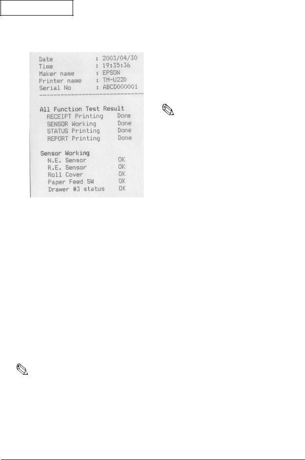
Report Print
Normal print result |
Explanation |
|
|
|
|
|
Prints execution date. |
|
Prints execution time. |
||
|
||
Prints “EPSON.” |
||
|
||
Prints “TM-U220.” |
||
|
||
Prints the serial number for the product. |
||
|
||
Prints the execution status of all function test. |
||
|
||
|
Prints test results of sensor operation. *1) |
|
|
Note: |
|
|
||
|
*1) When an operation such as cover open sensor |
|
|
check is skipped using the button on the screen, |
|
|
the report shows a problem for that item. (Refer |
|
|
to “Cannot pass one of the tests for a sensor” on |
|
|
page 3-18.) |
|
|
|
|
|
|
Running a Self-test
The steps below describe how to run a self-test by operating the control panel.
1.Make sure the printer is turned off and the roll paper cover is closed properly.
2.While holding down the FEED button, turn on the printer using the switch on the front of the printer. The self-test prints the printer settings and then prints the following, cuts the paper, and pauses. (The PAPER OUT light flashes.)
If you want to continue SELF-TEST printing, Please press the FEED button.
3.Press the FEED button to continue printing. The printer prints a pattern using the built-in character set.
4.The self test automatically ends and cuts the paper after printing the following:
***completed ***
5.The printer is ready to receive data as soon as it completes the self test.
Note:
If you want to pause the self-test manually, press the FEED button. Press the FEED button again to continue the self-test.
2-12 Repair Guide |
Rev. B |
Confidential
Chapter 3
TM-U220 Type A Service Manual
Troubleshooting
Preparations for Troubleshooting
Before troubleshooting, check and, if necessary, correct the following points.
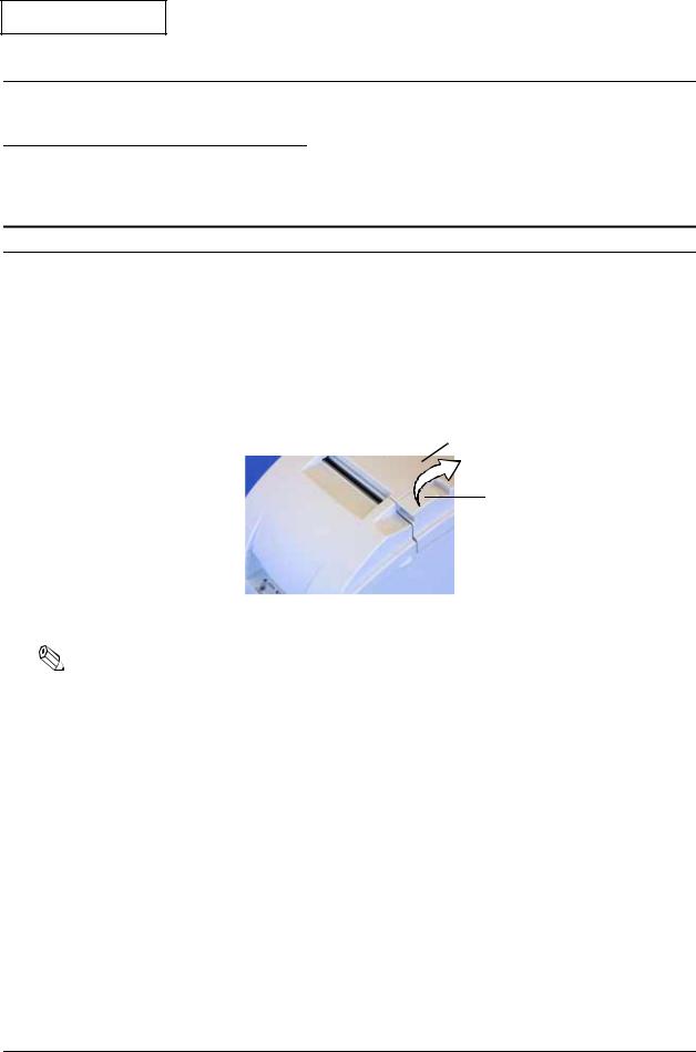
Paper is jammed inside the printer
 CAUTION:
Be sure not to touch the manual cutter. Otherwise, you may cut your fingers.
1.Turn the power off.
2.Open the roll paper cover using the tab, as shown in the below illustration.
Roll paper cover
Tab
3. Remove the jammed paper.
Note:
If you turn the power off accidentally during printing, the cutter blade may stop in the paper feed path. So, paper may not be fed normally at first when you turn the power on again. If the cutter blade does not return to the normal position, the autocutter unit may be jammed. If so, follow the procedure described below to repair the autocutter unit.
1.Power off the unit and open the roll paper cover.
2.Remove the jammed paper.
Rev. B |
Troubleshooting 3-1 |
Confidential
3.Return the cutter blade to the normal position by rotating the autocutter knob in the direction of the arrow. When the blade is returned to the normal position, the lever moves to the center of the hole in the autocutter frame.
Hole Lever
Autocutter unit
Knob
4. Lift up the roll paper cover.
Note:
Besides a paper jam, a foreign object, such as a push pin, can cause the autocutter to lock up. In this case, follow the same procedure described above to return the cutter to its normal position.
Before Servicing
Pages iv to v at the beginning of this manual provide precautions you should observe to perform work safely and supply the necessary information to service this product safely. Always read that information before starting your work.
Diagnosing Failures
Use one of the following methods to identify the area where a failure occurred.
See the tables in the section "Symptoms and Solutions" for diagnosing failures by the symptom of the problem.
See "Test Points on the Main Circuit Board Unit" for failures on the main circuit board unit.
3-2 Troubleshooting |
Rev. B |
Loading...