


Technical Reference Guide
Product Overview
Describes features for the product.
Setup
Describes setup and installation of the product and peripherals.
Application Development Information
Describes how to control the printer and necessary information when you develop applications.
Handling
Describes how to handle the product.
Appendix
Describes general specifications and character code tables.
M00075704
Rev. E

Cautions
•No part of this document may be reproduced, stored in a retrieval system, or transmitted in any form or by any means, electronic, mechanical, photocopying, recording, or otherwise, without the prior written permission of Seiko Epson Corporation.
•The contents of this document are subject to change without notice. Please contact us for the latest information.
•While every precaution has been taken in the preparation of this document, Seiko Epson Corporation assumes no responsibility for errors or omissions.
•Neither is any liability assumed for damages resulting from the use of the information contained herein.
•Neither Seiko Epson Corporation nor its affiliates shall be liable to the purchaser of this product or third parties for damages, losses, costs, or expenses incurred by the purchaser or third parties as a result of: accident, misuse, or abuse of this product or unauthorized modifications, repairs, or alterations to this product, or (excluding the U.S.) failure to strictly comply with Seiko Epson Corporation’s operating and maintenance instructions.
•Seiko Epson Corporation shall not be liable against any damages or problems arising from the use of any options or any consumable products other than those designated as Original Epson Products or Epson Approved Products by Seiko Epson Corporation.
Trademarks
EPSON is a registered trademark of Seiko Epson Corporation.
Exceed Your Vision and ESC/POS are registered trademarks or trademarks of Seiko Epson Corporation. Windows® is registered trademarks or trademarks of Microsoft Corporation in the United States and other countries.
microSD is registered trademarks of SD Card Association.
Wi-Fi®, WPATM, and WPA2TM are either registered trademarks or trademarks of Wi-Fi Alliance®. QR Code® is a registered trademark of DENSO Wave Incorporated.
AndroidTM is a trademark of Google Inc.
IOS® is a trademark or registered trademark of Cisco in the U.S. and other countries and is used under license.
All other trademarks are the property of their respective owners and used for identification purpose only.
ESC/POS® Command System
Epson ESC/POS is a proprietary POS printer command system that includes patented or patent-pending commands.
ESC/POS is compatible with most Epson POS printers and displays.
ESC/POS is designed to reduce the processing load on the host computer in POS environments. It comprises a set of highly functional and efficient commands and also offers the flexibility to easily make future upgrades.
© Seiko Epson Corporation 2014-2016. All rights reserved.
2
For Safety
Key to Symbols
The symbols in this manual are identified by their level of importance, as defined below. Read the
following carefully before handling the product.
You must follow warnings carefully to avoid serious bodily injury.
WARNING
|
Provides information that must be observed to prevent damage to the equipment or loss of data. |
|
|
Possibility of sustaining physical injuries. |
|
CAUTION |
|
Possibility of causing physical damage. |
|
|
Possibility of causing information loss. |
Provides information that must be observed to avoid damage to your equipment or a malfunction.
Provides important information and useful tips.
3

Warnings
To avoid risk of electric shock, do not set up this product or handle cables during a
thunderstorm
WARNING Never insert or disconnect the power plug with wet hands.
Doing so may result in electric shock.
Handle the power cable with care.
Improper handling may lead to fire or electric shock.
Do not modify or attempt to repair the cable.
Do not place any heavy object on top of the cable.
Avoid excessive bending, twisting, and pulling.
Do not place the cable near heating equipment.
Check that the plug is clean before plugging it in.
Be sure to push the plug all the way in.
Be sure to use the specified power source.
Connection to an improper power source may cause fire or electric shock.
Do not place multiple loads on the power outlet.
Overloading the outlet may lead to fire.
Shut down your equipment immediately if it produces smoke, a strange odor, or unusual noise.
Continued use may lead to fire. Immediately unplug the equipment and contact your dealer or a Seiko Epson service center for advice.
Never attempt to repair this product yourself.
Improper repair work can be dangerous.
Never disassemble or modify this product.
Tampering with this product may result in injury or fire.
Do not allow foreign matter to fall into the equipment.
Penetration by foreign objects may lead to fire.
If water or other liquid spills into this equipment, do not continue to use it.
Continued use may lead to fire. Unplug the power cord immediately and contact your dealer or a Seiko Epson service center for advice.
Do not use aerosol sprayers containing flammable gas inside or around this product.
Doing so may cause fire.
4

Cautions
Do not connect cables in ways other than those mentioned in this manual.
Different connections may cause equipment damage or fire.
CAUTION Be sure to set this equipment on a firm, stable, horizontal surface.
The product may break or cause injury if it falls.
Do not use this product in locations subject to high humidity or dust levels.
Excessive humidity and dust may cause equipment damage or fire.
Do not place heavy objects on top of this product. Never stand or lean on this product.
Equipment may fall or collapse, causing breakage and possible injury.
Take care not to injure your fingers on the manual cutter
When you remove printed paper
When you perform other operations such as loading/replacing roll paper
Do not open the roll paper cover without taking the necessary precautions, as this can result in injury from the autocutter fixed blade.
To ensure safety, unplug this product before leaving it unused for an extended period.
Do not knock or strike the printer. This may cause defective print.
Do not catch cables or place foreign matter under the printer.
Use the UL-approved peripherals (only for North American users).
Restriction of Use
When this product is used for applications requiring high reliability/safety, such as transportation devices related to aviation, rail, marine, automotive, etc.; disaster prevention devices; various safety devices, etc.; or functional/precision devices, etc., you should use this product only after giving consideration to including fail-safes and redundancies into your design to maintain safety and total system reliability. Because this product was not intended for use in applications requiring extremely high reliability/safety, such as aerospace equipment, main communication equipment, nuclear power control equipment, or medical equipment related to direct medical care, etc., please make your own judgment on this product's suitability after a full evaluation.
5

About this Manual
Aim of the Manual
This manual aims to provide all the information necessary for the development, design, and installment of POS systems, order entry systems, and other receipt issuing systems that use TM- T82II-i.
Manual Content
The manual is made up of the following sections:
Chapter 1 |
Product Overview |
Chapter 2 |
Setup |
Chapter 3 |
Application Development Information |
Chapter 4 |
Handling |
Appendix |
Product Specifications |
|
Option Specifications |
|
Setting Items for Software Setting Mode |
|
Character Code Tables |
6

Contents |
|
■ For Safety .............................................................................................................................. |
3 |
Key to Symbols ....................................................................................................................................... |
3 |
Warnings ................................................................................................................................................. |
4 |
Cautions.................................................................................................................................................. |
5 |
■ Restriction of Use .................................................................................................................. |
5 |
■ About this Manual................................................................................................................ |
6 |
Aim of the Manual................................................................................................................................. |
6 |
Manual Content .................................................................................................................................... |
6 |
■ Contents................................................................................................................................ |
7 |
Product Overview ........................................................................ |
11 |
■ Features............................................................................................................................... |
11 |
■ Product Configurations...................................................................................................... |
13 |
Bundled items....................................................................................................................................... |
13 |
Options.................................................................................................................................................. |
13 |
■ Part Names and Functions ................................................................................................ |
14 |
Power Switch ........................................................................................................................................ |
14 |
Power Switch Cover............................................................................................................................. |
14 |
Roll paper cover / Cover open lever................................................................................................. |
15 |
Cutter cover ......................................................................................................................................... |
15 |
Control Panel........................................................................................................................................ |
15 |
Interfaces .............................................................................................................................................. |
16 |
Status LED.............................................................................................................................................. |
17 |
Push Button ........................................................................................................................................... |
17 |
Wired LAN Status LED........................................................................................................................... |
18 |
Wireless LAN cable set (optional) LED ............................................................................................... |
18 |
■ Online and Offline .............................................................................................................. |
19 |
Online .................................................................................................................................................... |
19 |
Offline .................................................................................................................................................... |
19 |
■ Error Status........................................................................................................................... |
20 |
Automatically Recoverable Errors...................................................................................................... |
20 |
Recoverable Errors............................................................................................................................... |
20 |
Unrecoverable Errors ........................................................................................................................... |
21 |
■ NV Memory ........................................................................................................................ |
22 |
NV Graphics Memory.......................................................................................................................... |
22 |
Memory Switches (Customized Value).............................................................................................. |
22 |
R/E (Receipt Enhancement) .............................................................................................................. |
22 |
Maintenance Counter ........................................................................................................................ |
22 |
Setup ............................................................................................. |
23 |
■ Flow of Setup ...................................................................................................................... |
23 |
■ Installing the Product ......................................................................................................... |
28 |
Installing the Printer Vertically ............................................................................................................. |
29 |
7

Hanging the Printer on a Wall ............................................................................................................. |
30 |
■ Changing the Paper Width................................................................................................ |
32 |
■ Adjusting the Paper Roll Near-End Sensor ....................................................................... |
33 |
■ Installing the microSD Card............................................................................................... |
35 |
■ Connecting the Product to the Network .......................................................................... |
36 |
For Wired LAN connection .................................................................................................................. |
36 |
For Wireless LAN Interface ................................................................................................................... |
36 |
■ Connecting the Peripherals .............................................................................................. |
39 |
Connecting the Customer Display..................................................................................................... |
39 |
Connecting the Optional External Buzzer ......................................................................................... |
39 |
Connecting the Serial Communication Device ............................................................................... |
42 |
Key Input Device via a USB Interface................................................................................................. |
42 |
Connecting the Cash Drawer............................................................................................................. |
43 |
■ Connecting the AC Adapter............................................................................................. |
44 |
■ Attaching the Power Switch Cover ................................................................................... |
45 |
■ Setting the Memory Switches/Receipt Enhancement.................................................... |
46 |
Functions ............................................................................................................................................... |
48 |
■ Network Setting .................................................................................................................. |
57 |
Confirming Network Setting ................................................................................................................ |
59 |
Initializing the Network Setting ............................................................................................................ |
60 |
■ Enabling PHP....................................................................................................................... |
62 |
■ Enabling HTTPS Communication ....................................................................................... |
63 |
■ Settings for Server Direct Print ........................................................................................... |
64 |
■ Settings for Connected Devices ....................................................................................... |
65 |
■ Registering Web Contents ................................................................................................. |
67 |
Creating Web Contents ...................................................................................................................... |
67 |
Specifications for when PHP is enabled............................................................................................. |
68 |
Verifying the integrity of Web contents with md5 files ..................................................................... |
69 |
Certificate files ...................................................................................................................................... |
69 |
Registering Web Contents................................................................................................................... |
70 |
■ Settings for Spooler............................................................................................................. |
72 |
■ Settings for Print Forwarding .............................................................................................. |
73 |
■ Settings for Device Data Notification ............................................................................... |
74 |
Application Development Information...................................... |
75 |
■ Controlling the Printer ........................................................................................................ |
75 |
Epson ePOS SDK ................................................................................................................................... |
76 |
ePOS-Device XML................................................................................................................................. |
77 |
ePOS-Print XML...................................................................................................................................... |
79 |
Server Direct Print ................................................................................................................................. |
80 |
Device Data Notification..................................................................................................................... |
81 |
Web Server ............................................................................................................................................ |
82 |
Spooler and Print Forwarding.............................................................................................................. |
83 |
■ Software and Manuals....................................................................................................... |
86 |
How to Get Manuals and the Utility ................................................................................................... |
88 |
8

■ EPSON TMNet WebConfig .................................................................................................. |
89 |
Starting EPSON TMNet WebConfig ..................................................................................................... |
89 |
Help Screen Display ............................................................................................................................. |
89 |
Version Screen Display ......................................................................................................................... |
89 |
General Information............................................................................................................................. |
90 |
Information - Wired - TCP/IP ................................................................................................................ |
91 |
Information - Wireless - TCP/IP ............................................................................................................. |
91 |
Information - Web Contents................................................................................................................ |
92 |
Information - Time................................................................................................................................. |
92 |
Web Service Settings - Device Admin - Printer.................................................................................. |
93 |
Web Service Settings - Device Admin - Customer Display .............................................................. |
94 |
Web Service Settings - Device Admin - Key Input Device............................................................... |
95 |
Web Service Settings - Device Admin - Serial Communication Device ........................................ |
95 |
Web Service Settings - Device Admin - Search Printer .................................................................... |
96 |
Web Service Settings - Spooler - Settings........................................................................................... |
96 |
Web Service Settings - Spooler - Print forwarding ............................................................................. |
97 |
Web Service Settings - Web Contents - Update Settings................................................................. |
98 |
Web Service Settings - Server Access - Direct Print .......................................................................... |
99 |
Web Service Settings - Server Access - Status Notification............................................................ |
100 |
Web Service Settings - Server Access - Device Data Notification................................................ |
101 |
System Settings - Network - Wired .................................................................................................... |
102 |
System Settings - Network - Wired - TCP/IP ...................................................................................... |
102 |
System Settings - Network - Wireless ................................................................................................. |
103 |
System Settings - Network - Wireless - TCP/IP................................................................................... |
104 |
System Settings - Security - Authenticate Server............................................................................. |
104 |
System Settings - Security - SSL .......................................................................................................... |
105 |
System Settings - Proxy - Proxy........................................................................................................... |
106 |
System Settings - Time - Time ............................................................................................................. |
106 |
Admin Settings - Maintenance - Reset ............................................................................................ |
107 |
Admin Settings - Administrator Information - Administrator........................................................... |
107 |
Admin Settings - Administrator Information - Password.................................................................. |
107 |
PHP settings ......................................................................................................................................... |
108 |
■ Status sheet....................................................................................................................... |
109 |
■ Setting/Checking Modes ................................................................................................ |
115 |
Self-test Mode ..................................................................................................................................... |
115 |
NV Graphics Print Mode.................................................................................................................... |
116 |
Receipt Enhancement Information Print Mode.............................................................................. |
117 |
Software Setting Mode ...................................................................................................................... |
118 |
Hexadecimal Dumping Mode.......................................................................................................... |
121 |
■ Easy Setup......................................................................................................................... |
122 |
■ Checking/Updating TM-i Firmware ................................................................................ |
123 |
Checking the TM-i Firmware Version ................................................................................................ |
123 |
Updating TM-i Firmware ..................................................................................................................... |
123 |
Handling ..................................................................................... |
125 |
■ Installing and Replacing Roll Paper ............................................................................... |
125 |
■ Removing Jammed Paper .............................................................................................. |
127 |
■ Cleaning the Printer ......................................................................................................... |
128 |
Cleaning the Printer Case ................................................................................................................. |
128 |
Cleaning the Thermal Head.............................................................................................................. |
128 |
9

■ Preparing for Transport..................................................................................................... |
129 |
Appendix.................................................................................... |
131 |
■ Product Specifications..................................................................................................... |
131 |
Software Specifications ..................................................................................................................... |
132 |
Controllable Peripherals .................................................................................................................... |
133 |
Printing Specifications ........................................................................................................................ |
134 |
Character Specifications................................................................................................................... |
135 |
Printable Area..................................................................................................................................... |
139 |
Printing and Cutting Positions............................................................................................................ |
140 |
Paper Specifications .......................................................................................................................... |
140 |
Electrical Characteristics ................................................................................................................... |
141 |
Environmental Conditions.................................................................................................................. |
142 |
External Dimensions and Mass.......................................................................................................... |
143 |
AC Adapter......................................................................................................................................... |
144 |
■ Option Specifications ...................................................................................................... |
144 |
Wireless LAN Cable Set (OT-WL01).................................................................................................... |
144 |
Customer Display (DM-D110) ............................................................................................................ |
144 |
■ Setting Items for Software Setting Mode ........................................................................ |
145 |
■ Character Code Tables ................................................................................................... |
148 |
10
Chapter 1 Product Overview 
Product Overview
This chapter describes features of the product.
Features
TM-T82II-i is a receipt printer which can print directly from a smart device application or Web application.
This product supports ePOS-Device *1 and ePOS-Print *2 and are capable of controlling POS
peripherals or network compatible TM printers. 1
*1: ePOS-Device: Epson original technology to control TM printers or POS peripherals via a smart device application or Web application. This technology is realized by ePOS-Device Service running on the products.
*2: ePOS-Print: Epson original printing function that has a high compatibility with a variety of systems supported by XML and Web services. This technology is realized by the ePOS-Print
Service running on the products.
11

Functions
•Enables connection to peripherals (customer displays, barcode scanners, etc) via a USB or serial interface.
•The Epson ePOS SDK is provided for iOS, Android and Windows application, and Web application development.
The Epson ePOS SDK is a software development kit that integrates the ePOS-Print SDK and the ePOS-Device SDK. It is recommended that application software developed with the ePOS-Device SDK is migrated to the Epson ePOS SDK. For detail, refer to the Migration Guide included with the Epson ePOS SDK.
•Uses the communication box *1 function to enable communications between applications. This function allows for communications, etc. between tablet terminals. (ePOS-Device SDK, ePOS-Device XML)
•Supports Server Direct Print that sends a request for print data from the product to the Web server at regular intervals.
•Since print data can be saved in the spooler, applications can be released from processing print jobs regardless of the printer status. *2
•When a network printer is registered, print forwarding process can be realized. Also, if the printer is not ready to print, you can print from another printer. *2
•Device data notification function is realized, allowing for notifications to be sent from devices such as barcode scanners to Web servers to trigger applications. *2
•Equipped with Web server that supports the scripting language "PHP" and database "SQLite3".
•Enables HTTPS *3 communication.
•Supports TLS 1.2. SSL3.0 is not supported. *4
*1: For more information on the communication box, see the ePOS-Device SDK for iOS User's Manual, the ePOS-Device SDK for Android User's Manual, the ePOS-Device SDK for JavaScript
User's Manual, and the ePOS-Device XML User's Manual. *2: TM-i firmware Ver. 4.1 or later.
*3: TM-i firmware Ver. 4.3 or later. *4: TM-i firmware Ver. 4.4 or later.
For information on how to use these functions, see "Controlling the Printer" on page 75.
12

Chapter 1 |
Product Overview |
|
|
|
|
|
|
|
|
Product Configurations |
|
|
|
|
Bundled items |
|
|
|
|
• AC adapter |
|
|
|
|
• AC cable * |
|
|
|
|
• Roll paper (for operation check) |
|
|
|
|
• Roll paper guide for 58 mm width paper |
|
|
|
|
|
|
|
|
|
• Start Here |
|
|
1 |
|
• Manual CD |
|
|||
•Power switch cover
•Waterproof power switch cover
•Wall-hanging bracket
•Screws for installing the wall-hanging bracket
•Rubber feet for vertical installation
•Switch panel for vertical installation
*May not be included depending on the areas and models.
Options
•Affixing tape for fixing the printer (Model: DF-10)
•Buzzer unit (Model: OT-BZ20)
•Wireless LAN cable set (Model: OT-WL01)
•Customer display (Model: DM-D110)
13
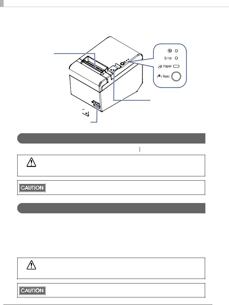
Part Names and Functions
Control panel
Roll paper cover  Manual cutter
Cutter cover 
Cover open lever
Power switch cover 


Power switch
Power Switch
Turns the printer on or off. The marks on the switch: (  : OFF/ : ON)
Before turning on the product, be sure to check that the AC adapter is connected to the power supply.
CAUTION
After the product is turned on, it requires about 30 seconds until it is ready to print.
Power Switch Cover
Install the power switch cover that comes with the TM-T82II-i onto the printer to prevent inadvertent changing of the power switch, to prevent tampering, and to improve the appearance of the printer.
To operate the power switch, insert an object with a pointed tip such as a ballpoint pen into the hole on the power switch cover.
A waterproof cover for the power switch is also included.
If an accident occurs with the power switch cover attached, unplug the power cord immediately.
WARNING Continued use of the printer may cause fire or electric shock.
Use the waterproof power switch cover if the printer is installed in a humid location or exposed to water. If current leakage occurs, it could result in electric shock.
14
Chapter 1 Product Overview 
Roll paper cover / Cover open lever
When setting or replacing the roll paper, use the cover open lever to open the roll paper cover.
Do not open the roll paper cover during printing or while the autocutter is operating.
Cutter cover
The autocutter is inside the cutter cover. Open the cover when roll paper is jammed in the printer or
to return the cutter blade manually. |
1 |
|
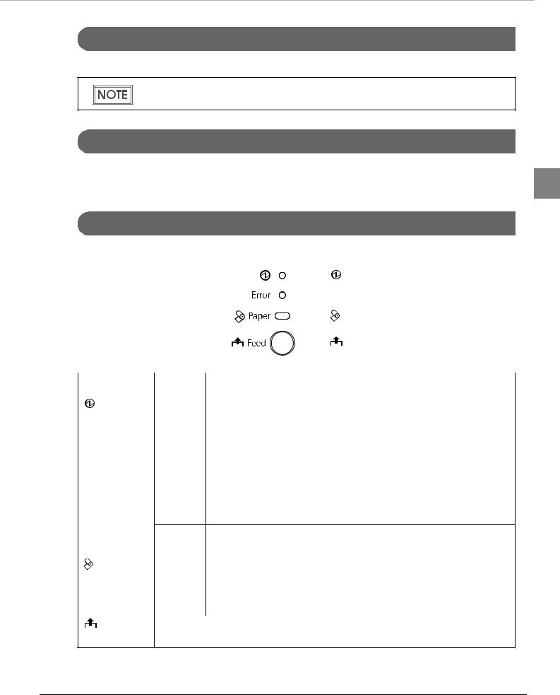
Control Panel
|
|
|
|
|
|
|
|
|
(Power) LED |
|
|
|
|
|
|
|
|||
|
|
|
|
|
|
|
|
|
Error LED |
|
|
|
|
|
|
|
|
||
|
|
|
|
|
|
|
|
|
Paper LED |
|
|
|
|
|
|
||||
|
|
|
|
|
|
|
|
|
|
|
|
|
|
|
|
|
|
|
Feed button |
|
|
|
|
|
|
|
|
|
|
|
|
|
|
|
|
|
|
|
|
Name |
Status |
|
|
|
|
|
|
|
Description |
|
|
|
|
|
|
|
|
|
|
(Power) LED |
On |
Power is being supplied. |
|||||||
|
|
|
|
|
|
|
|
|
|
|
Off |
Power is not being supplied. |
|||||||
|
|
|
|
|
|
|
|
|
|
Error LED |
Off |
Normal operation (online) |
|||||||
|
|
|
|
|
|
|
|
|
|
|
On |
Immediately after the power is turned on or immediately after a reset |
|||||||
|
|
(offline). |
|||||||
|
|
Automatically goes off after a while to indicate that the printer is ready. |
|||||||
The end of the roll paper is detected, and when printing has stopped (offline). If this happens, replace the roll paper.
|
Flashing |
An error has occurred |
|
|
(For details about the flash codes, see "Error Status" on page 20.) |
|
|
|
Paper LED |
Off |
There is a sufficient amount of roll paper remaining. |
|
|
|
|
On |
There is little or no roll paper remaining. |
|
|
|
|
Flashing |
A self-test printing standby state and macro execution standby state |
|
|
|
Feed button |
Pressing this button once feeds the roll paper by one line. Holding this button down |
|
|
feeds the roll paper continuously. |
|
15
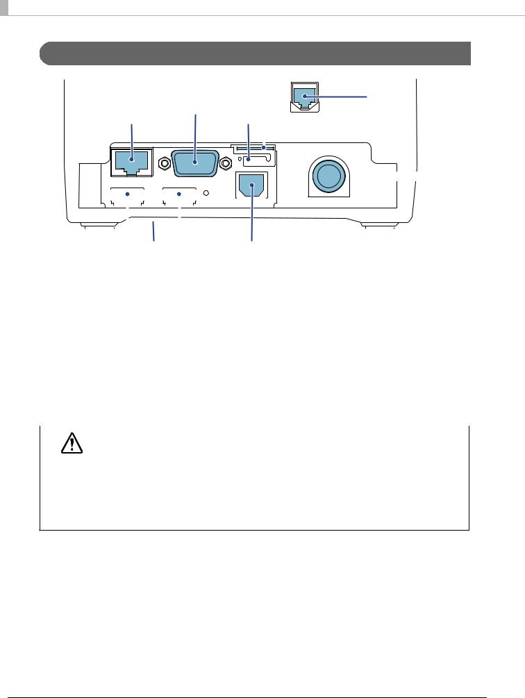
Interfaces
Serial port
Ethernet port
Drawer kick |
connector |
Protective cover
 micro SD card slot
 DC-in connector
|
|
|
|
|
|
|
|
|
|
|
|
|
|
|
|
|
|
|
|
|
|
|
|
|
|
|
|
|
|
|
|
|
|
|
|
|
|
|
|
|
|
|
|
|
|
|
|
|
|
|
|
|
|
|
|
|
|
|
|
|
|
|
|
|
|
|
|
|
|
|
|
|
|
|
|
|
|
|
|
|
|
|
|
|
|
|
|
|
|
|
|
|
|
|
|
|
|
|
|
|
|
|
|
|
|
|
|
|
|
|
|
|
|
|
|
|
|
|
|
|
|
|
|
|
|
|
|
|
|
|
|
|
|
|
|
|
|
|
|
|
|
|
|
|
|
|
|
USB host ports |
|
|
|
|
|
|
|
|
|||||
|
|
|
|
USB device port |
|||||||||||||
|
|
|
|
|
|
|
|
|
|
|
|
|
|
|
|
|
|
|
Name |
|
|
|
|
|
Description |
||||||||||
|
|
|
|
|
|
|
|
|
|
|
|
|
|
|
|
|
|
Drawer kick connector |
Connects a cash drawer or the optional buzzer unit. |
||||||||||||||||
|
|
|
|
|
|
|
|
|
|
|
|
|
|
|
|
|
|
Ethernet port |
|
|
|
|
|
Connect the LAN cable here to connect to the network. |
|||||||||||
|
|
|
|
|
|
|
|
|
|
|
|
|
|
|
|
|
|
USB host port (Type A) |
Connects peripherals via a USB interface. |
||||||||||||||||
|
|
|
|
|
|
|
|
|
|
|
|
|
|
|
|
|
|
USB device port (Type B) |
Connects a computer when setting the product with TM-T82II Utility. |
||||||||||||||||
|
|
|
|
|
|
|
|
|
|
|
|
|
|
|
|
|
|
DC-In connector |
|
|
|
|
|
Connects a AC adapter. |
|||||||||||
|
|
|
|
|
|
|
|
|
|
|
|
|
|
|
|
|
|
microSD card slot |
Used when using the PHP function. |
||||||||||||||||
|
|
|
|
|
|
|
|
|
|
|
|
|
|
|
|
|
|
Serial port |
|
|
|
|
|
Connects a serial communication device. |
|||||||||||
|
|
|
|
|
|
|
|
|
|
|
|
|
|
|
|
|
|
|
|
|
|
|
|
|
|
|
|
|
|
|
|
|
|
|
|
|
|
|
When connecting USB interface devices, make sure to check the devices or manuals, |
||||||||||||||
|
|
|
|
etc. for current consumption. The total value should be 800 mA or less. Never use |
|||||||||||||
CAUTION |
|
devices that provide no information on current consumption. |
|||||||||||||||
Make sure that the protective cover is securely fit into place while the product is oper- |
|||||||||||||||||
ating.
For Ethernet ports, make sure that the outdoor aerial LAN cables are connected through a surge protector. Failure to do so may lead to device error resulting from indirect lightning.
16

Chapter 1 Product Overview 
Status LED
With the status LED on the rear of the product, you can check the interface board status.
Status LED |
LED |
Description |
|
|
|
|
|
1 |
On (Green) |
Operating normally. |
|
|
|
|
||
|
|
|
|
On (Orange) |
Starting up. |
|
|
|
If the status LED is on in orange even after 30 seconds have passed since the |
|
|
|
printer is turned on, repair is required. |
|
|
|
|
|
|
Off |
Power is not turned on. |
|
|
|
If the status LED is off even if the printer is turned on, repair is required. |
|
|
|
|
|
|
Push Button
Push button
Press the push button with a thin object such as a tweezers.
The push button has the following functions:
•Status sheet printing:
Make sure the product is turned on, press the push button for approximately 3 seconds. When you release the button, a status sheet on which network parameters are printed will be ejected. (See "Confirming with a status sheet" on page 59.)
•Initialization:
Make sure the product is turned on, press the push button for approximately 10 seconds. When you release the button, network setting (Wired LAN/ Wireless LAN) will be initialized. (See "Initializing the Network Setting" on page 60.)
To print a status sheet, release the push button within 10 seconds. If the button is kept down for 10 seconds or more, the network setting will be initialized.
Press the push button after the status LED color has changed from orange to green. After the printer is turned on, it takes about 20 to 30 seconds until the status LED color changes to green.
Even if the button is pressed while the status LED is on in orange, the button will not operate.
17

Wired LAN Status LED
With the Wired LAN Status LED on the rear of the product, you can check the communication status
of the product.
|
|
|
|
|
|
|
|
|
|
|
|
|
|
|
|
|
|
|
|
|
LED (Green) |
|
|
|
|
|
|
|
|
|
|
|
|
|
|
|
|
|
|
|
|
|
|
|
|
|
|
|
|
|
|
|
|
|
|
|
|
|
|
|
|
|
|
|
LED (Yellow) |
|
|
|
|
|
|
|
|
|
|
|
|
|
|
|
|
|
|
|
|
|
|
|
|
|
|
|
|
|
|
|
|
|
|
|
|
|
|
|
|
|
|
|
|
|
|
|
|
|
|
|
|
|
|
|
|
|
|
|
|
|
|
|
|
|
|
|
|
|
|
|
|
|
|
|
|
|
|
|
|
|
|
|
|
|
|
|
|
|
|
|
|
|
|
|
|
|
|
|
|
|
|
|
|
|
|
|
|
|
|
LED |
Status |
|
|
|
|
|
|
|
|
|
|
|
|
|
|
Description |
|||||
|
|
|
|
|
|
|
|
|
|
|
|
|
|
|
|
|
|
|
|
|
|
Green |
On |
|
|
Link established |
|||||||||||||||||
|
|
|
|
|
|
|
|
|
|
|
|
|
|
|
|
|
|
|
|
|
|
|
Flashing |
|
|
Transmitting/receiving data |
|||||||||||||||||
|
|
|
|
|
|
|
|
|
|
|
|
|
|
|
|
|
|
|
|
|
|
|
Off |
|
|
Link not established |
|||||||||||||||||
|
|
|
|
|
|
|
|
|
|
|
|
|
|
|
|
|
|
|
|
|
|
Yellow |
On |
|
|
100BASE-TX |
|||||||||||||||||
|
|
|
|
|
|
|
|
|
|
|
|
|
|
|
|
|
|
|
|
|
|
|
Off |
|
|
10BASE-T |
|||||||||||||||||
|
|
|
|
|
|
|
|
|
|
|
|
|
|
|
|
|
|
|
|
|
|
Wireless LAN cable set (optional) LED
With the LED on the wireless LAN unit, you can check the communication status of the product.
|
|
|
LED (Green) |
|
|
|
|
||
|
|
|
|
|
LED |
|
Description |
||
|
|
|
|
|
Off |
The wireless LAN unit is not connected to the product. Or the product power is OFF. |
|||
|
|
|
|
|
Flashing |
This wireless LAN unit is connected to the product and is in operation. |
|||
|
|
|
|
|
Flashing rapidly |
This wireless LAN unit is connected to the product and is in operation. |
|||
This unit is communicating on a network. |
||||
|
||||
|
|
|
|
|
18

Chapter 1 Product Overview 
Online and Offline
Online
When no events to go offline have occurred, the printer is online and ready for normal printing.
Offline
The printer automatically goes offline under the following conditions: |
1 |
• During power on (including resetting with the interface) until the printer is ready |
•During the self-test
•When the roll paper cover is open.
•While roll paper is fed using the Feed button.
•When printing stops due to end of paper. (When the roll paper end sensor detects the end of paper or the printer is set so that printing stops upon detection of roll paper near-end.)
•Macro execution standby state
•When an error has occurred
19

Error Status
There are three possible error types: automatically recoverable errors, recoverable errors, and unrecoverable errors. Check the error LED flash code.
When connection to peripherals fails, check the status LEDs at the lower rear of the product.
Automatically Recoverable Errors
Printing is no longer possible when automatically recoverable errors occur. They can be recovered
easily, as described below.
Error |
Error description |
Error LED flash code |
Recovery measure |
|||||||||||||||||||||||
|
|
|
|
|
|
|
|
|
|
|
|
|
|
|
|
|
|
|
|
|
|
|
|
|
|
|
Roll paper cover |
The roll paper cover was |
LED ON |
|
|
|
|
|
|
|
|
|
|
|
|
|
|
|
|
|
|
|
|
|
|
Recovers automatically |
|
open error |
opened during printing. |
|
|
|
|
|
|
|
|
|
|
|
|
|
|
|
|
|
|
|
|
|
|
when the roll paper |
||
LED OFF |
|
|
|
|
|
|
|
|
|
|
|
|
|
|
|
|
|
|
|
|
|
|
|
|||
|
|
|
|
|
|
|
|
|
|
Approx. 160 ms |
|
|
|
|
|
cover is closed. |
||||||||||
|
|
|
|
|
|
|
|
|
|
|
|
|||||||||||||||
|
|
|
|
|
|
|
|
|
|
|
|
|
|
|
|
|
|
|
|
|
|
|
|
|
|
|
|
|
|
|
|
|
|
|
|
|
|
|
|
|
|
|
|
|
|
|
|
|
|
|
|
|
|
Print head |
A high temperature |
|
|
|
|
|
|
|
|
|
|
|
|
|
|
|
|
|
|
|
|
|
|
|
|
Recovers automatically |
temperature |
outside the head drive |
LED ON |
|
|
|
|
|
|
|
|
|
when the print head |
||||||||||||||
|
|
|
|
|
|
|
|
|
|
|
|
|
|
|
|
|
|
|
|
|
|
|||||
error |
operating range was |
LED OFF |
|
|
|
|
|
|
|
|
|
|
|
|
|
|
|
|
|
|
|
cools. |
||||
|
|
|
|
|
|
|
|
Approx. 160 ms |
|
|
|
|
|
|
|
|
|
|||||||||
|
detected. |
|
|
|
|
|
|
|
|
|
|
|
|
|
||||||||||||
|
|
|
|
|
|
|
|
|
|
|
|
|
|
|
|
|
|
|
|
|
|
|
|
|
|
|
|
|
|
|
|
|
|
|
|
|
|
|
|
|
|
|
|
|
|
|
|
|
|
|
|
|
|
Recoverable Errors
Printing is no longer possible when recoverable errors occur. They can be recovered easily by turning
the power on again after eliminating the cause of the error.
Error |
Error description |
Error LED flash code |
Recovery measure |
||||||||
|
|
|
|
|
|
|
|
|
|
|
|
Autocutter error |
Autocutter does not |
|
|
|
|
|
|
|
|
|
Remove the jammed |
|
work correctly. |
LED ON |
paper or foreign matter in |
||||||||
|
|
the printer, close the roll |
|||||||||
|
|
LED OFF |
|||||||||
|
|
paper cover, and then |
|||||||||
|
|
Approx. 160 ms |
|
|
|
|
|
Approx. 2560 ms |
|
|
|
|
|
|
|
||||||||
|
|
|
|
|
|
|
|
|
|
turn the power on to |
|
|
|
|
|
|
|
|
|
|
|||
|
|
|
|
|
|
|
|
|
|
|
|
|
|
|
|
|
|
|
|
|
|
|
recover. |
|
|
|
|
|
|
|
|
|
|
|
|
20
Chapter 1 Product Overview 
Unrecoverable Errors
If the same error occurs again even after turning the power back on, contact your dealer or a Epson
service center.
Turn off the power immediately when unrecoverable errors occur.
CAUTION
Error |
Error description |
Error LED flash code |
|
|
|||||||||||||||||||||||||||||||||||||||||||
|
|
|
|
|
|
|
|
|
|
|
|
|
|
|
|
|
|
|
|
|
|
|
|
|
|
|
|
|
|
|
|
|
|
|
|
|
|
|
|
|
|
|
|
|
|
|
|
|
|
|
|
|
|
|
|
|
|
|
|
|
|
|
|
|
|
|
|
|
|
|
|
|
|
|
|
|
|
|
|
|
|
|
|
|
|
|
|
|
|
|
|
|
|
|
1 |
Memory R/W error |
After R/W checking, the printer does not |
LED ON |
|
|
|
|
|
|
|
|
|
|
|
|
|
|
|
|
|
|
|
|
|
|
|
|
|
|
|
|
|
|
|
|
|
|
|
|
|||||||||
|
work correctly. |
LED OFF |
|
|
|
|
|
|
|
|
|
|
|
|
|
|
|
|
|
|
|
Approx. 160 ms |
|
|
|
|
|
|
|
|
|
|
|
|
|
|
|
|
|||||||||
|
|
|
|
|
|
|
|
|
|
|
|
|
|
|
|
|
|
|
|
|
|
|
|
|
|
|
|
|
|
|
|
|
|
|
|
||||||||||||
|
|
|
|
|
|
|
|
|
|
|
|
|
|
|
|
|
|
|
|
|
|
|
|
|
|
|
|
|
|
|
|
|
|
|
|
|
|
|
|
|
|
||||||
|
|
|
|
|
|
|
|
|
|
|
|
|
|
|
|
|
|
|
|
|
|
|
|
|
|
|
|
||||||||||||||||||||
|
|
|
|
|
|
|
|
|
|
|
|
|
|
|
|
|
|
|
|
|
|
|
|
|
|
|
|
|
|
|
|
|
|
|
|
|
|
|
|
|
|
|
|
|
|
|
|
High voltage error |
The power supply voltage is extremely high. |
LED ON |
|
|
|
|
|
|
|
|
|
|
|
|
|
|
|
|
|
|
|
|
|
|
|
|
|
|
|
|
|
|
|
|
|
|
|||||||||||
|
|
LED OFF |
|
|
|
|
|
|
|
|
|
|
|
|
|
|
|
|
|
|
|
Approx. 160 ms |
|
|
|
|
|
|
|
|
|
|
|
|
|
|
|||||||||||
|
|
|
|
|
|
|
|
|
|
|
|
|
|
|
|
|
|
|
|
|
|
|
|
|
|
|
|
|
|
|
|
|
|
|
|
|
|
|
|||||||||
|
|
|
|
|
|
|
|
|
|
|
|
|
|
|
|
|
|
|
|
|
|
|
|
|
|
|
|
|
|||||||||||||||||||
|
|
|
|
|
|
|
|
|
|
|
|
|
|
|
|
|
|
|
|
|
|
|
|
|
|
|
|
|
|
|
|
|
|
|
|
|
|
|
|
|
|
|
|
|
|
|
|
Low voltage error |
The power supply voltage is extremely low. |
LED ON |
|
|
|
|
|
|
|
|
|
|
|
|
|
|
|
|
|
|
|
|
|
|
|
|
|
|
|
|
|
||||||||||||||||
|
|
LED OFF |
|
|
|
|
|
|
|
|
|
|
|
|
|
|
|
|
|
Approx. 160 ms |
|
|
|
|
|
|
|
|
|
|
|
|
|||||||||||||||
|
|
|
|
|
|
|
|
|
|
|
|
|
|
|
|
|
|
|
|
|
|
|
|
|
|
|
|
|
|
|
|
|
|
|
|
|
|||||||||||
|
|
|
|
|
|
|
|
|
|
|
|
|
|
|
|
|
|
|
|
|
|
|
|
|
|
|
|
|
|
|
|||||||||||||||||
|
|
|
|
|
|
|
|
|
|
|
|
|
|
|
|
|
|
|
|
|
|
|
|
|
|
|
|
|
|
|
|
|
|
|
|
|
|
|
|
|
|
|
|
|
|
|
|
CPU execution error |
The CPU is executing an incorrect address. |
LED ON |
|
|
|
|
|
|
|
|
|
|
|
|
|
|
|
|
|
|
|
|
|
|
|
|
|
||||||||||||||||||||
|
|
LED OFF |
|
|
|
|
|
|
|
|
|
|
|
|
|
|
|
|
|
|
|
|
|
|
|
|
|
|
|
||||||||||||||||||
|
|
|
|
|
|
|
|
|
|
|
|
|
|
|
|
|
|
|
|
|
|
|
|
|
|
Approx. 160 ms |
|
|
|
|
|
|
|
|
|
||||||||||||
|
|
|
|
|
|
|
|
|
|
|
|
|
|
|
|
|
|
|
|
|
|
|
|
|
|
|
|
|
|
|
|
|
|||||||||||||||
|
|
|
|
|
|
|
|
|
|
|
|
|
|
|
|
|
|
|
|
|
|
|
|
|
|
|
|
|
|
|
|
|
|
|
|
|
|
|
|
|
|
|
|
|
|
|
|
Internal circuit |
Internal circuits are not connected correctly. |
LED ON |
|
|
|
|
|
|
|
|
|
|
|
|
|||||||||||||||||||||||||||||||||
connection error |
|
LED OFF |
|
|
|
|
|
|
|
|
|
|
|
|
|
||||||||||||||||||||||||||||||||
|
|
|
|
|
|
|
|
|
|
|
|
|
|
||||||||||||||||||||||||||||||||||
|
|
Approx. 160 ms |
|
|
|
|
|
|
|
|
|
|
|||||||||||||||||||||||||||||||||||
|
|
|
|
|
|
||||||||||||||||||||||||||||||||||||||||||
|
|
|
|
|
|
|
|
|
|
|
|
|
|
|
|
|
|
|
Approx. 2560 ms |
|
|
|
|
||||||||||||||||||||||||
|
|
|
|
|
|
|
|
|
|
|
|
|
|
|
|
|
|
|
|
|
|
||||||||||||||||||||||||||
|
|
|
|
|
|
|
|
|
|
|
|
|
|
|
|
|
|
|
|
|
|
|
|
|
|
|
|
|
|
|
|
|
|
|
|
|
|
|
|
|
|
|
|
|
|
|
|
21
NV Memory
The product's NV memory (Non-Volatile Memory) stores data even after the product power is turned off. NV memory contains the following memory areas for the user:
•NV graphics memory
•Memory switches (customized value)
•R/E (Receipt Enhancement)
•Maintenance counter
As a guide, NV memory rewriting should be 10 times or less a day when you program applications.
CAUTION
NV Graphics Memory
Graphics, such as shop logos to be printed on receipts, can be stored.
Use the TM-T82II Utility to register graphics.
To check the registered graphics, select [Operation Check] - [Print Logo] in TM-T82II Utility.
For detailed information about the TM-T82II Utility, see the TM-T82II Utility User’s Manual.For information about how to use the NV graphics memory print mode, see "NV Graphics
Print Mode" on page 116.
Memory Switches (Customized Value)
With the memory switches (customized value), which are software switches for the product, you can set paper width, print density, font, power supply unit capacity, automatic paper cut, and paper reduction. See "Setting the Memory Switches/Receipt Enhancement" on page 46.
R/E (Receipt Enhancement)
Graphics, such as shop logos can be printed on top or bottom of receipts by setting R/E (Receipt
Enhancement). For information about R/E, see "Setting the Memory Switches/Receipt
Enhancement" on page 46.
Maintenance Counter
With this function, printer information, such as the number of line feeds, the number of autocuts and product operation time after the printer starts working, is automatically stored in NV memory. You can read the information with the TM-T82II Utility or in a self-test to use it for periodical checks or part replacement.
22

Chapter 2 Setup
Setup
This chapter describes the installation and setup procedure of the product and peripherals required to use the product.
You can utilize "Easy Setup", which enables settings to the TM-i to be made in a simple manner using a USB memory that contains a file of EPSON TMNet WebConfig setting values.
For detail, refer the “TM-i series Easy Setup Guide”.
Flow of Setup
The setting items are different depending on the system to be used. Check the items by referring to |
|
|
"Controlling the Printer" on page 75. |
|
|
• Epson ePOS SDK, ePOS-Device XML, ePOS-Print XML (page 24) |
|
|
2 |
||
• Server Direct Print (page 25) |
||
|
||
• Device Data Notification (page 26) |
|
|
|
||
• Using This Product as a Web Server (page 27) |
|
|
This chapter consists of the following sections along with the setup flow of the product and |
|
|
peripherals. |
|
In this setup flow, necessary items are in a frame with a solid line. Optional items are explained in an frame with a dotted line.
23

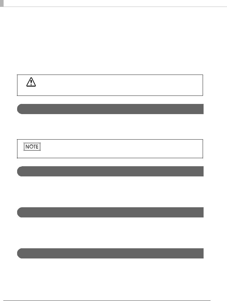
Epson ePOS SDK, ePOS-Device XML, ePOS-Print XML
Settings for Printer
1.Installing the Product (page 28)
2.Changing the Paper Width (page 32)
3.Adjusting the Paper Roll Near-End Sensor (page 33)
4.Connecting the Peripherals (page 39)
5.Connecting the Product to the Network (page 36)
6.Connecting the AC Adapter (page 44)
7.Attaching the Power Switch Cover (page 45)
8.Setting the Memory Switches/Receipt Enhancement (page 46)
Settings for EPSON TMNet WebConfig
9. Network Setting (page 57)
10.Enabling HTTPS Communication (page 63)
11.Settings for Connected Devices (page 65)
12.Settings for Spooler (page 72)
13.Settings for Print Forwarding (page 73)
24
Chapter 2 Setup
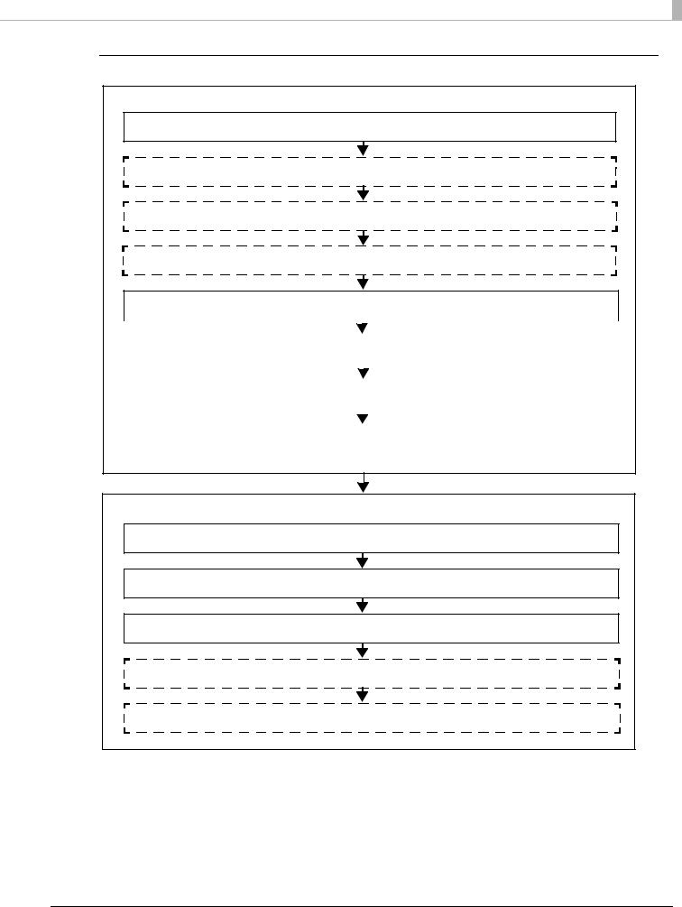
Server Direct Print
Settings for Printer
1. Installing the Product (page 28)
2. Changing the Paper Width (page 32)
3.Adjusting the Paper Roll Near-End Sensor (page 33)
4.Connecting the Peripherals (page 39)
5.Connecting the Product to the Network (page 36)
|
|
|
|
|
|
|
|
|
|
|
|
|
|
|
|
|
|
|
|
|
|
|
|
|
|
|
|
|
|
|
|
|
|
|
|
|
|
|
|
|
|
|
|
|
|
|
|
|
|
|
|
|
|
|
|
|
|
|
|
|
|
|
|
|
|
|
|
2 |
|
|
|
|
|
|
|
|
|
|
|
|
|
|
|
|
|
|
|
|
|
|
|
|
|
|
|
|
|
|
|
|
|
|
|
|
|
|
|
|
|
|
|
|
|
|
|
|
|
|
|
|
|
|
|
|
|
|
|
|
|
|
|
|
|
|
|
|
|
|
|
|
6. Connecting the AC Adapter (page 44) |
|
|
|
|
|||||||||||||||||||||||||||||||||||||||||||||||||||||||||||||
|
|
|
|
|
|
|
|
|||||||||||||||||||||||||||||||||||||||||||||||||||||||||||||
|
|
|
|
|
|
|
|
|
|
|
|
|
|
|
|
|
|
|
|
|
|
|
|
|
|
|
|
|
|
|
|
|
|
|
|
|
|
|
|
|
|
|
|
|
|
|
|
|
|
|
|
|
|
|
|
|
|
|
|
|
|
|
|
|
|
|
|
|
|
|
|
|
|
|
|
|
|
|
|
|
|
|
|
|
|
|
|
|
|
|
|
|
|
|
|
|
|
|
|
|
|
|
|
|
|
|
|
|
|
|
|
|
|
|
|
|
|
|
|
|
|
|
|
|
|
|
|
|
|
|
|
|
|
|
|
|
|
|
|
|
7. Attaching the Power Switch Cover (page 45) |
|
|
|
|
|
||||||||||||||||||||||||||||||||||||||||||||||||||||||||||||
|
|
|
|
|||||||||||||||||||||||||||||||||||||||||||||||||||||||||||||||||
|
|
|
|
|
|
|
|
|||||||||||||||||||||||||||||||||||||||||||||||||||||||||||||
|
|
|
|
|
|
|
|
|
|
|
|
|
|
|
|
|
|
|
|
|
|
|
|
|
|
|
|
|
|
|
|
|
|
|
|
|
|
|
|
|
|
|
|
|
|
|
|
|
|
|
|
|
|
|
|
|
|
|
|
|
|
|
|
|
|
|
||
|
|
|
|
|
|
|
|
|
|
|
|
|
|
|
|
|
|
|
|
|
|
|
|
|
|
|
|
|
|
|
|
|
|
|
|
|
|
|
|
|
|
|
|
|
|
|
|
|
|
|
|
|
|
|
|
|
|
|
|
|
|
|
|
|
|
|
||
|
|
|
|
|
|
|
|
|
|
|
|
|
|
|
|
|
|
|
|
|
|
|
|
|
|
|
|
|
|
|
|
|
|
|
|
|
|
|
|
|
|
|
|
|
|
|
|
|
|
|
|
|
|
|
|
|
|
|
|
|
|
|
|
|
|
|||
|
|
|
|
|
|
|
|
|
|
|
|
|
|
|
|
|
|
|
|
|
|
|
|
|
|
|
|
|
|
|
|
|
|
|
|
|
|
|
|
|
|
|
|
|
|
|
|
|
|
|
|
|
|
|
|
|
|
|
|
|
|
|
|
|
|
|
|
|
|
|
|
8. Setting the Memory Switches/Receipt Enhancement (page 46) |
|
|
|
|
|||||||||||||||||||||||||||||||||||||||||||||||||||||||||||||
|
|
|
|
|
|
|||||||||||||||||||||||||||||||||||||||||||||||||||||||||||||||
|
|
|
|
|
|
|
||||||||||||||||||||||||||||||||||||||||||||||||||||||||||||||
|
|
|
|
|
|
|
|
|
|
|
|
|
|
|
|
|
|
|
|
|
|
|
|
|
|
|
|
|
|
|
|
|
|
|
|
|
|
|
|
|
|
|
|
|
|
|
|
|
|
|
|
|
|
|
|
|
|
|
|
|
|
|
|
|
|
|
|
|
|
|
|
|
|
|
|
|
|
|
|
|
|
|
|
|
|
|
|
|
|
|
|
|
|
|
|
|
|
|
|
|
|
|
|
|
|
|
|
|
|
|
|
|
|
|
|
|
|
|
|
|
|
|
|
|
|
|
|
|
|
|
|
|
|
|
|
|
|
|
|
|
|
|
|
|
|
|
|
|
|
|
|
|
|
|
|
|
|
|
|
|
|
|
|
|
|
|
|
|
|
|
|
|
|
|
|
|
|
|
|
|
|
|
|
|
|
|
|
|
|
|
|
|
|
|
|
|
|
|
|
|
|
|
|
|
|
|
Settings for EPSON TMNet WebConfig
9.Network Setting (page 57)
10.Settings for Server Direct Print (page 64)
11.Settings for Connected Devices (page 65)
12.Settings for Spooler (page 72)
13.Settings for Print Forwarding (page 73)
25
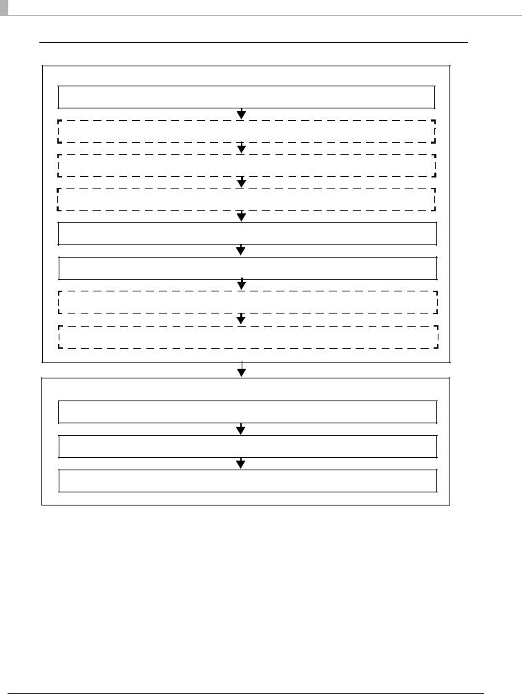
Device Data Notification
Settings for Printer
1.Installing the Product (page 28)
2.Changing the Paper Width (page 32)
3.Adjusting the Paper Roll Near-End Sensor (page 33)
4.Connecting the Peripherals (page 39)
5.Connecting the Product to the Network (page 36)
6.Connecting the AC Adapter (page 44)
7.Attaching the Power Switch Cover (page 45)
8.Setting the Memory Switches/Receipt Enhancement (page 46)
Settings for EPSON TMNet WebConfig
9.Network Setting (page 57)
10.Settings for Connected Devices (page 65)
11.Settings for Device Data Notification (page 74)
26
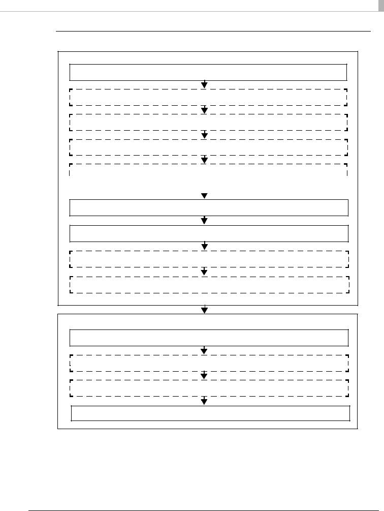
Chapter 2 Setup
Using This Product as a Web Server
Settings for Printer
1.Installing the Product (page 28)
2.Changing the Paper Width (page 32)
3.Adjusting the Paper Roll Near-End Sensor (page 33)
4.Connecting the Peripherals (page 39)
5.Installing the microSD Card (page 35)
|
|
|
|
|
Available when PHP is enabled. |
|
2 |
|||||||||||||||||||||||||||||||||||||||||||||||||||||||
|
|
|
|
|
|
|||||||||||||||||||||||||||||||||||||||||||||||||||||||||
|
|
|
|
|
|
|
||||||||||||||||||||||||||||||||||||||||||||||||||||||||
|
|
|
|
|
|
|
|
|
|
|
|
|
|
|
|
|
|
|
|
|
|
|
|
|
|
|
|
|
|
|
|
|
|
|
|
|
|
|
|
|
|
|
|
|
|
|
|
|
|
|
|
|
|
|
|
|
|
|
|
|
|
|
|
|
|
|
|
|
|
|
|
|
|
|
|
|
|
|
|
|
|
|
|
|
|
|
|
|
|
|
|
|
|
|
|
|
|
|
|
|
|
|
|
|
|
|
|
|
|
|
|
|
|
|
|
|
|
|
|
|
|
|
|
|
|
|
|
|
|
|
|
|
|
|
|
|
|
|
|
|
|
|
|
|
|
|
|
|
|
|
|
|
|
|
|
|
|
|
|
|
|
|
|
|
|
|
|
|
|
|
|
|
|
|
|
|
|
|
|
|
|
|
|
|
|
|
|
|
6.Connecting the Product to the Network (page 36)
7.Connecting the AC Adapter (page 44)
8.Attaching the Power Switch Cover (page 45)
9.Setting the Memory Switches/Receipt Enhancement (page 46)
Settings for EPSON TMNet WebConfig
10.Network Setting (page 57)
11.Enabling HTTPS Communication (page 63)
12.Enabling PHP (page 62)
13.Registering Web Contents (page 67)
27
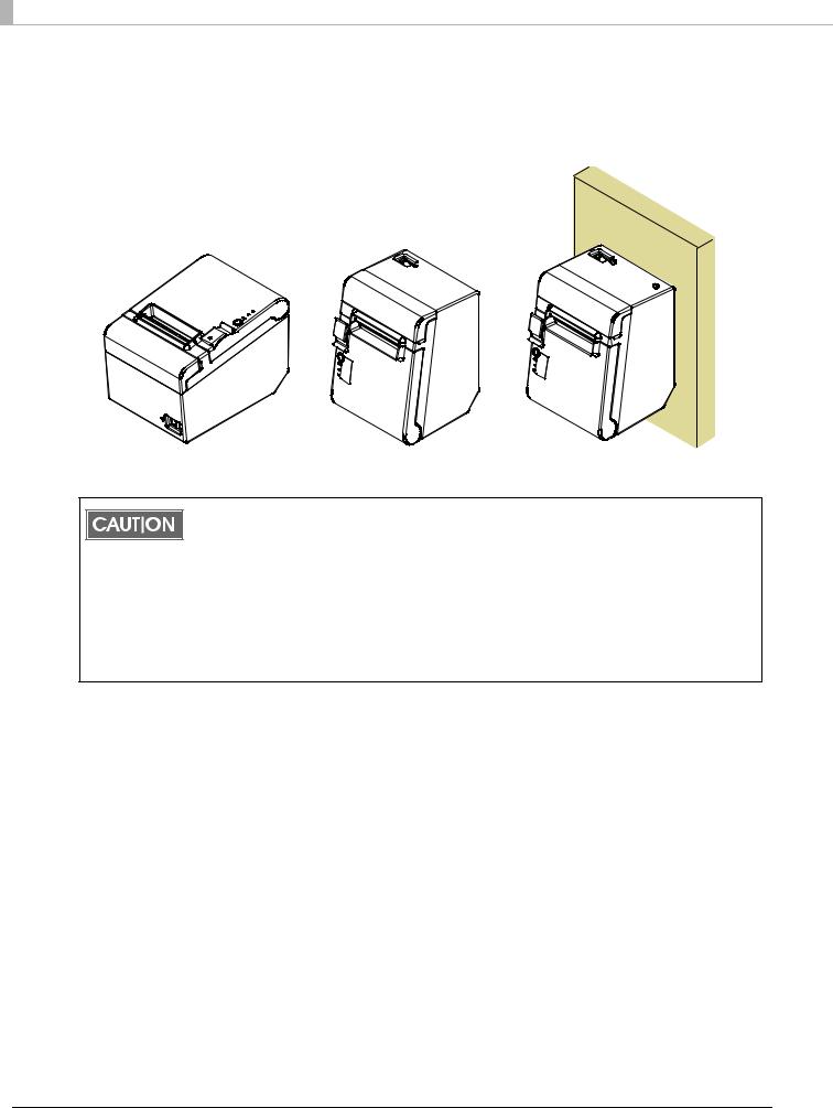
Installing the Product
You can install the printer horizontally on a flat surface (with the paper exit on top) or vertically (with the paper exit at the front). Also, you can hang it on a wall using the included accessories.
Horizontal Installation |
Vertical Installation |
Hanging Installation |
You can use the paper near-end sensor only when you install the printer horizontally.
When you install the printer vertically or hang it on a wall, be sure to disable the setting. Otherwise false detection occur. For information about the paper near-end sensor, see "Adjusting the Paper Roll Near-End Sensor" on page 33.
Take measures to prevent the printer from moving by vibration during paper cutting and when using a drawer. Affixing tape (Model: DF-10) is provided as an option.
Do not place the printer in dusty locations.
Do not knock or strike the printer. This may cause defective print.
Do not catch cables or foreign matter under the printer.
28
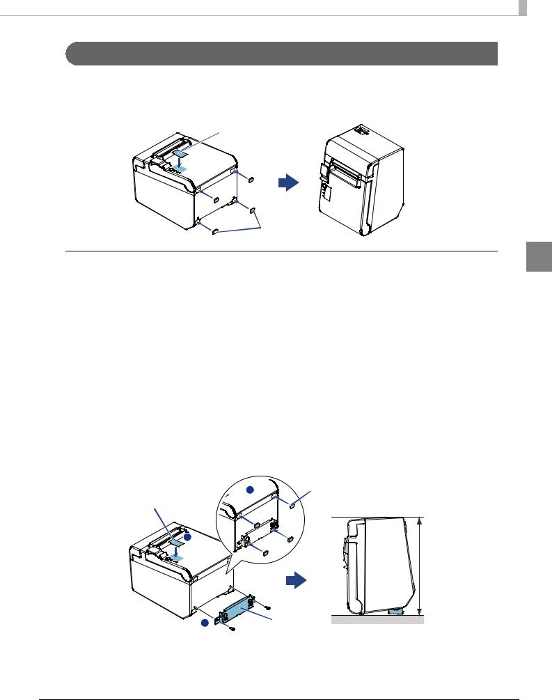
Chapter 2 Setup
Installing the Printer Vertically
When installing the printer vertically, be sure to attach the included control panel label for vertical installation on the roll paper cover, and attach 4 rubber feet in the rectangular indents in the printer case, as shown in the illustration below.
 Control panel label for vertical installation
|
Rubber feet |
Vertical installation |
2 |
You can install the printer so that the roll paper cover is upright to the mounting surface using the included wall hanging bracket.
1 |
Attach the control panel label for vertical installation on the roll paper |
||
|
cover. |
|
|
2 |
Install the wall hanging bracket on the printer, and fix it using 2 included |
||
|
screws. |
|
|
3 |
Attach 2 rubber feet in the rectangular indents in the printer case, and |
||
|
attach 2 rubber feet within the scribed line on the hanging bracket. |
||
4 |
Place the printer with the wall-hanging-bracket-side down. |
||
|
Control panel label |
3 |
Rubber feet |
|
|
|
|
|
for vertical installation |
|
|
|
1 |
|
|
|
|
|
207 mm |
|
|
|
{8.15"} |
|
|
2 |
Wall hanging |
|
|
bracket |
|
|
|
|
|
29
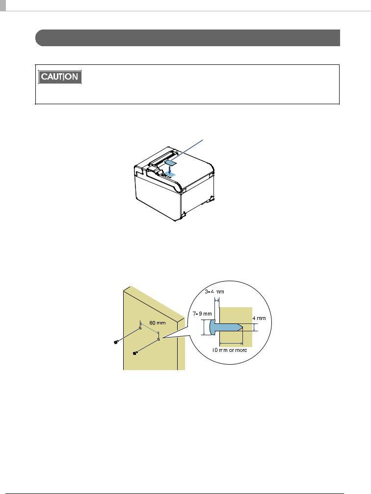
Hanging the Printer on a Wall
To hang the printer on the wall, follow the steps below.
To fix the printer securely, install the wall hanging bracket on a wall made of wood, concrete, or metal. The thickness of the wall should be 10 mm {0.4"} or more.
Be sure to use metallic screws.
The screws on the wall side must have a pull-out strength of 150 N (15.3 kgf) or more.
1Attach the included control panel label for vertical installation on the roll paper cover.
 Control panel label for vertical installation
2 Install 2 screws (screw diameter: 4 mm {0.16"}, head diameter: 7 to 9 mm {0.28 to 0.35"}) in the wall at an interval of 80 mm {3.15"}.
Make sure the length of the screw's body in the wall is 10 mm {0.39"} or more, and the length outside the wall is 3 to 4 mm {0.12 to 0.16"}.
30
 Loading...