


TM-H5000
Return to main menu
TM-H5000/H5000P
Operator’s Manual
Using this online operator’s guide
The words on the left side of this screen are bookmarks for all the
topics in this guide.
Use the scroll bar next to the bookmarks to find any topic you
want. Click a bookmark to instantly jump to its topic. (If you wish,
you can increase the size of the bookmark area by dragging the
dividing bar to the right.)
Use the scroll bar on the right side of this screen to move through
the text.
Use the zoom tools to magnify or reduce the page display.
Click the Find button if you want to search for a particular term.
(However, using the bookmarks is usually quicker.)
Complete online documentation for Acrobat Reader is located in the Help directory for Acrobat Reader.

hybrid printer
TM-H5000/H5000P
Operator’s Manual
MICR Option Included
400613704
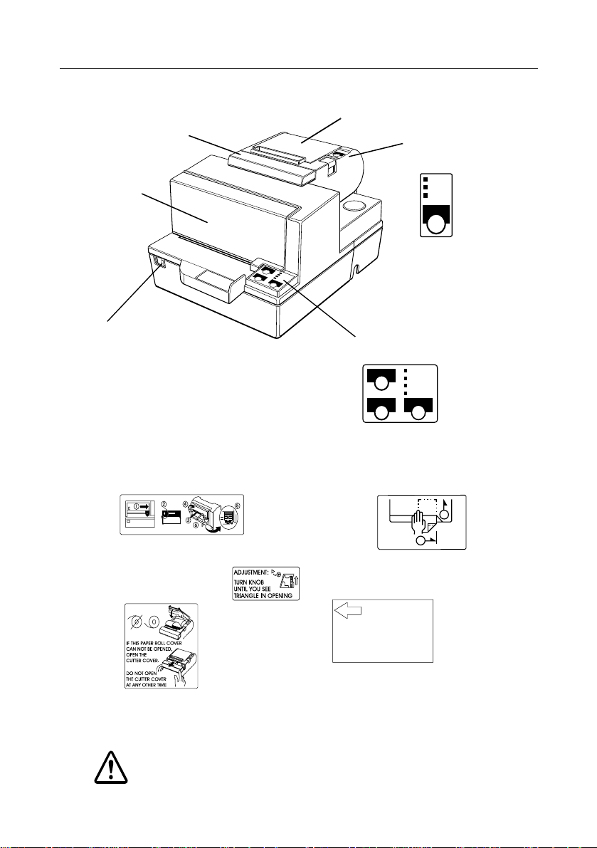
Printer Parts and Labels
Labels
CAUTION:
Caution labels for drawer kick-out and display module
connectors.
ERROR
PAPER
OUT
POWER
FEED
Paper roll
control panel
Paper roll cover
POWER
FORWARD
ERROR
RELEASE
SLIP
REVERSE RELEASE
Slip paper
control panel
Front cover
On/Off switch
Auto-cutter cover
Ribbon installation
front cover
Label affixed on
the document table
Label inside paper
roll cover
Label inside
cutter section
label inside
1
2
Slide open this cutter cover
only whe n paper ro ll cover
cannot be opened.
Instruction label for when
cover won’t open
This label is packed with the printer
Affix the label at the side of the
printer

i
Quick Reference
This Quick Reference will direct you to key ar eas of this Op erator’ s
Manual. For a complete listing of topics, see the Contents.
Printer Parts and Labels inside front cover
Ordering Paper and Ribbons page viii
Where to ord e r paper and ri bbo ns.
Setting Up the Printer page 1-1
How to set up the printer.
Installing and Replacing Paper page 1-10
How to load or change th e roll paper.
Validating and Verifying Checks page 2-5
How to validat e and verify checks using the opti onal Magne tic Ink
Character Recognition (MICR) Reader.
Solving Problems page 3-1
How to correct problems.

ii
All rights reserved. No part of this publication may be reproduced, stored in a
retrieval system, or transmitted in any form or by any means, electronic, mechanical,
photocopying, recording, or otherwise, without the prior written permission of Seiko
Epson Corporation. No patent liability is assumed with respect to the use of the
information contained herein. While every precaution has been taken in the
preparation of this book, Seiko Epson Corporation assumes no responsibility for
errors or omissions. Neither is any liability assumed for damages resulting from the
use of the information contained herein.
Neither Seiko Epson Corporation nor its affiliates shall be liable to the purchaser of
this product or third parties for damages, losses, costs, or expenses incurred by
purchaser or third parties as a result of: accident, misuse, or abuse of this product or
unauthorized modifications, repairs, or alterations to this product, or (excluding the
U.S.) failure to strictly comply with Seiko Epson Corporation’s operating and
maintenance instructions.
Seiko Epson Corporation shall not be liable against any damages or problems arising
from the use of any options or any consumable products other than those designated
as Original Epson Products or Epson Approved Products by Seiko Epson
Corporation.
EPSON and ESC/POS are registered trademarks of Seiko Epson Corporation.
NOTICE: The contents of this manual are subject to change without notice.
Copyright © 1996 by Seiko Epson Corporation, Nagano, Japan.

iii
FCC CLASS A
FCC Compliance Statement
For American Users
This equipment has been tested and found to comply with the limits for a Class A
digital device, pursuant to Part 15 of the FCC Rules. These limits are designed to
provide reasonable protection against harmful interf erence when the equipment is
operated in a commercial environment.
This equipment generates, uses, and can radiate radio frequency energy and, if not
installed and used in accordance with the instructio n manua l , may cause har mful
interference to radio communications. Operation of this equipment in a residential
area is likely to cause harmful interference, in which case the user will be requ ired to
correct the interference at his own expense.
WARNING
The connection of a non-shielded pri nter interface c able to this p rinter will invalidate
the FCC Verification of this device and may cause interference levels which exceed
the limits established by the FCC for this equipment.
You are cautioned that changes or modifications not expressly approved by the
party responsible for compliance could void your authority to operate the
equipment.
FOR CANADIAN USERS
This Class A digital apparatus meets all requirements of the Canadian Interference-
Causing Equipment Regulations.
Cet appareil numérique de la classe A respecte toutes les exigenves du Règlement
sur le matériel brouileur du Canada.
GEREÄUSCHPEGEL
Gemäß der Dritten Verordnung zum Gerätesicherheitsgesetz
(Maschinenlärminformations- Verordnung-3. GSGV) ist der arbeitsplatzbezogene
Geräusch-Emissionswert kleiner als 70 dB(A) (ba sierend auf ISO 7779).

iv
Product Name : Printer
Type Name: M128A
These printers conform to the following Directives and Norms
Directive 89/336/EEC
EN 55022 (1986 and 1994) Class B
EN 50082-1 (1992)
IEC 801-2 (1991)
IEC 801-3 (1984)
IEC 801-4 (1991)
Directive 90/384/EEC
EN4550 1: (1 99 2)
DECLARATION OF CONFORMIT Y

v
EMI and Safety Standards Applied
The following stan dards are applied on ly to the printers t hat ar e so
labeled. (EMC is tested using the EPSON PS-170 power supply)
Europe: CE marking
EN55022
EN50082-1
EN45501
Safety Standard: TÜV
North America: EMI: FCC Class A
Safety standards: UL 1950-2TH-D3
C-UL
Japan: EMI: VCCI Class 1
vi
About This Manual
Setting Up and Using
❏ Chapter 1 contains information on unpacking the printer, setting it up, setting
the DIP switches, and adjusting the paper near end sensor.
❏ Chapter 2 contains information on using the printer.
❏ Chapter 3 contains troubleshooti ng i nformation.
Reference
❏ Chapter 4 contains specificatio ns
❏ Appendix A tells how to change the DIP switch and paper near end settings,
and Appendix B lists the EPSON Sales Subsidiaries and their addresses.
Warnings, Cautions, and Notes
WARNING:
Warnings must be followed carefully to avoid serious bodily
injury.
CAUTION:
Cautions must be observed to avoid minor injury to yourself or
damage to your equipment.
Note:
Notes have important information and useful tips on the operation of your
printer.

Introductionvii
Introduction
Features
The TM-H5000 and TM-H5000P are high-quality POS printers that can print on slip
and receipt paper (paper roll). The printers have the following features:
Slip Section
❏ Wide slip paper capability (maximum characters per line: 88 with 7 × 9 font).
❏ Copy printing is possible.
❏ High throughput using bidirectional, minimum distance printing.
❏ Optional Magnetic Ink Character Recognition (MICR) reader that enables the
printer to perform consecutive reading and processing of MICR characters and
printing endorsements.
Receipt Section
❏ High speed printing with collective printing.
❏ The standard auto-cutter provides easy user operation.
❏ Ladder bar code printing is possible by using a bar code command.
❏ New paper handling enables easy paper roll loading.
Both Receipt and Slip
❏ EPSON customer display series connection (DM-D102-012/DM-D203-012 ).
❏ Selectable receive buffe r size (45 byte s or 4K byte s ).
❏ Command protocol based on the ECS/POS
®
standard.
❏ Automatic Status Back (ASB) function that automatically transmits changes in
the printer status.

viii Introduction
Options and Accessories
❏ Magnetic Ink Character Recogniti on (MICR) reader (factory installed option)
❏ Direct con nection display modu l e s , DM-D102-012 and DM-D2 03-012
❏ EPSON po we r su pp ly un i t, PS -170
❏ EPSON ribbon cassette, ERC-31(P)
❏ Front extens ion table (WT-5000)
Ordering Paper and Supplies
Thermal paper can be ordered from the supplier in your area.
Specified Thermal Paper: NTP080-80
In Japan: Nakagawa S e isa kujo
2-5-21 Nishiki-Cho Warabi-Shi
Saitama-Ken 335 Japan
Tel: (048) 444-8211
Fax: (048) 443-6652
In U.S.A.: Nakagawa Mfg (USA) Inc.
2305 Lincoln Avenue
Hayward, CA 94545 USA
Tel: (510) 782-0197
Fax: (510) 782-7124
In Europe: Nakagawa Mfg (Europe) GmbH.
Krützpoort 16, 47804
Krefeld, Germany
Tel: 02151-711051
Fax: 02151-713293

Introduction ix
In Southeast Asia: N.A.K. Mfg (Malaysia) SDN BHD
Lot 19-11, Bersatu Industrial Complexs,
Jalan Satu, Kaw Per. Cheras Jaya,.
Balakong Industrial Area, 43200 Cheras.
Sela ngo r Dar ul Ehsan , Malaysia
Tel: 03-9047896, 9047900, 9047691
Fax: 03-9047889
Other Qualified Suppliers for Thermal Paper
The following suppliers sell thermal paper that may be used if
desired. Contact each company for information.
Original paper: TF50KS-E
Nippon Paper Industry Co., Ltd.
1-12-1, Yuraku-Cho, Chiyoda-Ku
Tokyo 100 Japan
Tel: 03-3218-8000
Fax: 03-3216-1375
Original paper: PD 160R
New Oji Paper Mfg. Co., Ltd.
7-5 Ginza 4-Chome Chuo-Ku
Tokyo 104 Japan
Tel: 03-3563-4800
Fax: 03-3563-1136
Original paper: AF50KS-E
Jujo Thermal Oy (Finland)
P.O. Box 92 FIN27501 Kauttua Finland
Tel: 38-3932900
Fax: 38-3932419

x Introduction
Original paper: F380
Kanzaki Specialty Papers, Inc.
Cummings Street
Ware, MA 01082 U.S.A.
Tel: (413)967-6204
Fax: (413) 734-5101
Ordering Ribbon Cassettes
The TM-H5000/H5000P uses a long-lasting ribbon cassette in the
slip secti on. To ord e r ribbon cass ettes, contact your dealer or yo ur
local affiliate. See Appendix B for a list of EPSON subsidiaries with
their addresses and telephone numbers.

xi
Contents
Quick Reference . . . . . . . . . . . . . . . . . . . . . . . . . . . . . . . . . . . . . . . . . . . . . . . . . . . . . . . i
Introduction . . . . . . . . . . . . . . . . . . . . . . . . . . . . . . . . . . . . . . . . . . . . . . . . . . . . . . . . . . vii
Chapter 1
Setting Up the Printer
Unpacking . . . . . . . . . . . . . . . . . . . . . . . . . . . . . . . . . . . . . . . . . . . . . . . . . . . . . . . . . . . . 1-1
Removing the protective material . . . . . . . . . . . . . . . . . . . . . . . . . . . . . . . . . . . . 1-2
Connecting the Cables and Grounding the Printer . . . . . . . . . . . . . . . . . . . . . . . . . . 1-3
Connecting the Drawer . . . . . . . . . . . . . . . . . . . . . . . . . . . . . . . . . . . . . . . . . . . . . 1-5
Connecting the Display Module . . . . . . . . . . . . . . . . . . . . . . . . . . . . . . . . . . . . . 1-7
Grounding the Printer . . . . . . . . . . . . . . . . . . . . . . . . . . . . . . . . . . . . . . . . . . . . . . 1-7
Connecting the Power Supply . . . . . . . . . . . . . . . . . . . . . . . . . . . . . . . . . . . . . . . 1-8
Installing or Replacing the Paper Roll . . . . . . . . . . . . . . . . . . . . . . . . . . . . . . . . . . . . . 1-10
Installing the Ribbon Cassette . . . . . . . . . . . . . . . . . . . . . . . . . . . . . . . . . . . . . . . . . . . 1-13
Using the Power Switch Cover . . . . . . . . . . . . . . . . . . . . . . . . . . . . . . . . . . . . . . . . . . . 1-15
Self Test . . . . . . . . . . . . . . . . . . . . . . . . . . . . . . . . . . . . . . . . . . . . . . . . . . . . . . . . . . . . . . 1-15
Running the self test with a paper roll . . . . . . . . . . . . . . . . . . . . . . . . . . . . . . . . 1-15
Running the self test with slip paper . . . . . . . . . . . . . . . . . . . . . . . . . . . . . . . . . . 1-16
Adjustments and Settings . . . . . . . . . . . . . . . . . . . . . . . . . . . . . . . . . . . . . . . . . . . . . . . 1-17
Chapter 2
Using the Printer
Operating the Control Panels . . . . . . . . . . . . . . . . . . . . . . . . . . . . . . . . . . . . . . . . . . . . 2-1
Paper Roll Control Panel . . . . . . . . . . . . . . . . . . . . . . . . . . . . . . . . . . . . . . . . . . . . 2-1
Slip Control Panel . . . . . . . . . . . . . . . . . . . . . . . . . . . . . . . . . . . . . . . . . . . . . . . . . . 2-1
Indicator lights . . . . . . . . . . . . . . . . . . . . . . . . . . . . . . . . . . . . . . . . . . . . . . . . . . . . 2-2
Slip Paper Handling . . . . . . . . . . . . . . . . . . . . . . . . . . . . . . . . . . . . . . . . . . . . . . . . . . . . 2-3
Using the MICR Reader (Option) . . . . . . . . . . . . . . . . . . . . . . . . . . . . . . . . . . . . . . . . 2-5
Reading MICR characters on personal checks . . . . . . . . . . . . . . . . . . . . . . . . . . 2-5
Chapter 3
Troubleshooting
Troubleshooting . . . . . . . . . . . . . . . . . . . . . . . . . . . . . . . . . . . . . . . . . . . . . . . . . . . . . . . 3-1
General problems . . . . . . . . . . . . . . . . . . . . . . . . . . . . . . . . . . . . . . . . . . . . . . . . . . 3-1
Printing problems . . . . . . . . . . . . . . . . . . . . . . . . . . . . . . . . . . . . . . . . . . . . . . . . . . 3-1
Cleaning the paper roll print head . . . . . . . . . . . . . . . . . . . . . . . . . . . . . . . . . . . 3-3
Paper handling problems . . . . . . . . . . . . . . . . . . . . . . . . . . . . . . . . . . . . . . . . . . . 3-4
Auto cutter problems . . . . . . . . . . . . . . . . . . . . . . . . . . . . . . . . . . . . . . . . . . . . . . . 3-6
Cleaning the Optional MICR Mechanism . . . . . . . . . . . . . . . . . . . . . . . . . . . . . . . . . 3-7
MICA cleaning method (Recommended) . . . . . . . . . . . . . . . . . . . . . . . . . . . . . 3-7
The cleaning procedure . . . . . . . . . . . . . . . . . . . . . . . . . . . . . . . . . . . . . . . . . . . . . 3-7
Explanatin of a cleaning sheet . . . . . . . . . . . . . . . . . . . . . . . . . . . . . . . . . . . . . . . 3-9
Hexadecimal Dump . . . . . . . . . . . . . . . . . . . . . . . . . . . . . . . . . . . . . . . . . . . . . . . . . . . . 3-10

xii
Chapter 4 Reference Information
Printing Specifications . . . . . . . . . . . . . . . . . . . . . . . . . . . . . . . . . . . . . . . . . . . . . . . . . . 4-1
Slip Paper . . . . . . . . . . . . . . . . . . . . . . . . . . . . . . . . . . . . . . . . . . . . . . . . . . . . . . . . . 4-1
Receipt Paper . . . . . . . . . . . . . . . . . . . . . . . . . . . . . . . . . . . . . . . . . . . . . . . . . . . . . 4-2
Ribbon Specifications . . . . . . . . . . . . . . . . . . . . . . . . . . . . . . . . . . . . . . . . . . . . . . . . . . . 4-4
MICR Reader (Option) . . . . . . . . . . . . . . . . . . . . . . . . . . . . . . . . . . . . . . . . . . . . . . . . . 4-4
Paper Specifications . . . . . . . . . . . . . . . . . . . . . . . . . . . . . . . . . . . . . . . . . . . . . . . . . . . . 4-5
Electrical Characteristics . . . . . . . . . . . . . . . . . . . . . . . . . . . . . . . . . . . . . . . . . . . . . . . . 4-10
Reliability . . . . . . . . . . . . . . . . . . . . . . . . . . . . . . . . . . . . . . . . . . . . . . . . . . . . . . . . . . . . . 4-10
Environmental Conditions . . . . . . . . . . . . . . . . . . . . . . . . . . . . . . . . . . . . . . . . . . . . . . 4-12
Chapter 5 Commands
Command Notation . . . . . . . . . . . . . . . . . . . . . . . . . . . . . . . . . . . . . . . . . . . . . . . . . . . . 5-1
Explanation of Terms . . . . . . . . . . . . . . . . . . . . . . . . . . . . . . . . . . . . . . . . . . . . . . . . . . . 5-1
Control Commands . . . . . . . . . . . . . . . . . . . . . . . . . . . . . . . . . . . . . . . . . . . . . . . . . . . . 5-1
MICR Control Commands (only for printers with MICR) . . . . . . . . . . . . . . . . . . . . 5-28
Appendix A Dip Switch and Paper Near End Settings
Setting the DIP Switches . . . . . . . . . . . . . . . . . . . . . . . . . . . . . . . . . . . . . . . . . . . . . . . . A-1
DIP switch functions . . . . . . . . . . . . . . . . . . . . . . . . . . . . . . . . . . . . . . . . . . . . . . . A-1
Changing the DIP switch settings . . . . . . . . . . . . . . . . . . . . . . . . . . . . . . . . . . . . A-6
Adjusting the Paper Near End Sensor . . . . . . . . . . . . . . . . . . . . . . . . . . . . . . . . . . . . A-7
Appendix B EPSON Sales Subsidiaries
Setting Up the Printer 1-1
Chapter 1
Setting Up the Printer
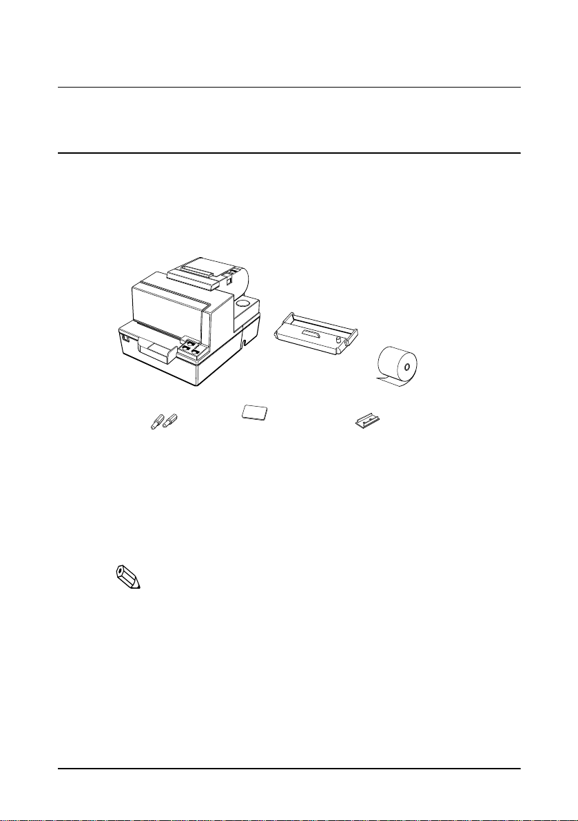
Unpacking
Your printer box should include these items. If any items are
damaged or missing, please contact your dealer for assistance.
See the note on page 1-4 for information about the hexagonal lock screws.
Note:
When you lift the printer, be sure to hold the bottom of the
printer to prevent damage.
Instruction label for
when paper roll cover
cannot be opened
Hexagonal
lock screws
These screws are used
only for the serial interface
Paper roll
Switch
cover
Ribbon
1-2 Setting Up the Printer
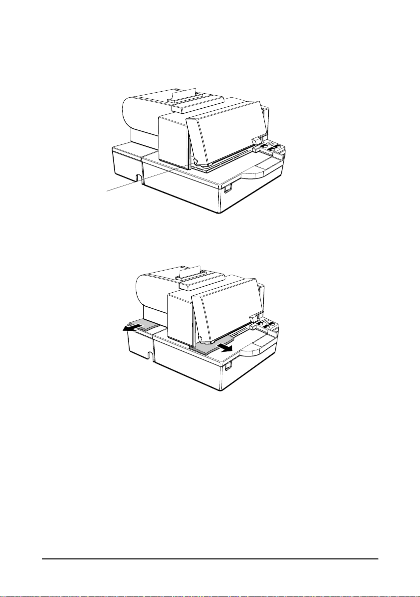
Removing the protective material
1. Open the printer by pulling up on the tab on the front cover.
2. Remove the two dampers from the printer as shown below.
3. Store th e da mpers with the othe r packing materials and use
them when transporting your printer.
Tab

Setting Up the Printer 1-3
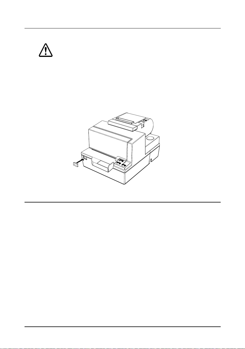
Connecting the Cables and Grounding the Printer
You can connect up to five cables to the printer. They all connect to
the conn ec tor panel on the botto m of the pri nter, whic h is shown
below:
Note:
There are caution labels beside the drawer kick-out connector
and the display module connector.
Depending on the interface installed, the interface connector on
your printer may look different from the one illustrated.
Before connecting any of the cables, make sure that both the printer
and the computer are turned off.
Connecting the computer
You need an appropriate interface cable.
1. Plug the cable connector securely into the printer’s interface
connector.
Grounding screw
Power supply
Drawer kick-out
Display module
Interface
1-4 Setting Up the Printer
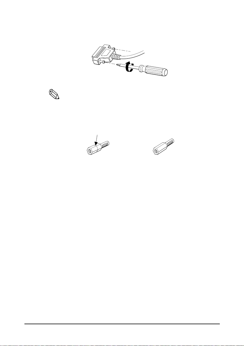
2. Tighten the screws on both sides of the cable connector.
Note:
Your printer has inch-type hexagonal lock screws installed. If
your interface cable requires millimeter-type screws, replace the
inch-type screws with the enclosed millimeter-type screws using
a hex screwdriver (5 mm).
3. Attach the other end of the cable to the compu te r.
Inch screw
Millimeter screw
Setting Up the Printer 1-5
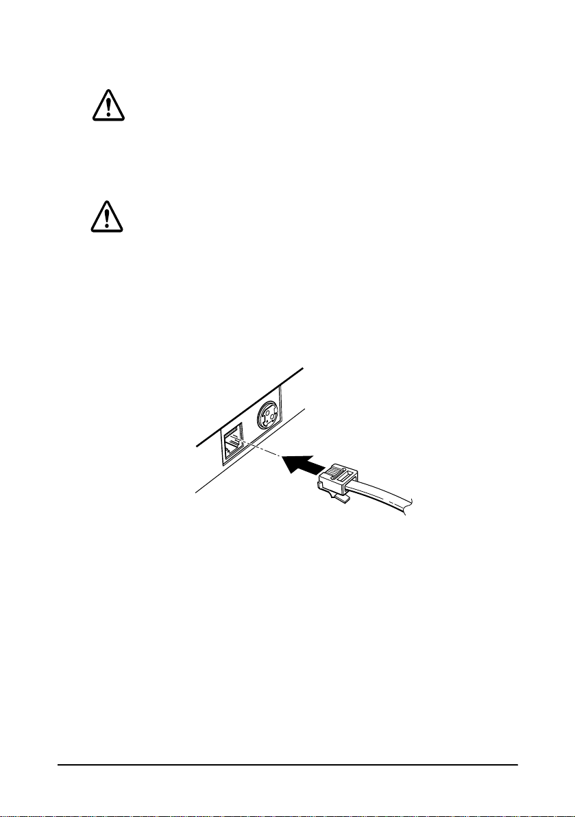
Connecting the Drawer
WARNING:
Use a drawer that matches the printer specification. Using an
improper drawer may damage the drawer as well as the
printer.
CAUTION:
Do not connect a telephone line to the drawer kick-out
connector; otherwise the printer and the telephone line may
be damaged.
Plug the drawer cable into the drawer kick-out connector on the
bottom of th e printer nex t to the power supply connector.
1-6 Setting Up the Printer
Anschließen der Lade
WARNUNG:
Eine für den Drucker geeignete Lade verwenden. Bei
Verwendung einer falschen Lade kann diese oder der
Drucker beschädigt werden.
ACHTUNG:
Kein Telefonkabel an die Schnappsteckerbuchse
anschließen, da sonst der Drucker und die Telefonkabel
besch
ä
digt werden können.
Das Kabel der Lade an die Schnappsteckerbuchse unten am
Drucker ne be n dem Netßza nschluß
anschlie
ß
en
.
Setting Up the Printer 1-7
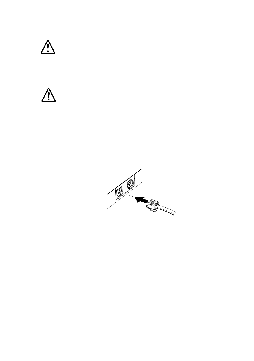
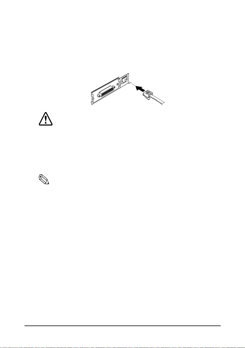
Connecting the Display Module
Plug the c able connec tor (provide d with th e di rect conne ction
display module) securely into the printer’s display module
connector until it clicks.
CAUTION:
Be sure not to connect this cable to the drawer kick-out
connector, which is to the left of the power supply
connector. Do not connect a telephone line to the
display connector. If you do, the printer and the
telephone line may be damaged.
Notes:
The display module can be used only for the serial interface.
To remove the cable, squeeze the connector and pull it out.
Grounding the Printer
You need a ground wire to ground your printer. Make sure that the
wire is AWG 18 or equivalent.
1. Make sure that the printer is turned off.
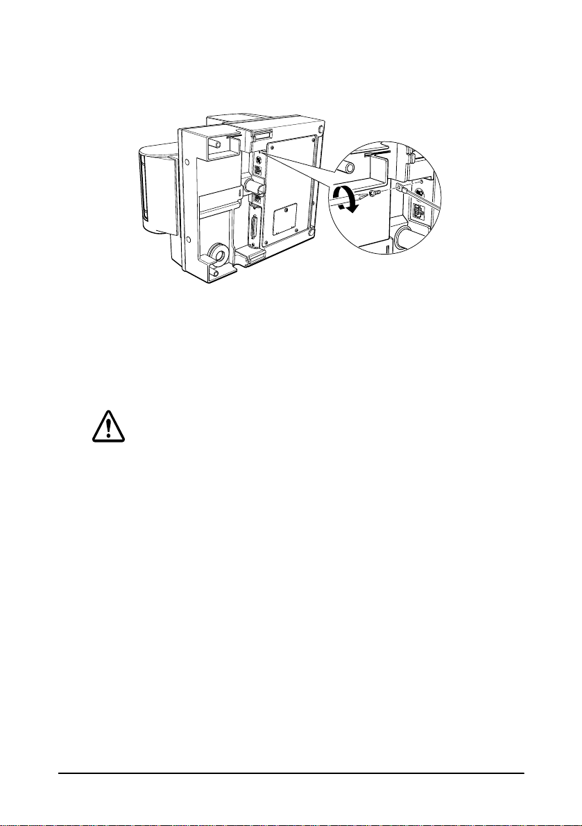
1-8 Setting Up the Printer
2. Connect the ground wire to the printer using the FG scre w o n
the bottom of the printer, as shown.
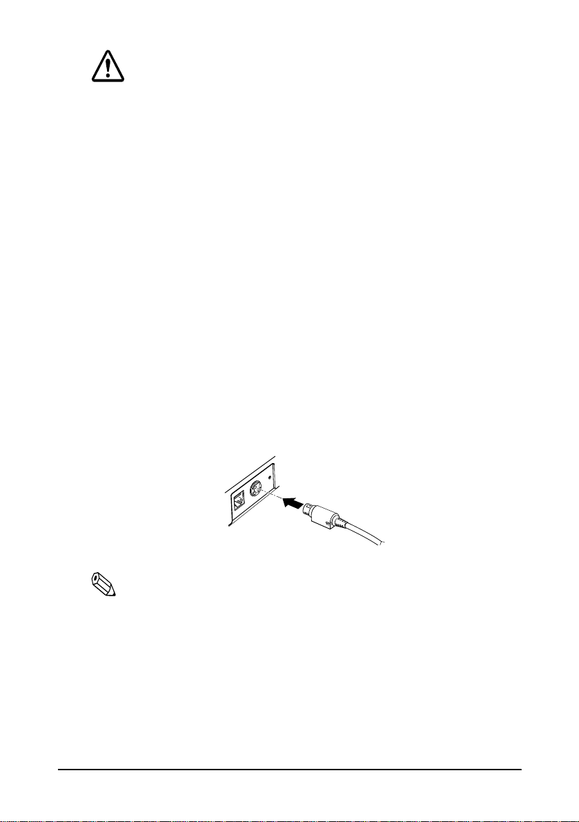
Connecting the Power Supply
Use the optional EPSON PS-170 or equivalent power supply for
your printer.
WARNING:
Make sure that you use the EPSON PS-170 power supply or
equivalent. Using an incorrect power supply may cause fire or
electrical shock.
Setting Up the Printer 1-9
CAUTIONS:
When connecting or disconnecting the power supply from
the printer, make sure that the power supply is not plugged
into an electrical outlet. Otherwise you may damage the
power supply or the printer.
If the power supply’s rated voltage and your outlet’s voltage
do not match, contact your dealer for assistance. Do not
plug in the power cord. Otherwise you may damage the
power supply or the printer.
1. Make sure that the printer’s power switch is turned off, and the
power supply’s po wer cord is unplugged from the electrical
outlet.
2. Check th e la be l on the power supply to make sure that the
voltage required by the power supply matches that of your
electrical outlet.
3. Plug in the power supply’s ca ble as shown below. N otice that
the flat side of the plug faces down.
Note:
To remove the DC cable connector, make sure that the power
supply’s power cord is unplugged; then grasp the connector at the
arrow and pull it straight out.
1-10 Setting Up the Printer
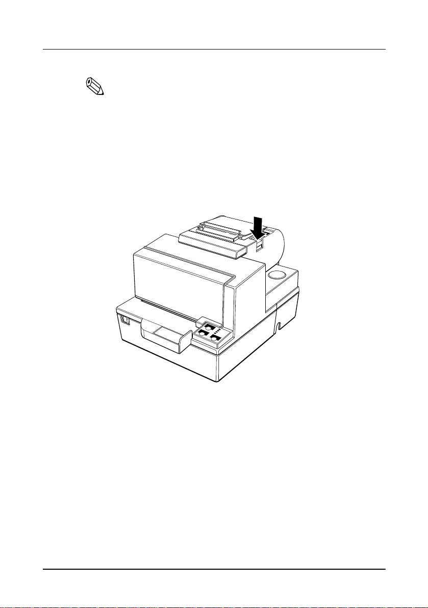
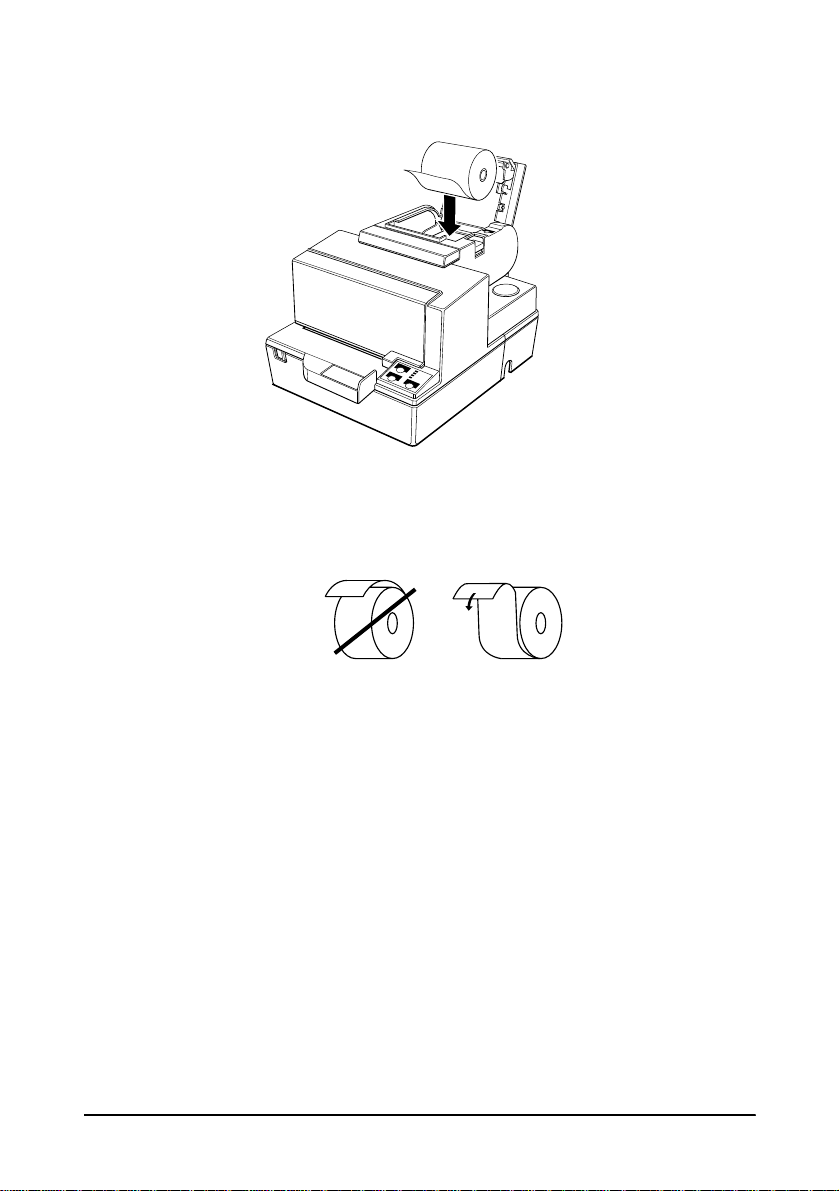
Installing or Replacing the Paper Roll
Note:
Be sure to use paper rolls that meet the specifications. Do not
use paper rolls that have the paper glued to the core because the
printer cannot detect the paper end correctly.
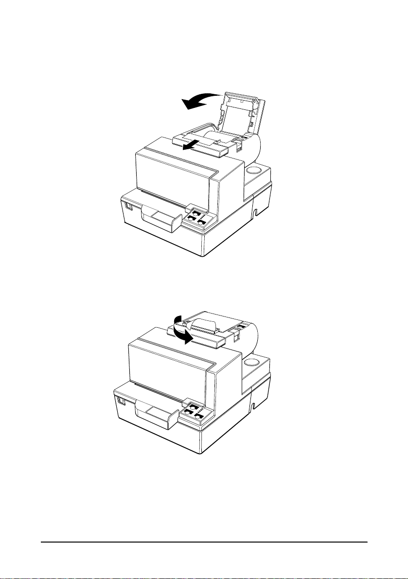
1. Make sure that the printer is not receiving data; otherwise, data
may be lost.
2. Open the paper roll cover by pressing the cover-open button. If
the cover-open button will not open the cover, see page 3-4 in
Troubleshooting.
3. Remove the used paper roll core i f there is one.
Setting Up the Printer 1-11
4. Insert the paper rol l as shown .
5. Be sure to note the correct direction that the paper comes off the
roll.
1-12 Setting Up the Printer
6. Pull out a small amount of paper, as shown. Then close the
cover.
7. Tear off the paper as shown.
Setting Up the Printer 1-13
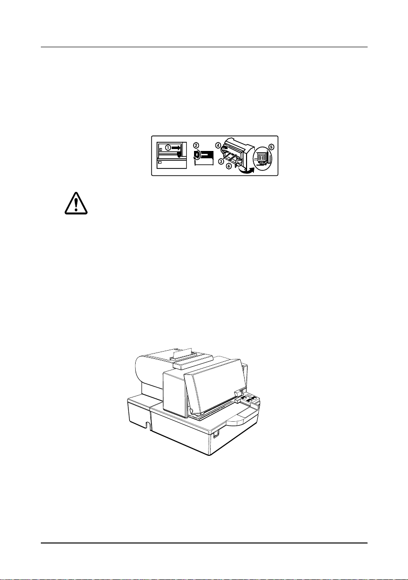
Installing the Ribbon Cassette
Use the E PSON ERC-31(P) ribbon cassette for your printer.
Note the label inside this section that can assist you in replacing the
ribbon.
CAUTION:
Never turn the ribbon knob in the opposite direction of
the arrow marked on the cassette; otherwise the ribbon
cassette may be damaged.
1. Be sure the printer is not receiving data when you replace a
ribbon cass ette; otherwi se data ma y be lost.
2. Turn on the printer and open the front cover by pulling up on
the tab on the left side of the co ver.
3. Make sure that the print head is on the right side.
1-14 Setting Up the Printer
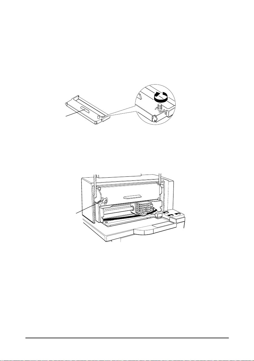
4. If you are replacing a used ribbon, grasp the end of the tab and
remove it from the printer. See the illustration in step 5 for the
location of the tab.
5. Turn the ribbon kn ob two or three times in the direction of the
arrow to ta ke up any slac k i n the ribbon.
6. Insert the ribbon ca ssette in th e printer an d rotate the cassette's
knob two or three more times. This is necessary to place the
ribbon in the correct posi tion.
Make sure that the ri bbon is inst alled below the print h e ad
without wrinkles or creases. (See ➄ on the label for an
illustration of where the ribbon should go.)
If the ribbon is not installed cor rectly, remove the cassette and
repeat steps 5 and 6 above.
Tab
Knob
Setting Up the Printer 1-15
Using the Power Switch Cover
WARNING:
If an accident occurs when the power switch cover is
attached, unplug the power supply cord from the outlet
immediately. Continued usage may lead to fire or shock.
You can use the enclosed power switch cover to make sure that the
power switch is not accidentally pressed. If you want to use this
cover, install it as shown in the illustration below.
Self Test
The self test lets you know if your printer is operating properly. I t
checks the control circuits, printer mechanisms, print quality, ROM
version, and DIP switch settings. (It also checks the MICR reader
circuits if the printer is equippe d with the o p ti onal MICR reader.)
This test is independe nt o f any other e quipment or software.
You can run the self test with either paper roll or slip paper .
Running the self test with a paper roll
1. Make sure the printe r is turned off and the pri nter cove rs are
closed properly.
 Loading...