


 Loading...
TM-U200 Series (Type A)
Operator’s Manual
Using this online operator’s guide
The words on the left side of this screen are bookmarks for all the topics in this guide.
Use the scroll bar next to the bookmarks to find any topic you want. Click a bookmark to instantly jump to its topic. (If you wish, you can increase the size of the bookmark area by dragging the dividing bar to the right.)
Use the scroll bar on the right side of this screen to move through the text.
Use the zoom tools to magnify or reduce the page display.
Click the Find button if you want to search for a particular term. (However, using the bookmarks is usually quicker.)
Complete online documentation for Acrobat Reader is located in the Help directory for Acrobat Reader.
Return to main menu

TM-U200 Series
(Type A)
Operator’s Manual
400898901
Note:
Everything in this manual applies to the TM-U210 printer.
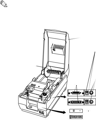
Printer parts and Labels
 Printer cover
Drawer kick-out connectors
Journal take-up  spool
spool
Interface |
Power connector |
|
|
Connector |
|
Model with Serial
Interface
Model with
Parallel Interface


 DIP switches
Power switch
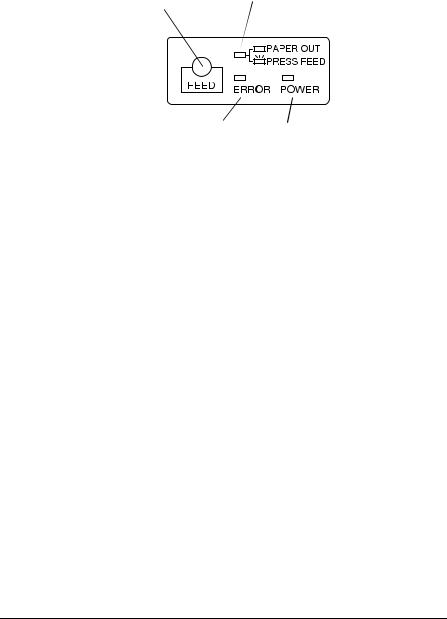
Control panel
PAPER FEED |
PAPER OUT light |
|
button |
||
|
ERROR light |
POWER light |
Caution Labels
 CAUTION:
Head cover and printer head are hot.
 CAUTION:
Caution label for drawer kick-out.
Instruction Label

All rights reserved. No part of this publication may be reproduced, stored in a retrieval system, or transmitted in any form or by any means, mechanical, photocopying, recording, or otherwise, without the prior written permission of Seiko Epson Corporation. No patent liability is assumed with respect to the use of the information contained herein. While every precaution has been taken in the preparation of this book, Seiko Epson Corporation assumes no responsibility for errors or omissions. Neither is any liability assumed for damages resulting from the use of the information contained herein.
Neither Seiko Epson Corporation nor its affiliates shall be liable to the purchaser of this product or third parties for damages, losses, costs, or expenses incurred by purchaser or third parties as a result of: accident, misuse, or abuse of this product or unauthorized modifications, repairs, or alterations to this product, or (excluding the U.S.) failure to strictly comply with Seiko Epson Corporation’s operating and maintenance instructions.
Seiko Epson Corporation shall not be liable against any damages or problems arising from the use of any options or any consumable products other than those designated as Original Epson Products or Epson Approved Products by Seiko Epson Corporation.
EPSON is a registered trademark of Seiko Epson Corporation. ESC/POS is a registered trademark of Seiko Epson Corporation.
NOTICE: The contents of this manual are subject to change without notice.
Copyright © 1998 by Seiko Epson Corporation, Nagano, Japan.
i

FCC CLASS A
FCC Compliance Statement
For American Users
This equipment has been tested and found to comply with the limits for a Class A digital device, pursuant to Part 15 of the FCC Rules. These limits are designed to provide reasonable protection against harmful interference when the equipment is operated in a commercial environment.
This equipment generates, uses, and can radiate radio frequency energy and, if not installed and used in accordance with the instruction manual, may cause harmful interference to radio communications. Operation of this equipment in a residential area is likely to cause harmful interference, in which case the user will be required to correct the interference at his own expense.
WARNING
The connection of a non-shielded printer interface cable to this printer will invalidate the FCC Verification of this device and may cause interference levels which exceed the limits established by the FCC for this equipment.
You are cautioned that changes or modifications not expressly approved by the party responsible for compliance could void your authority to operate the equipment.
FOR CANADIAN USERS
This Class [*] digital apparatus complies with Canadian ICES-003.
Cet appareil numérique de la classe [*] est conforme à la norme NMB-003 du Canada.
GERÄUSCHPEGEL
Gemäß der Dritten Verordnung zum Gerätesicherheitsgesetz (Maschinenlärminformations- Verordnung-3. GSGV) ist der arbeitsplatzbezogene Geräusch-Emissionswert kleiner als 70 dB(A) (basierend auf ISO 7779).
ii

DECLARATION OF CONFORMITY
Product Name: Printer
Model Name: M119A
This printer conforms to the following Directives and Norms:
Directive 89/336/EEC
EN 55022 (1987 and 1994 2nd/1995) Class B
EN 50082-1 (1992)
IEC 801-2 (1991)
IEC 801-3 (1984)
IEC 801-4 (1988)
Directive 90/384/EEC
EN45501: (1992)
iii

Introduction
Features
The TM-U200 Series Type A printer is one-station printer for ECR and POS use that can print the results of weighing or measuring.
TM-U200 Series (Type A) has the following 2 types.
∙Two-color with a serial interface
∙Two-color with a parallel interface
The main features of the TM-U200 Series Type A printer are the following:
High-speed printing through logic-seeking control
Excellent reliability and long life due to use of two stepping motors, one for moving the carriage and one for paper feeding
Flexible paper feed setting permits printing in accordance with any user-defined format
Command protocol based on ESC/POS ,® a widely used standard
Built-in drawer kick-out interface provides capability to drive two drawers
Selectable character fonts (7 x 9, 9 x 9)
Semi-automatic paper loading capability
AC adapter provides compact power supply
Compact and light in weight
Automatic Status Back (ASB) function to automatically send printer status changes
Auto cutter is installed
Journal take-up spool is installed
Bidirectional parallel interface in accordance with the IEEE 1284 Nibble/Byte Modes
Two-color printing (black and red)
iv

About This Manual
Setting Up and Using
Chapter 1 contains information on unpacking the printer, setting it up, running the self test, and setting the DIP switches.
Chapter 2 contains information on using the printer.
Chapter 3 contains troubleshooting information.
Reference
Chapter 4 contains specifications.
Notes, Cautions, and Warnings
Note:
Notes have important information and useful tips on the operation of your printer.
 CAUTION:
Cautions must be observed to avoid minor injury to yourself or damage to your equipment.
 WARNING:
Warnings must be followed carefully to avoid serious bodily injury.
v

Contents
Chapter 1 Setting Up the Printer
Unpacking . . . . . . . . . . . . . . . . . . . . . . . . . . . . . . . . . . . . . . . . . . . . . . . . . . . . . . . . . . . . 1-1 Selecting the Place . . . . . . . . . . . . . . . . . . . . . . . . . . . . . . . . . . . . . . . . . . . . . . . . . . . . . 1-1 Attaching the Paper Roll Near-End Detector (Option) . . . . . . . . . . . . . . . . . . . . . . . 1-2 Connecting the Printer to the Computer . . . . . . . . . . . . . . . . . . . . . . . . . . . . . . . . . . 1-5 Serial Interface . . . . . . . . . . . . . . . . . . . . . . . . . . . . . . . . . . . . . . . . . . . . . . . . . . . . 1-5 Parallel Interface . . . . . . . . . . . . . . . . . . . . . . . . . . . . . . . . . . . . . . . . . . . . . . . . . . . 1-6 Connecting the Printer to the Drawer . . . . . . . . . . . . . . . . . . . . . . . . . . . . . . . . . . . . . 1-6 Grounding the Printer . . . . . . . . . . . . . . . . . . . . . . . . . . . . . . . . . . . . . . . . . . . . . . . . . . 1-9 Connecting the Power Supply . . . . . . . . . . . . . . . . . . . . . . . . . . . . . . . . . . . . . . . . . . . 1-10 Installing the Ribbon Cassette . . . . . . . . . . . . . . . . . . . . . . . . . . . . . . . . . . . . . . . . . . . 1-12 Installing the Paper Roll . . . . . . . . . . . . . . . . . . . . . . . . . . . . . . . . . . . . . . . . . . . . . . . . 1-15 Running the Self Test . . . . . . . . . . . . . . . . . . . . . . . . . . . . . . . . . . . . . . . . . . . . . . . . . . . 1-20 Setting the DIP Switches . . . . . . . . . . . . . . . . . . . . . . . . . . . . . . . . . . . . . . . . . . . . . . . . 1-21 Using the Power Switch Cover . . . . . . . . . . . . . . . . . . . . . . . . . . . . . . . . . . . . . . . . . . . 1-25 Affixing the Fastening Tape (Option) . . . . . . . . . . . . . . . . . . . . . . . . . . . . . . . . . . . . . 1-26
Chapter 2 Using the Printer
Operating the Control Panel . . . . . . . . . . . . . . . . . . . . . . . . . . . . . . . . . . . . . . . . . . . . . 2-1 Switch . . . . . . . . . . . . . . . . . . . . . . . . . . . . . . . . . . . . . . . . . . . . . . . . . . . . . . . . . . . . 2-1 Button . . . . . . . . . . . . . . . . . . . . . . . . . . . . . . . . . . . . . . . . . . . . . . . . . . . . . . . . . . . . 2-1 Indicator lights . . . . . . . . . . . . . . . . . . . . . . . . . . . . . . . . . . . . . . . . . . . . . . . . . . . . 2-2
Chapter 3 Troubleshooting
Troubleshooting . . . . . . . . . . . . . . . . . . . . . . . . . . . . . . . . . . . . . . . . . . . . . . . . . . . . . . . 3-1
General Problems . . . . . . . . . . . . . . . . . . . . . . . . . . . . . . . . . . . . . . . . . . . . . . . . . . 3-1
Printing Problems . . . . . . . . . . . . . . . . . . . . . . . . . . . . . . . . . . . . . . . . . . . . . . . . . . 3-1
Removing Jammed Paper . . . . . . . . . . . . . . . . . . . . . . . . . . . . . . . . . . . . . . . . . . . 3-3
Hexadecimal Dump . . . . . . . . . . . . . . . . . . . . . . . . . . . . . . . . . . . . . . . . . . . . . . . . . . . . 3-7
Chapter 4 Reference Information
Printing Specifications . . . . . . . . . . . . . . . . . . . . . . . . . . . . . . . . . . . . . . . . . . . . . . . . . . 4-1
Character Specifications . . . . . . . . . . . . . . . . . . . . . . . . . . . . . . . . . . . . . . . . . . . . . . . . 4-2
Paper Specifications . . . . . . . . . . . . . . . . . . . . . . . . . . . . . . . . . . . . . . . . . . . . . . . . . . . . 4-3
Electrical Specifications . . . . . . . . . . . . . . . . . . . . . . . . . . . . . . . . . . . . . . . . . . . . . . . . . 4-5
Safety and EMI Standards Applied . . . . . . . . . . . . . . . . . . . . . . . . . . . . . . . . . . . . . . . 4-5
Reliability . . . . . . . . . . . . . . . . . . . . . . . . . . . . . . . . . . . . . . . . . . . . . . . . . . . . . . . . . . . . . 4-6
Environmental Conditions . . . . . . . . . . . . . . . . . . . . . . . . . . . . . . . . . . . . . . . . . . . . . . 4-7
Interface Specifications . . . . . . . . . . . . . . . . . . . . . . . . . . . . . . . . . . . . . . . . . . . . . . . . . 4-8
Drawer Kick-out Specifications. . . . . . . . . . . . . . . . . . . . . . . . . . . . . . . . . . . . . . . . . . . 4-8
vi
Chapter 1
Setting Up the Printer
Unpacking
When you unpack the TM-U200 Series Type A printer, make sure you have these items.
Ribbon cassette
Power supply
Printer
Roll paper Journal take-up |
Power switch |
spool |
cover |
Hexagonal lock screw (2 pcs) (only for the printer with the serial
interface. The hexagonal lock screw is not included for some models of this printer.)
If any item is missing or damaged, please contact your dealer for assistance.
Note:
See the Note on page 1-5 for information on the screws.
Selecting the Place
Place the printer on a surface that is as horizontal as possible.
Setting Up the Printer 1–1
The printer should be installed so that it does not move or vibrate during paper cutting or the drawer kick-out operation.
Fastening tape is available as an option.
Attaching the Paper Roll Near-End Detector (Option)
If you do not have a paper roll near-end detector or do not want to attach it, skip this section.
Note:
If you use this detector, use paper rolls with a core diameter 10.5 to 12.5 mm (0.41 to 0.47”) so that the detector senses the remaining paper correctly.
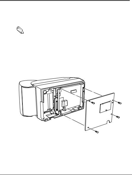
1.Make sure the power supply is disconnected from the printer.
2.Remove four screws from the bottom of the printer; then remove the cover.
1–2 Setting Up the Printer

3.Two spacers are included with the near-end detector. See the illustration below, and decide whether or not you want to use them. Use them if you want the near-end detector to be triggered when distance A is 3 to 4 mm (0.12 to 0.16”); otherwise it will be triggered when distance A is approximately 6 mm (0.24”).
 distance A
4.Secure the paper roll near-end detector (and spacers) with two screws. When you insert the spacers, be sure you set the spacers in the direction shown in the illustration.
Setting Up the Printer 1–3
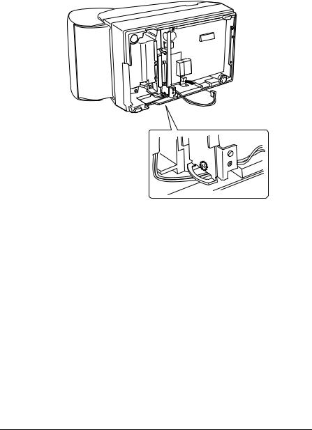
5.Connect the connector of the detector to CN11 on the printer. Position the cable as shown in the illustration.
6. Replace the cover and fasten it with the four screws.
1–4 Setting Up the Printer
Connecting the Printer to the Computer
You need an appropriate serial interface or parallel interface cable to connect your computer to the printer (null modem serial or IEEE 1284 parallel).
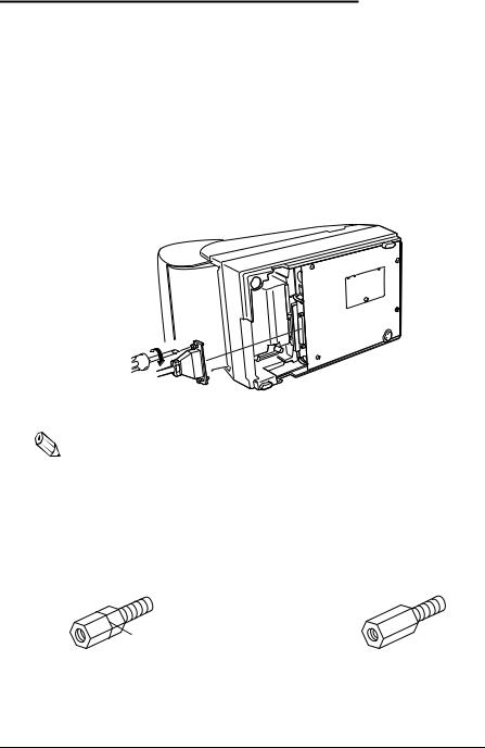
The Model with Serial Interface
1.Make sure the printer and computer are turned off. Then plug the cable into the connector on the printer, as shown.
Note:
Your printer comes with inch-type hexagonal lock screws installed. If you plan to use an interface cable that requires millimeter-type lock screws, replace the inch-type screws with the enclosed millimeter-type screws by using a hex screwdriver (5 mm). To distinguish between the two types of screws, see the illustration below.
Notch (one or more lines)
Inch-type |
Millimeter-type |
2.Connect the other end of the cable to the connector on your computer.
Setting Up the Printer 1–5
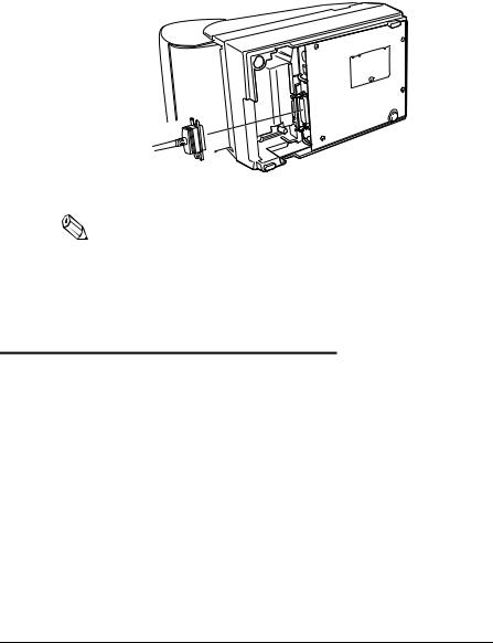
The Model with Parallel Interface
1.Make sure the printer and computer are turned off. Then, plug the cable into the connector on the printer, as shown.
Note:
Squeeze the wire clips on the printer together until they lock in place on both sides of the connector.
2.Connect the other end of the cable to the connector on your computer.
Connecting the Printer to the Drawer
 WARNING:
Use a drawer that matches printer specifications. Using an improper drawer may damage the drawer as well as the printer. (See Chapter 4 “Reference Information” for information on the drawer.
1–6 Setting Up the Printer

Plug the drawer cable into the drawer kick-out connector on the bottom of the printer next to the computer interface connector.
Model with
Serial Interface
Model with
Parallel Interface
 CAUTION:
Do not connect a telephone line to the drawer kick-out connector; otherwise the printer and the telephone line may be damaged.
Setting Up the Printer 1–7
Loading...