


 Loading...
Technical manual
TM-U200D/U200PD
Copied Date |
199 |
, |
, |
Copied by
English
4005680

Confidential
CONFIDENTIALITY AGREEMENT
BY USING THIS DOCUMENT, YOU AGREE TO ABIDE BY THE TERMS OF THIS AGREEMENT. PLEASE RETURN THIS DOCUMENT IMMEDIATELY IF YOU DO NOT AGREE TO THESE TERMS.
1.This document contains confidential, proprietary information of Seiko Epson Corporation or its affiliates. You must keep such information confidential. If the user is a business entity or organization, you must limit disclosure to those of your employees, agents and contractors who have a need to know and who are also bound by obligations of confidentiality.
2.On the earlier of (a) termination of your relationship with Seiko Epson, or (b) Seiko Epson’s request, you must stop using the confidential information. You must then return or destroy the information, as directed by Seiko Epson.
3.If a court, arbitrator, government agency or the like orders you to disclose any confidential information, you must immediately notify Seiko Epson. You agree to give Seiko Epson reasonable cooperation and assistance in resisting disclosure.
4.You may use confidential information only for the purpose of operating or servicing the products to which the document relates, unless you obtain the prior written consent of Seiko Epson for some other use.
5.Seiko Epson warrants that it has the right to disclose the confidential information. SEIKO EPSON MAKES NO OTHER WARRANTIES CONCERNING THE CONFIDENTIAL INFORMATION OR ANY OTHER INFORMATION IN THE DOCUMENT, INCLUDING (WITHOUT LIMITATION) ANY WARRANTY OF TITLE OR NON-INFRINGEMENT. Seiko Epson has no liability for loss or damage arising from or relating to your use of or reliance on the information on the document.
6.You may not reproduce, store or transmit the confidential information in any form or by any means (electronic, mechanical, photocopying, recording, or otherwise) without the prior written permission of Seiko Epson.
7.Your obligations under this Agreement are in addition to any other legal obligations. Seiko Epson does not waive any right under this Agreement by failing to exercise it. The laws of Japan apply to this Agreement.
CONFIDENTIAL
EPSON
SEIKO EPSON CORPORATION |
Printed in Japan E9608130-0000SE |

CONFIDENTIAL
TM-U200D/U200PD Technical Manual
FCC CLASS A
FCC Compliance Statement
For American Users
This equipment has been tested and found to comply with the limits for a Class A digital device, pursuant to Part 15 of the FCC Rules. These limits are designed to provide reasonable protection against harmful interference when the equipment is operated in a commercial environment.
This equipment generates, uses, and can radiate radio frequency energy and, if not installed and used in accordance with the instruction manual, may cause harmful interference to radio communications. Operation of this equipment in a residential area is likely to cause harmful interference, in which case the user will be required to correct the interference at his own expense.
WARNING
The connection of a non-shielded printer interface cable to this printer will invalidate the FCC Verification of this device and may cause interference levels which exceed the limits established by the FCC for this equipment.
You are cautioned that changes or modifications not expressly approved by the party responsible for compliance could void your authority to operate the equipment.
FOR CANADIAN USERS
This digital apparatus does not exceed the Class A limits for radio noise emissions from digital apparatus as set out in the radio interference regulations of the Canadian Department of Communications.
Le présent appareil numérique n’émet pas de bruits radioélectriques dépassant les limites applicables aux appareils numériques de Class A prescrites dans le règlement sur le brouillage radioélectrique édicté par le Ministère des Communications du Canada.
GEREÄUSCHPEGEL
Gemäß der Dritten Verordrung zum Gerätesicherheitsgecsetz (Maschinenlärminformations- Verordnung-3. GSGV) ist der arbeitsplatzbezogene Geräusch-Emissionswert kleiner als 70 dB(A) (basierend auf ISO 7779).
Rev. B |
i |

CONFIDENTIAL
Introduction
The TM-U200D and TM-U200PD are one-station printers for ECR and POS use which can be used for printing the results of weighing or measuring.
The main features of the TM-U200D and TM-U200PD printers are the following:
High-speed printing through logic-seeking control
Excellent reliability and long life due to use of two stepping motors, one for moving the carriage and one for paper feeding
Flexible paper feed setting permits printing in accordance with any user-defined format
Command protocol based on ESC/POS, a widely used standard
Built-in drawer kick-out interface provides capability to drive two drawers
Selectable character fonts (7 x 9, 9 x 9)
Semi-automatic paper loading capability
AC adapter (included) provides compact power supply
Compact and light in weight
Automatic Status Back (ASB) function to automatically send printer status changes.
Two-color printing. Black and red colors are selectable. (2-color Print Version only)
ii |
Rev. B |

CONFIDENTIAL
Notes and Cautions
Note:
Notes have important information and useful tips on the operation of your printer.
 CAUTION:
Cautions must be observed to avoid damage to your equipment.
Rev. B |
iii |

CONFIDENTIAL
Revision Sheet
Revision |
Page |
Altered Item and Contents |
|
|
|
Rev. B |
All |
Added information of the 2-color Print Version |
|
|
|
|
|
|
|
|
|
|
|
|
|
|
|
|
|
|
|
|
|
iv |
Rev. B |

CONFIDENTIAL
|
TM-U200D/U200PD Technical Manual |
|
Chapter 1 Features and General Specifications |
|
|
Features . . . . . . . . . . . . . . . . . . . . . . . . . . . . . . . . . . . . . . . . . . . . . . . . . . . . . . . . . . |
. . . . . . . . . . . . . . . . . . . . . . . . . . . . . . . . 1-3 |
|
Printing Specifications . . . . . . . . . . . . . . . . . . . . . . . . . . . . . . . . . . . . . . . . . |
. . . . . . . . . . . . . . . . . . . . . . . . . . . . . . . . 1-3 |
|
Character Specifications . . . . . . . . . . . . . . . . . . . . . . . . . . . . . . . . . . . . . . . . |
. . . . . . . . . . . . . . . . . . . . . . . . . . . . . . . . 1-4 |
|
Paper . . . . . . . . . . . . . . . . . . . . . . . . . . . . . . . . . . . . . . . . . . . . . . . . . . . . . . . . |
. . . . . . . . . . . . . . . . . . . . . . . . . . . . . . . . 1-6 |
|
Paper Roll Supply Device . . . . . . . . . . . . . . . . . . . . . . . . . . . . . . . . . . . . . . . |
. . . . . . . . . . . . . . . . . . . . . . . . . . . . . . . . 1-7 |
|
Receive Buffer . . . . . . . . . . . . . . . . . . . . . . . . . . . . . . . . . . . . . . . . . . . . . . . . |
. . . . . . . . . . . . . . . . . . . . . . . . . . . . . . . . 1-7 |
|
Electrical Specifications . . . . . . . . . . . . . . . . . . . . . . . . . . . . . . . . . . . . . . . . . |
. . . . . . . . . . . . . . . . . . . . . . . . . . . . . . . . 1-8 |
|
Ribbon Cassette . . . . . . . . . . . . . . . . . . . . . . . . . . . . . . . . . . . . . . . . . . . . . . . |
. . . . . . . . . . . . . . . . . . . . . . . . . . . . . . . . 1-8 |
|
External Dimensions and Weight . . . . . . . . . . . . . . . . . . . . . . . . . . . . . . . . |
. . . . . . . . . . . . . . . . . . . . . . . . . . . . . . . . 1-9 |
|
Environmental Specifications . . . . . . . . . . . . . . . . . . . . . . . . . . . . . . . . . . . |
. . . . . . . . . . . . . . . . . . . . . . . . . . . . . . . . 1-9 |
|
Reliability . . . . . . . . . . . . . . . . . . . . . . . . . . . . . . . . . . . . . . . . . . . . . . . . . . . . |
. . . . . . . . . . . . . . . . . . . . . . . . . . . . . . . . 1-10 |
|
Safety and EMI Standards Applied . . . . . . . . . . . . . . . . . . . . . . . . . . . . . . . |
. . . . . . . . . . . . . . . . . . . . . . . . . . . . . . . 1-10 |
|
Printer Installation Stance . . . . . . . . . . . . . . . . . . . . . . . . . . . . . . . . . . . . . . . |
. . . . . . . . . . . . . . . . . . . . . . . . . . . . . . . 1-10 |
|
Hardware Configuration . . . . . . . . . . . . . . . . . . . . . . . . . . . . . . . . . . . . . . . . . . . . |
. . . . . . . . . . . . . . . . . . . . . . . . . . . . . . . 1-11 |
|
Main Unit Specifications . . . . . . . . . . . . . . . . . . . . . . . . . . . . . . . . . . . . . . . . . . . . . |
. . . . . . . . . . . . . . . . . . . . . . . . . . . . . . . 1-12 |
|
Motor, Paper Feed . . . . . . . . . . . . . . . . . . . . . . . . . . . . . . . . . . . . . . . . . . . . . . |
. . . . . . . . . . . . . . . . . . . . . . . . . . . . . . . 1-12 |
|
Motor, Carriage . . . . . . . . . . . . . . . . . . . . . . . . . . . . . . . . . . . . . . . . . . . . . . . . |
. . . . . . . . . . . . . . . . . . . . . . . . . . . . . . . 1-12 |
|
Print Head Unit . . . . . . . . . . . . . . . . . . . . . . . . . . . . . . . . . . . . . . . . . . . . . . . . |
. . . . . . . . . . . . . . . . . . . . . . . . . . . . . . . 1-12 |
|
Detector Sub-ass’y . . . . . . . . . . . . . . . . . . . . . . . . . . . . . . . . . . . . . . . . . . . . . . |
. . . . . . . . . . . . . . . . . . . . . . . . . . . . . . . 1-12 |
|
Paper Detector Switch Sub-ass’y . . . . . . . . . . . . . . . . . . . . . . . . . . . . . . . . . . |
. . . . . . . . . . . . . . . . . . . . . . . . . . . . . . . 1-13 |
|
Near-end Detector (N.E.-U200); (Optional) . . . . . . . . . . . . . . . . . . . . . . . . . |
. . . . . . . . . . . . . . . . . . . . . . . . . . . . . . . 1-13 |
|
Connectors . . . . . . . . . . . . . . . . . . . . . . . . . . . . . . . . . . . . . . . . . . . . . . . . . . . . . . . . |
. . . . . . . . . . . . . . . . . . . . . . . . . . . . . . . 1-13 |
|
Interface Connector . . . . . . . . . . . . . . . . . . . . . . . . . . . . . . . . . . . . . . . . . . . . . |
. . . . . . . . . . . . . . . . . . . . . . . . . . . . . . . 1-13 |
|
Power Supply Connector . . . . . . . . . . . . . . . . . . . . . . . . . . . . . . . . . . . . . . . . |
. . . . . . . . . . . . . . . . . . . . . . . . . . . . . . . 1-14 |
|
Drawer Kick-Out Connector . . . . . . . . . . . . . . . . . . . . . . . . . . . . . . . . . . . . . |
. . . . . . . . . . . . . . . . . . . . . . . . . . . . . . . 1-14 |
|
Interface . . . . . . . . . . . . . . . . . . . . . . . . . . . . . . . . . . . . . . . . . . . . . . . . . . . . . . . . . . . |
. . . . . . . . . . . . . . . . . . . . . . . . . . . . . . . 1-16 |
|
RS-232 Serial Interface . . . . . . . . . . . . . . . . . . . . . . . . . . . . . . . . . . . . . . . . . . . |
. . . . . . . . . . . . . . . . . . . . . . . . . . . . . . . 1-16 |
|
Interface Connector Pin Assignments . . . . . . . . . . . . . . . . . . . . . . . . . . . . . |
. . . . . . . . . . . . . . . . . . . . . . . . . . . . . . . 1-17 |
|
RS-485 Serial Interface (option) . . . . . . . . . . . . . . . . . . . . . . . . . . . . . . . . . . . |
. . . . . . . . . . . . . . . . . . . . . . . . . . . . . . . 1-19 |
|
IEEE 1284 Parallel Interface . . . . . . . . . . . . . . . . . . . . . . . . . . . . . . . . . . . . . . |
. . . . . . . . . . . . . . . . . . . . . . . . . . . . . . . 1-19 |
|
Reverse Mode (Data Transmission from Printer to Host) . . . . . . . . . . . . . |
. . . . . . . . . . . . . . . . . . . . . . . . . . . . . . . 1-19 |
|
Interface Connector Pin Assignments . . . . . . . . . . . . . . . . . . . . . . . . . . . . . |
. . . . . . . . . . . . . . . . . . . . . . . . . . . . . . . 1-21 |
|
Buttons and Switches . . . . . . . . . . . . . . . . . . . . . . . . . . . . . . . . . . . . . . . . . . . . . . . |
. . . . . . . . . . . . . . . . . . . . . . . . . . . . . . . 1-24 |
|
Power Switch . . . . . . . . . . . . . . . . . . . . . . . . . . . . . . . . . . . . . . . . . . . . . . . . . . |
. . . . . . . . . . . . . . . . . . . . . . . . . . . . . . . 1-24 |
|
Panel Button . . . . . . . . . . . . . . . . . . . . . . . . . . . . . . . . . . . . . . . . . . . . . . . . . . . |
. . . . . . . . . . . . . . . . . . . . . . . . . . . . . . . 1-24 |
|
DIP Switches . . . . . . . . . . . . . . . . . . . . . . . . . . . . . . . . . . . . . . . . . . . . . . . . . . . |
. . . . . . . . . . . . . . . . . . . . . . . . . . . . . . . 1-25 |
|
Panel LEDs . . . . . . . . . . . . . . . . . . . . . . . . . . . . . . . . . . . . . . . . . . . . . . . . . . . . |
. . . . . . . . . . . . . . . . . . . . . . . . . . . . . . . 1-27 |
|
Self-test . . . . . . . . . . . . . . . . . . . . . . . . . . . . . . . . . . . . . . . . . . . . . . . . . . . . . . . . . . . |
. . . . . . . . . . . . . . . . . . . . . . . . . . . . . . . 1-27 |
|
Performing the Self Test . . . . . . . . . . . . . . . . . . . . . . . . . . . . . . . . . . . . . . . . . |
. . . . . . . . . . . . . . . . . . . . . . . . . . . . . . . 1-27 |
|
Error Processing . . . . . . . . . . . . . . . . . . . . . . . . . . . . . . . . . . . . . . . . . . . . . . . . . . . . |
. . . . . . . . . . . . . . . . . . . . . . . . . . . . . . . 1-28 |
|
Printer Operation When an Error Occurs . . . . . . . . . . . . . . . . . . . . . . . . . . |
. . . . . . . . . . . . . . . . . . . . . . . . . . . . . . . 1-28 |
|
Data Receive Error . . . . . . . . . . . . . . . . . . . . . . . . . . . . . . . . . . . . . . . . . . . . . . |
. . . . . . . . . . . . . . . . . . . . . . . . . . . . . . . 1-28 |
|
Buffer Full Printing . . . . . . . . . . . . . . . . . . . . . . . . . . . . . . . . . . . . . . . . . . . . . . . . . |
. . . . . . . . . . . . . . . . . . . . . . . . . . . . . . . 1-28 |
|
Detectors and Printing . . . . . . . . . . . . . . . . . . . . . . . . . . . . . . . . . . . . . . . . . . . . . . |
. . . . . . . . . . . . . . . . . . . . . . . . . . . . . . . 1-28 |
|
Hexadecimal Dump . . . . . . . . . . . . . . . . . . . . . . . . . . . . . . . . . . . . . . . . . . . . . . . . |
. . . . . . . . . . . . . . . . . . . . . . . . . . . . . . . 1-29 |
|
Hexadecimal Dump Function 1-29 |
|
|
Performing a Hexadecimal Dump . . . . . . . . . . . . . . . . . . . . . . . . . . . . . . . . |
. . . . . . . . . . . . . . . . . . . . . . . . . . . . . . . 1-29 |
|
Options . . . . . . . . . . . . . . . . . . . . . . . . . . . . . . . . . . . . . . . . . . . . . . . . . . . . . . . . . . . |
. . . . . . . . . . . . . . . . . . . . . . . . . . . . . . . 1-29 |
|
External Power Supply PS-170 . . . . . . . . . . . . . . . . . . . . . . . . . . . . . . . . . . . |
. . . . . . . . . . . . . . . . . . . . . . . . . . . . . . . 1-30 |
|
Rev. B |
-1 |

CONFIDENTIAL
Chapter 2 Mechanism Configuration and Operating Principles
Printer Mechanism Operating Principles . . . . . . . . . . . . . . . . . . . . . . . . . . . . . . . . . . . . . . . . . . . . . . . . . . . . . . . . . . . . . . . |
2-1 |
Print mechanism unit . . . . . . . . . . . . . . . . . . . . . . . . . . . . . . . . . . . . . . . . . . . . . . . . . . . . . . . . . . . . . . . . . . . . . . . . . . . |
2-2 |
Print head unit movement . . . . . . . . . . . . . . . . . . . . . . . . . . . . . . . . . . . . . . . . . . . . . . . . . . . . . . . . . . . . . . . . . . . . . . . |
2-3 |
Wire movement when a single dot is printed . . . . . . . . . . . . . . . . . . . . . . . . . . . . . . . . . . . . . . . . . . . . . . . . . . . . . . . |
2-3 |
Printing a character (9x9 font) . . . . . . . . . . . . . . . . . . . . . . . . . . . . . . . . . . . . . . . . . . . . . . . . . . . . . . . . . . . . . . . . . . . |
2-4 |
Paper Feed Mechanism Unit . . . . . . . . . . . . . . . . . . . . . . . . . . . . . . . . . . . . . . . . . . . . . . . . . . . . . . . . . . . . . . . . . . . . . |
2-5 |
Paper loading (semi-automatic loading) . . . . . . . . . . . . . . . . . . . . . . . . . . . . . . . . . . . . . . . . . . . . . . . . . . . . . . . . . . . |
2-6 |
Paper feeding . . . . . . . . . . . . . . . . . . . . . . . . . . . . . . . . . . . . . . . . . . . . . . . . . . . . . . . . . . . . . . . . . . . . . . . . . . . . . . . . . . |
2-6 |
Ribbon Feed Mechanism Unit . . . . . . . . . . . . . . . . . . . . . . . . . . . . . . . . . . . . . . . . . . . . . . . . . . . . . . . . . . . . . . . . . . . . |
2-7 |
Ribbon feeding . . . . . . . . . . . . . . . . . . . . . . . . . . . . . . . . . . . . . . . . . . . . . . . . . . . . . . . . . . . . . . . . . . . . . . . . . . . . . . . . . |
2-7 |
Detection Mechanism Unit . . . . . . . . . . . . . . . . . . . . . . . . . . . . . . . . . . . . . . . . . . . . . . . . . . . . . . . . . . . . . . . . . . . . . . |
2-9 |
Home position detection mechanism . . . . . . . . . . . . . . . . . . . . . . . . . . . . . . . . . . . . . . . . . . . . . . . . . . . . . . . . . . . . . . |
2-9 |
Paper detection mechanism . . . . . . . . . . . . . . . . . . . . . . . . . . . . . . . . . . . . . . . . . . . . . . . . . . . . . . . . . . . . . . . . . . . . . . |
2-10 |
Near-end detection mechanism (optional) . . . . . . . . . . . . . . . . . . . . . . . . . . . . . . . . . . . . . . . . . . . . . . . . . . . . . . . . . |
2-10 |
Ribbon Switch Mechanism Unit . . . . . . . . . . . . . . . . . . . . . . . . . . . . . . . . . . . . . . . . . . . . . . . . . . . . . . . . . . . . . . . . . . . . . . |
2-10 |
Switching from Black to Red . . . . . . . . . . . . . . . . . . . . . . . . . . . . . . . . . . . . . . . . . . . . . . . . . . . . . . . . . . . . . . . . . . . . . |
2-11 |
Releasing from Red to Black . . . . . . . . . . . . . . . . . . . . . . . . . . . . . . . . . . . . . . . . . . . . . . . . . . . . . . . . . . . . . . . . . . . . . |
2-11 |
Electrical Circuitry Operating Principles . . . . . . . . . . . . . . . . . . . . . . . . . . . . . . . . . . . . . . . . . . . . . . . . . . . . . . . . . . . . . . . |
2-12 |
Hardware Configuration . . . . . . . . . . . . . . . . . . . . . . . . . . . . . . . . . . . . . . . . . . . . . . . . . . . . . . . . . . . . . . . . . . . . . . . . |
2-12 |
Principles of Operation . . . . . . . . . . . . . . . . . . . . . . . . . . . . . . . . . . . . . . . . . . . . . . . . . . . . . . . . . . . . . . . . . . . . . . . . . . . . . . |
2-16 |
Power Supply Circuitry . . . . . . . . . . . . . . . . . . . . . . . . . . . . . . . . . . . . . . . . . . . . . . . . . . . . . . . . . . . . . . . . . . . . . . . . . |
2-16 |
Control Circuitry . . . . . . . . . . . . . . . . . . . . . . . . . . . . . . . . . . . . . . . . . . . . . . . . . . . . . . . . . . . . . . . . . . . . . . . . . . . . . . . |
2-17 |
CPU . . . . . . . . . . . . . . . . . . . . . . . . . . . . . . . . . . . . . . . . . . . . . . . . . . . . . . . . . . . . . . . . . . . . . . . . . . . . . . . . . . . . . . . . . . |
2-18 |
Various detector circuits . . . . . . . . . . . . . . . . . . . . . . . . . . . . . . . . . . . . . . . . . . . . . . . . . . . . . . . . . . . . . . . . . . . . . . . . . |
2-22 |
Host interface circuit . . . . . . . . . . . . . . . . . . . . . . . . . . . . . . . . . . . . . . . . . . . . . . . . . . . . . . . . . . . . . . . . . . . . . . . . . . . . |
2-23 |
Drawer kick-out drive circuit . . . . . . . . . . . . . . . . . . . . . . . . . . . . . . . . . . . . . . . . . . . . . . . . . . . . . . . . . . . . . . . . . . . . |
2-23 |
DIP switch read circuit . . . . . . . . . . . . . . . . . . . . . . . . . . . . . . . . . . . . . . . . . . . . . . . . . . . . . . . . . . . . . . . . . . . . . . . . . . |
2-24 |
Printer Mechanism Drive Circuit . . . . . . . . . . . . . . . . . . . . . . . . . . . . . . . . . . . . . . . . . . . . . . . . . . . . . . . . . . . . . . . . . . . . . |
2-25 |
Print head drive circuit . . . . . . . . . . . . . . . . . . . . . . . . . . . . . . . . . . . . . . . . . . . . . . . . . . . . . . . . . . . . . . . . . . . . . . . . . . |
2-25 |
Chapter 3 Handling and Maintenance
Handling Precautions . . . . . . . . . . . . . . . . . . . . . . . . . . . . . . . . . . . . . . . . . . . . . . . . . . . . . . . . . . . . . . . . . . . . . . . . . . . . . . . 3-1 Storage Precautions . . . . . . . . . . . . . . . . . . . . . . . . . . . . . . . . . . . . . . . . . . . . . . . . . . . . . . . . . . . . . . . . . . . . . . . . . . . . . 3-1 Use Precautions . . . . . . . . . . . . . . . . . . . . . . . . . . . . . . . . . . . . . . . . . . . . . . . . . . . . . . . . . . . . . . . . . . . . . . . . . . . . . . . . 3-1 Paper Handling Precautions . . . . . . . . . . . . . . . . . . . . . . . . . . . . . . . . . . . . . . . . . . . . . . . . . . . . . . . . . . . . . . . . . . . . . . 3-1 Ribbon Cassette Handling Precautions . . . . . . . . . . . . . . . . . . . . . . . . . . . . . . . . . . . . . . . . . . . . . . . . . . . . . . . . . . . . . 3-2
Replacing the Paper Roll . . . . . . . . . . . . . . . . . . . . . . . . . . . . . . . . . . . . . . . . . . . . . . . . . . . . . . . . . . . . . . . . . . . . . . . . . . . . . 3-2 Replacing the Ribbon Cassette . . . . . . . . . . . . . . . . . . . . . . . . . . . . . . . . . . . . . . . . . . . . . . . . . . . . . . . . . . . . . . . . . . . . . . . . 3-4 Removing Jammed Paper . . . . . . . . . . . . . . . . . . . . . . . . . . . . . . . . . . . . . . . . . . . . . . . . . . . . . . . . . . . . . . . . . . . . . . . . . . . . 3-6 Using the Power switch cover . . . . . . . . . . . . . . . . . . . . . . . . . . . . . . . . . . . . . . . . . . . . . . . . . . . . . . . . . . . . . . . . . . . . . . . . 3-8 Maintenance . . . . . . . . . . . . . . . . . . . . . . . . . . . . . . . . . . . . . . . . . . . . . . . . . . . . . . . . . . . . . . . . . . . . . . . . . . . . . . . . . . . . . . . 3-8
Periodic Checks . . . . . . . . . . . . . . . . . . . . . . . . . . . . . . . . . . . . . . . . . . . . . . . . . . . . . . . . . . . . . . . . . . . . . . . . . . . . . . . . 3-8 Cleaning . . . . . . . . . . . . . . . . . . . . . . . . . . . . . . . . . . . . . . . . . . . . . . . . . . . . . . . . . . . . . . . . . . . . . . . . . . . . . . . . . . . . . . . . . . . 3-9 Lubricants . . . . . . . . . . . . . . . . . . . . . . . . . . . . . . . . . . . . . . . . . . . . . . . . . . . . . . . . . . . . . . . . . . . . . . . . . . . . . . . . . . . . . . . . . 3-9 Lubrication Standard . . . . . . . . . . . . . . . . . . . . . . . . . . . . . . . . . . . . . . . . . . . . . . . . . . . . . . . . . . . . . . . . . . . . . . . . . . . . 3-9 Lubricants . . . . . . . . . . . . . . . . . . . . . . . . . . . . . . . . . . . . . . . . . . . . . . . . . . . . . . . . . . . . . . . . . . . . . . . . . . . . . . . . . . . . . 3-9 Lubrication Points . . . . . . . . . . . . . . . . . . . . . . . . . . . . . . . . . . . . . . . . . . . . . . . . . . . . . . . . . . . . . . . . . . . . . . . . . . . . . . 3-10
-2 |
Rev.B |

CONFIDENTIAL
TM-U200D/U200PD Technical Manual
Chapter 4 Troubleshooting
Self-test . . . . . . . . . . . . . . . . . . . . . . . . . . . . . . . . . . . . . . . . . . . . . . . . . . . . . . . . . . . . . . . . . . . . . . . . . . . . . . . . . . . . . . . . . . . 4-1
Initiating the Self-test . . . . . . . . . . . . . . . . . . . . . . . . . . . . . . . . . . . . . . . . . . . . . . . . . . . . . . . . . . . . . . . . . . . . . . . . . . . 4-1
Self-test Standby . . . . . . . . . . . . . . . . . . . . . . . . . . . . . . . . . . . . . . . . . . . . . . . . . . . . . . . . . . . . . . . . . . . . . . . . . . . . . . . 4-1
Ending the Self-test . . . . . . . . . . . . . . . . . . . . . . . . . . . . . . . . . . . . . . . . . . . . . . . . . . . . . . . . . . . . . . . . . . . . . . . . . . . . . 4-2
Troubleshooting Flowchart . . . . . . . . . . . . . . . . . . . . . . . . . . . . . . . . . . . . . . . . . . . . . . . . . . . . . . . . . . . . . . . . . . . . . . . . . . 4-3
Troubleshooting Tables . . . . . . . . . . . . . . . . . . . . . . . . . . . . . . . . . . . . . . . . . . . . . . . . . . . . . . . . . . . . . . . . . . . . . . . . . . . . . 4-9
Error Types and Countermeasures . . . . . . . . . . . . . . . . . . . . . . . . . . . . . . . . . . . . . . . . . . . . . . . . . . . . . . . . . . . . . . . . . . . . 4-14
Chapter 5 Disassembly, Assembly, and Adjustment
Small Part Specifications . . . . . . . . . . . . . . . . . . . . . . . . . . . . . . . . . . . . . . . . . . . . . . . . . . . . . . . . . . . . . . . . . . . . . . . . . . . . . |
5-1 |
Disassembly . . . . . . . . . . . . . . . . . . . . . . . . . . . . . . . . . . . . . . . . . . . . . . . . . . . . . . . . . . . . . . . . . . . . . . . . . . . . . . . . . . . . . . . |
5-2 |
Removing the fuse . . . . . . . . . . . . . . . . . . . . . . . . . . . . . . . . . . . . . . . . . . . . . . . . . . . . . . . . . . . . . . . . . . . . . . . . . . . . . . |
5-2 |
Sub-assembly A . . . . . . . . . . . . . . . . . . . . . . . . . . . . . . . . . . . . . . . . . . . . . . . . . . . . . . . . . . . . . . . . . . . . . . . . . . . . . . . . . . . . |
5-3 |
Frame, paper feed unit ass’y . . . . . . . . . . . . . . . . . . . . . . . . . . . . . . . . . . . . . . . . . . . . . . . . . . . . . . . . . . . . . . . . . . . . . |
5-3 |
Main Assembly 1 . . . . . . . . . . . . . . . . . . . . . . . . . . . . . . . . . . . . . . . . . . . . . . . . . . . . . . . . . . . . . . . . . . . . . . . . . . . . . . . . . . . |
5-8 |
Lever, ribbon switch , Spring, ribbon release , Lever, ribbon release , Gear, ribbon intermediate, |
|
Gear, ribbon transmission , Ribbon take-up ass’y , and Plate, ribbon drive ass’y. . . . . . . . . . . . . . . . . . . . . . . . . |
5-8 |
Main Assembly 2 . . . . . . . . . . . . . . . . . . . . . . . . . . . . . . . . . . . . . . . . . . . . . . . . . . . . . . . . . . . . . . . . . . . . . . . . . . . . . . . . . . . |
5-10 |
Tension plate ass’y . . . . . . . . . . . . . . . . . . . . . . . . . . . . . . . . . . . . . . . . . . . . . . . . . . . . . . . . . . . . . . . . . . . . . . . . . . . . . . |
5-10 |
Main Assembly 3 . . . . . . . . . . . . . . . . . . . . . . . . . . . . . . . . . . . . . . . . . . . . . . . . . . . . . . . . . . . . . . . . . . . . . . . . . . . . . . . . . . . |
5-10 |
Frame, paper feed ass’y . . . . . . . . . . . . . . . . . . . . . . . . . . . . . . . . . . . . . . . . . . . . . . . . . . . . . . . . . . . . . . . . . . . . . . . . . |
5-10 |
Main Assembly 4 . . . . . . . . . . . . . . . . . . . . . . . . . . . . . . . . . . . . . . . . . . . . . . . . . . . . . . . . . . . . . . . . . . . . . . . . . . . . . . . . . . . |
5-11 |
Motor, carriage ass’y . . . . . . . . . . . . . . . . . . . . . . . . . . . . . . . . . . . . . . . . . . . . . . . . . . . . . . . . . . . . . . . . . . . . . . . . . . . . |
5-11 |
Main Assembly 5 . . . . . . . . . . . . . . . . . . . . . . . . . . . . . . . . . . . . . . . . . . . . . . . . . . . . . . . . . . . . . . . . . . . . . . . . . . . . . . . . . . . |
5-12 |
Carriage sub-ass’y . . . . . . . . . . . . . . . . . . . . . . . . . . . . . . . . . . . . . . . . . . . . . . . . . . . . . . . . . . . . . . . . . . . . . . . . . . . . . . |
5-12 |
Main Assembly 6 . . . . . . . . . . . . . . . . . . . . . . . . . . . . . . . . . . . . . . . . . . . . . . . . . . . . . . . . . . . . . . . . . . . . . . . . . . . . . . . . . . . |
5-13 |
Shaft, carriage ass’y . . . . . . . . . . . . . . . . . . . . . . . . . . . . . . . . . . . . . . . . . . . . . . . . . . . . . . . . . . . . . . . . . . . . . . . . . . . . . |
5-13 |
Main Assembly 7 . . . . . . . . . . . . . . . . . . . . . . . . . . . . . . . . . . . . . . . . . . . . . . . . . . . . . . . . . . . . . . . . . . . . . . . . . . . . . . . . . . . |
5-14 |
Shaft holder, adjusting roller . . . . . . . . . . . . . . . . . . . . . . . . . . . . . . . . . . . . . . . . . . . . . . . . . . . . . . . . . . . . . . . . . . . . . |
5-14 |
Main Assembly 8 . . . . . . . . . . . . . . . . . . . . . . . . . . . . . . . . . . . . . . . . . . . . . . . . . . . . . . . . . . . . . . . . . . . . . . . . . . . . . . . . . . . |
5-15 |
Shaft, carriage guide ass’y . . . . . . . . . . . . . . . . . . . . . . . . . . . . . . . . . . . . . . . . . . . . . . . . . . . . . . . . . . . . . . . . . . . . . . . |
5-15 |
Main Assembly 9 . . . . . . . . . . . . . . . . . . . . . . . . . . . . . . . . . . . . . . . . . . . . . . . . . . . . . . . . . . . . . . . . . . . . . . . . . . . . . . . . . . . |
5-15 |
Spring, belt tension ass’y . . . . . . . . . . . . . . . . . . . . . . . . . . . . . . . . . . . . . . . . . . . . . . . . . . . . . . . . . . . . . . . . . . . . . . . . |
5-15 |
Main Assembly 10 . . . . . . . . . . . . . . . . . . . . . . . . . . . . . . . . . . . . . . . . . . . . . . . . . . . . . . . . . . . . . . . . . . . . . . . . . . . . . . . . . . |
5-16 |
Detector sub-ass’y . . . . . . . . . . . . . . . . . . . . . . . . . . . . . . . . . . . . . . . . . . . . . . . . . . . . . . . . . . . . . . . . . . . . . . . . . . . . . . |
5-16 |
Main Assembly 11 . . . . . . . . . . . . . . . . . . . . . . . . . . . . . . . . . . . . . . . . . . . . . . . . . . . . . . . . . . . . . . . . . . . . . . . . . . . . . . . . . . |
5-17 |
Radiating plate, carriage motor . . . . . . . . . . . . . . . . . . . . . . . . . . . . . . . . . . . . . . . . . . . . . . . . . . . . . . . . . . . . . . . . . . . |
5-17 |
Main Assembly 12 . . . . . . . . . . . . . . . . . . . . . . . . . . . . . . . . . . . . . . . . . . . . . . . . . . . . . . . . . . . . . . . . . . . . . . . . . . . . . . . . . . |
5-18 |
FFC, print head ass’y ( Single-color Print Version only) . . . . . . . . . . . . . . . . . . . . . . . . . . . . . . . . . . . . . . . . . . . . . . |
5-18 |
FPC, print head ass’y (2-color Print Version only) . . . . . . . . . . . . . . . . . . . . . . . . . . . . . . . . . . . . . . . . . . . . . . . . . . . |
5-19 |
Main Assembly 13 . . . . . . . . . . . . . . . . . . . . . . . . . . . . . . . . . . . . . . . . . . . . . . . . . . . . . . . . . . . . . . . . . . . . . . . . . . . . . . . . . . |
5-20 |
Print head ground plate and Print head unit (Single-color Print Version only) . . . . . . . . . . . . . . . . . . . . . . . . . . |
5-20 |
Print head unit (2-color Print Version only) . . . . . . . . . . . . . . . . . . . . . . . . . . . . . . . . . . . . . . . . . . . . . . . . . . . . . . . . |
5-21 |
Main Assembly 14 . . . . . . . . . . . . . . . . . . . . . . . . . . . . . . . . . . . . . . . . . . . . . . . . . . . . . . . . . . . . . . . . . . . . . . . . . . . . . . . . . . |
5-23 |
Fame, ribbon knob and Frame, ribbon ass’y (Single-color Print Version only) . . . . . . . . . . . . . . . . . . . . . . . . . . . |
5-23 |
Main assembly 15 . . . . . . . . . . . . . . . . . . . . . . . . . . . . . . . . . . . . . . . . . . . . . . . . . . . . . . . . . . . . . . . . . . . . . . . . . . . . . . . . . . |
5-24 |
Fixing plate, cover, left and Fixing plate, cover, right (2-color Print Version) . . . . . . . . . . . . . . . . . . . . . . . . . . . . |
5-24 |
Main Assembly 16 . . . . . . . . . . . . . . . . . . . . . . . . . . . . . . . . . . . . . . . . . . . . . . . . . . . . . . . . . . . . . . . . . . . . . . . . . . . . . . . . . . |
5-25 |
Earth plate, ribbon frame (2-color Print Version only) . . . . . . . . . . . . . . . . . . . . . . . . . . . . . . . . . . . . . . . . . . . . . . . |
5-25 |
Main Assembly 17 . . . . . . . . . . . . . . . . . . . . . . . . . . . . . . . . . . . . . . . . . . . . . . . . . . . . . . . . . . . . . . . . . . . . . . . . . . . . . . . . . . |
5-26 |
Frame, ribbon ass’y, Spring, ribbon frame and Fixing plate, ribbon frame (2-color Print Version only) . . . . . . |
5-26 |
Main Assembly 18 . . . . . . . . . . . . . . . . . . . . . . . . . . . . . . . . . . . . . . . . . . . . . . . . . . . . . . . . . . . . . . . . . . . . . . . . . . . . . . . . . . |
5-27 |
Thumb-screw and Cover, head (2-color Print Version only) . . . . . . . . . . . . . . . . . . . . . . . . . . . . . . . . . . . . . . . . . . |
5-27 |
Main Assembly 1 (Case Unit) . . . . . . . . . . . . . . . . . . . . . . . . . . . . . . . . . . . . . . . . . . . . . . . . . . . . . . . . . . . . . . . . . . . . . . . . |
5-28 |
Rev. B |
-3 |
CONFIDENTIAL
Plate, cutter, lower . . . . . . . . . . . . . . . . . . . . . . . . . . . . . . . . . . . . . . . . . . . . . . . . . . . . . . . . . . . . . . . . . . . . . . . . . . . . . . 5-28 Main Assembly 2 (Case Unit) . . . . . . . . . . . . . . . . . . . . . . . . . . . . . . . . . . . . . . . . . . . . . . . . . . . . . . . . . . . . . . . . . . . . . . . . . 5-29 Plate, upper . . . . . . . . . . . . . . . . . . . . . . . . . . . . . . . . . . . . . . . . . . . . . . . . . . . . . . . . . . . . . . . . . . . . . . . . . . . . . . . . . . . . 5-29 Main Assembly 3 (Case Unit) . . . . . . . . . . . . . . . . . . . . . . . . . . . . . . . . . . . . . . . . . . . . . . . . . . . . . . . . . . . . . . . . . . . . . . . . . 5-30 Main circuit board ass’y . . . . . . . . . . . . . . . . . . . . . . . . . . . . . . . . . . . . . . . . . . . . . . . . . . . . . . . . . . . . . . . . . . . . . . . . . 5-30 Main Assembly 4 (Case Unit) . . . . . . . . . . . . . . . . . . . . . . . . . . . . . . . . . . . . . . . . . . . . . . . . . . . . . . . . . . . . . . . . . . . . . . . . . 5-32 Inserting the cables . . . . . . . . . . . . . . . . . . . . . . . . . . . . . . . . . . . . . . . . . . . . . . . . . . . . . . . . . . . . . . . . . . . . . . . . . . . . . . 5-32 Main Assembly 5 (Case Unit) . . . . . . . . . . . . . . . . . . . . . . . . . . . . . . . . . . . . . . . . . . . . . . . . . . . . . . . . . . . . . . . . . . . . . . . . . 5-32 Case, lower . . . . . . . . . . . . . . . . . . . . . . . . . . . . . . . . . . . . . . . . . . . . . . . . . . . . . . . . . . . . . . . . . . . . . . . . . . . . . . . . . . . . 5-32 Main Assembly 6 (Case Unit) . . . . . . . . . . . . . . . . . . . . . . . . . . . . . . . . . . . . . . . . . . . . . . . . . . . . . . . . . . . . . . . . . . . . . . . . . 5-34 Manual cutter . . . . . . . . . . . . . . . . . . . . . . . . . . . . . . . . . . . . . . . . . . . . . . . . . . . . . . . . . . . . . . . . . . . . . . . . . . . . . . . . . . 5-34 Main Assembly 7 (Case Unit) . . . . . . . . . . . . . . . . . . . . . . . . . . . . . . . . . . . . . . . . . . . . . . . . . . . . . . . . . . . . . . . . . . . . . . . . . 5-35 Paper roll receive rollers, Case, upper, Roller, guide and Switch panel . . . . . . . . . . . . . . . . . . . . . . . . . . . . . . . . . 5-35 Main Assembly 8 (Case Unit) . . . . . . . . . . . . . . . . . . . . . . . . . . . . . . . . . . . . . . . . . . . . . . . . . . . . . . . . . . . . . . . . . . . . . . . . . 5-37 Interface circuit board ass’y and Connector plate . . . . . . . . . . . . . . . . . . . . . . . . . . . . . . . . . . . . . . . . . . . . . . . . . . . . 5-37 Main Assembly 9 (Case Unit) . . . . . . . . . . . . . . . . . . . . . . . . . . . . . . . . . . . . . . . . . . . . . . . . . . . . . . . . . . . . . . . . . . . . . . . . . 5-38 Plate, lower, Cover, ROM, and Rubber foot . . . . . . . . . . . . . . . . . . . . . . . . . . . . . . . . . . . . . . . . . . . . . . . . . . . . . . . . . 5-38 Main Assembly 10 (Case Unit) . . . . . . . . . . . . . . . . . . . . . . . . . . . . . . . . . . . . . . . . . . . . . . . . . . . . . . . . . . . . . . . . . . . . . . . . 5-40 Caution seal AB (Single-color Print Version only) . . . . . . . . . . . . . . . . . . . . . . . . . . . . . . . . . . . . . . . . . . . . . . . . . . . 5-40 Main Assembly 11 (Case Unit) . . . . . . . . . . . . . . . . . . . . . . . . . . . . . . . . . . . . . . . . . . . . . . . . . . . . . . . . . . . . . . . . . . . . . . . . 5-41
Cover, main and Hinge ass’y (There are two type printers, which are either with or without the
Hinge ass’y) . . . . . . . . . . . . . . . . . . . . . . . . . . . . . . . . . . . . . . . . . . . . . . . . . . . . . . . . . . . . . . . . . . . . . . . . . . . . . . . . . . . . 5-41 Near-end detector ass’y(N.E-U200); (optional) . . . . . . . . . . . . . . . . . . . . . . . . . . . . . . . . . . . . . . . . . . . . . . . . . . . . . . 5-43 Adjustment . . . . . . . . . . . . . . . . . . . . . . . . . . . . . . . . . . . . . . . . . . . . . . . . . . . . . . . . . . . . . . . . . . . . . . . . . . . . . . . . . . . . . . . . 5-45 Platen gap adjustment . . . . . . . . . . . . . . . . . . . . . . . . . . . . . . . . . . . . . . . . . . . . . . . . . . . . . . . . . . . . . . . . . . . . . . . . . . . 5-45
Appendix
RS-485 Serial Interface . . . . . . . . . . . . . . . . . . . . . . . . . . . . . . . . . . . . . . . . . . . . . . . . . . . . . . . . . . . . . . . . . . . . . . . . . . . . . . . |
A-1 |
XON/XOFF Transmit Timing . . . . . . . . . . . . . . . . . . . . . . . . . . . . . . . . . . . . . . . . . . . . . . . . . . . . . . . . . . . . . . . . . . . . |
A-4 |
Data Format When Using RS-485 . . . . . . . . . . . . . . . . . . . . . . . . . . . . . . . . . . . . . . . . . . . . . . . . . . . . . . . . . . . . . . . . . |
A-4 |
Main Circuit Board A Parts Layout . . . . . . . . . . . . . . . . . . . . . . . . . . . . . . . . . . . . . . . . . . . . . . . . . . . . . . . . . . . . . . . . . . . |
A-6 |
Main Circuit Board C Parts Layout . . . . . . . . . . . . . . . . . . . . . . . . . . . . . . . . . . . . . . . . . . . . . . . . . . . . . . . . . . . . . . . . . . . |
A-7 |
RS-232 Serial Interface Circuit Board Parts Layout . . . . . . . . . . . . . . . . . . . . . . . . . . . . . . . . . . . . . . . . . . . . . . . . . . . . . . . |
A-8 |
IEEE 1284 Parallel Interface Circuit Board Parts Layout . . . . . . . . . . . . . . . . . . . . . . . . . . . . . . . . . . . . . . . . . . . . . . . . . . |
A-9 |
RS-485 Serial Interface Circuit Board Parts Layout . . . . . . . . . . . . . . . . . . . . . . . . . . . . . . . . . . . . . . . . . . . . . . . . . . . . . . . |
A-10 |
Main Circuit Board C Diagram . . . . . . . . . . . . . . . . . . . . . . . . . . . . . . . . . . . . . . . . . . . . . . . . . . . . . . . . . . . . . . . . . . . . . . . |
A-12 |
RS-232 Serial Interface Circuit Board Diagram . . . . . . . . . . . . . . . . . . . . . . . . . . . . . . . . . . . . . . . . . . . . . . . . . . . . . . . . . . |
A-13 |
IEEE 1284 Parallel Interface Circuit Board Diagram . . . . . . . . . . . . . . . . . . . . . . . . . . . . . . . . . . . . . . . . . . . . . . . . . . . . . . |
A-14 |
RS-485 Serial Interface Circuit Board Diagram . . . . . . . . . . . . . . . . . . . . . . . . . . . . . . . . . . . . . . . . . . . . . . . . . . . . . . . . . . |
A-15 |
Printer Mechanism Unit Overall Exploded Diagram (Single-color Print Version) . . . . . . . . . . . . . . . . . . . . . . . . . . . . |
A-16 |
Printer Mechanism Unit Overall Exploded Diagram (2-color Print Version) . . . . . . . . . . . . . . . . . . . . . . . . . . . . . . . . . |
A-17 |
Case Unit Overall Exploded Diagram (Single-color Print Version) . . . . . . . . . . . . . . . . . . . . . . . . . . . . . . . . . . . . . . . . . |
A-18 |
Case Unit Overall Exploded Diagram (2-color Print Version) . . . . . . . . . . . . . . . . . . . . . . . . . . . . . . . . . . . . . . . . . . . . . |
A-19 |
Printer Mechanism Unit Lubrication Points Diagram (Single-color Print Version) . . . . . . . . . . . . . . . . . . . . . . . . . . . |
A-20 |
Case Unit Lubrication Points Diagram (2-color Print Version) . . . . . . . . . . . . . . . . . . . . . . . . . . . . . . . . . . . . . . . . . . . . . |
A-21 |
Case Unit Lubrication Points Diagram . . . . . . . . . . . . . . . . . . . . . . . . . . . . . . . . . . . . . . . . . . . . . . . . . . . . . . . . . . . . . . . . . |
A-22 |
-4 |
Rev.B |
CONFIDENTIAL
TM-U200D/U200PD Technical Manual
Chapter 1
Features and General Specifications
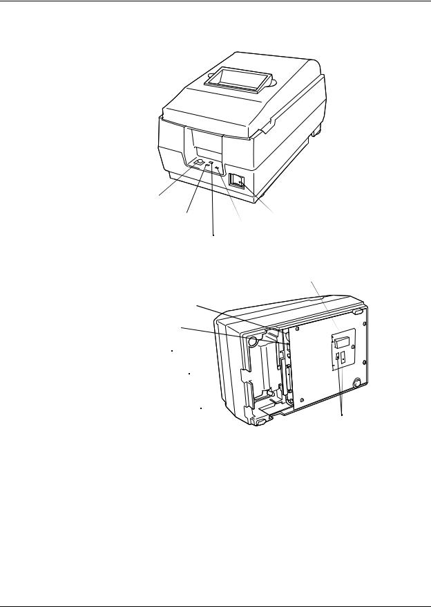
FEED button
ERROR LED |
Power switch |
|
POWER LED |
PAPER OUT LED
(PAPER OUT/PRESS FEED)
P-ROM
Power supply connector 
Drawer kick-out connector 
Frame ground screw
Interface connector 
Frame ground screw 
DIP switches
Figure 1-1 TM-U200D/U200PD appearance
Rev. B |
Features and General Specifications 1-1 |
CONFIDENTIAL
Features
Printing Specifications
Printing method: |
Serial impact dot-matrix |
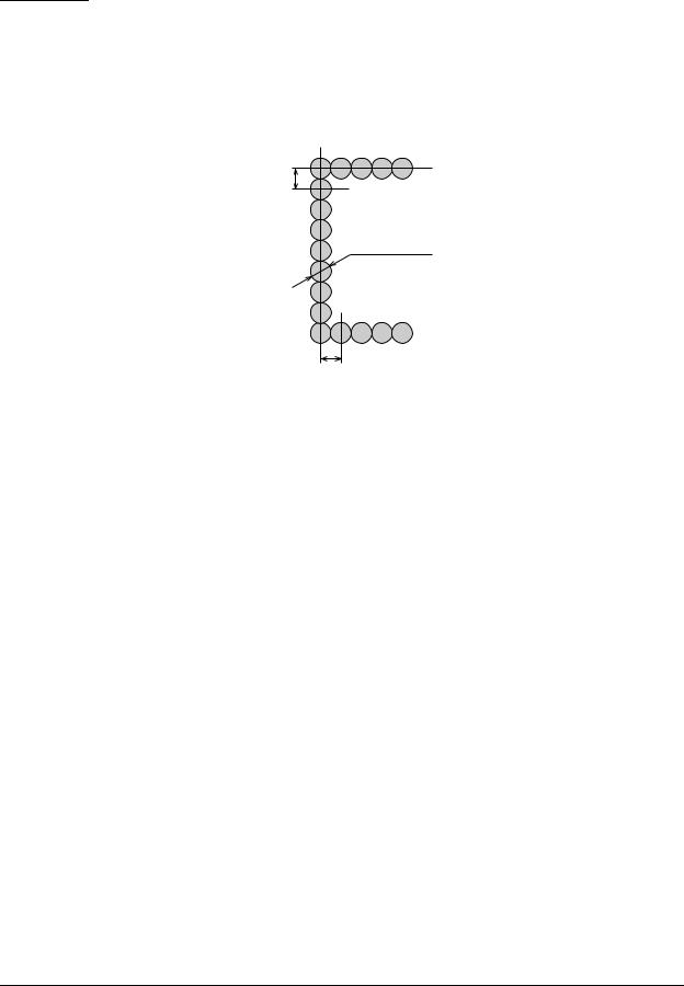
Head wire configuration: |
9-pin serial type |
0.353 mm (0.014")
0.29 mm (0.01") (wire diameter)
|
0.317 mm (0.012") |
|
Figure 1-2 Dot configuration |
Dot pitch: |
0.353 mm (1/72") |
Dot wire diameter |
0.29 mm (0.01") |
Printing direction: |
Bidirectional logic seeking |
Printing width: |
63.34 mm (2.49") |
Line feed: |
4.23 mm (1/6"): default setting |
|
Programmable in units of 1/144 inch by using commands. |
Paper feed method |
Friction feed |
Paper feed speed: |
Approximately 4.17 inches/second (25 lines/second) during |
|
continuous paper feeding |
Characters per line: |
See the table in the next page. |
Characters per inch: |
See the table in the next page. |
Total dot count (horizontal |
7 x 9 font: 400 half-dot positions per line |
direction) |
9 x 9 font: 400 half-dot positions per line |
Printing speed |
Approximately 3.5 lines/second (40 columns, 16 CPI) |
|
Approximately 6.4 lines/second (16 columns, 16 CPI) |
NOTE: If the printing duty ratio is too high, the operation of the print head is stopped by the duty limit. In such circumstances, the printing speeds shown above cannot be guranteed.
When select red-color or 2-colors(black and red) printing, the printing speed goes down compared with black-color printing. It is caused by the switching operation in the printer.
1-2 Features and General Specifications |
Rev.B |

CONFIDENTIAL
TM-U200D/U200PD Technical Manual
CPI = Characters per inch
Character dimensions, characters per inch, characters per line
Character Structure |
Character |
Character |
Dot Spacing |
Characters Per |
Characters Per |
|
Structure |
Dimensions |
Between |
||||
Horizontal x Vertical |
Line (CPL) |
Inch (CPI) |
||||
Character Set |
WxH |
Characters |
||||
|
|
|
||||
|
|
|
|
|
|
|
|
ANK |
1.2 x 3.1 mm |
3 half-dots |
40 |
16 |
|
|
(.047 x .122") |
|||||
7 x 9 |
|
|
|
|
||
|
|
|
|
|
||
Graphics |
1.7 x 3.1 mm |
0 |
40 |
16 |
||
|
||||||
|
(.070 x .122") |
|||||
|
|
|
|
|
||
|
|
|
|
|
|
|
|
ANK |
1.6 x 3.1 mm |
3 half-dots |
33 |
13.3 |
|
|
(.063 x .122") |
|||||
9 x 9 |
|
|
|
|
||
|
|
|
|
|
||
Graphics |
2.0 x 3.1 mm |
0 |
33 |
13.3 |
||
|
||||||
|
(.079 x .122") |
|||||
|
|
|
|
|
||
|
|
|
|
|
|
|
|
ANK |
1.2 x 3.1 mm |
2 half-dots |
42 |
17.8 |
|
|
(.047 x .122") |
|||||
7 x 9 |
|
|
|
|
||
|
|
|
|
|
||
Graphics |
1.6 x 3.1 mm |
0 |
42 |
17.8 |
||
|
||||||
|
(.063 x .122") |
|||||
|
|
|
|
|
||
|
|
|
|
|
|
|
|
ANK |
1.6 x 3.1 mm |
2 half-dots |
35 |
14.5 |
|
|
(.063 x .122") |
|||||
9 x 9 |
|
|
|
|
||
|
|
|
|
|
||
Graphics |
1.9 x 3.1 mm |
0 |
35 |
14.5 |
||
|
||||||
|
(.075 x .122") |
|||||
|
|
|
|
|
||
|
|
|
|
|
|
NOTE: The default font is 7 x 9; the dot spacing between characters is either 3 half dots or 2 half dots depending on the setting of DIP switch 2-1.
2color printing. Black and red colors are selectable. (2-color Print Version only)
Character Specifications
Character set: |
Alphanumeric: 95 |
|
International: 32 |
|
Graphics: 128 x 8 pages |
Character structure: |
7 x 9 with 400 half-dot positions per line |
|
9 x 9 with 400 half-dot positions per line |
Rev. B |
Features and General Specifications 1-3 |

CONFIDENTIAL
1.24 mm (0.049")
1.59 mm (0.063")
0.353 mm (0.014")
2.4 mm
(0.094") 3.1 mm (0.122")
Figure 1-3 Character size (7 x 9 font example)
1-4 Features and General Specifications |
Rev.B |

CONFIDENTIAL
TM-U200D/U200PD Technical Manual
Paper
Paper types: |
Paper roll: |
|
Plain paper |
|
|
|
Pressure-sensitive paper |
Paper roll width: |
76 ± 0.5 mm (2.99 ± .020") |
||
Paper roll maximum |
83 mm (3.27") |
|
|
diameter: |
|
|
|
Paper roll core: |
Unless there is an optional near-end detector, you cannot use a |
||
|
paper roll where the core and the paper are glued together. |
||
Normal paper: |
Thickness: |
1 sheet: 0.06 to 0.085 mm (.0024 to .0034") |
|
|
|
Weight: 52.3 to 64 g/m2 (13.9 to 17 lbs) (45 to 55 kg/ |
|
|
|
1000sheets/1091 x 788) |
|
Pressure-sensitive paper |
Original 1 sheet + up to two copy sheets |
||
|
Thickness: |
|
1 sheet: 0.05 to 0.08 mm (.0020 to .0031") |
|
|
|
Total thickness: 0.2 mm (.0079") or less |
|
Recommended paper: Mitsubishi - Carbonless paper (blue) |
||
|
Top and middle sheets: N40Hi (paper thickness: 0.06 mm [.0024"], |
||
|
|
|
weight: 47.2 g/m2 [12.6 lbs]) |
|
Bottom sheet: |
N60 (paper thickness: 0.08 mm [.0031"], |
|
|
|
|
weight: 68.0 g/m2 [18.1 lbs]) |
Copy capability and |
Copying capability is influenced by the ambient temperature. |
||
ambient temperature for |
Printing must be performed under these conditions: |
||
printing: |
Original + 1 copy: 5° to 50° C (50° to 104° F) |
||
|
|||
|
Original + 2 copies: 10° to 40° C (41° to 122° F) |
||
Rev. B |
Features and General Specifications 1-5 |

CONFIDENTIAL
Cutting position (manual cutter)
20.2 mm (0.79") (*1)
|
(*2) |
|
63.34 mm (2.49") |
5.9 mm (0.23") |
6.76 mm (0.27") |
|
Maximum of 200 dots, 400 positions |
|
76 mm (2.99") |
Figure 1-4 Printing area
(*1) This dimension shows the distance from the manual cutter to the printing position.
(*2) The values shown for the printing area are the values calculated (between dot centers) according to the wire diameter (0.29 mm [.011"]).
Paper Roll Supply Device
Supply device: |
Drop-in loading |
Receive Buffer
Either 1 KB or 40 bytes selectable by DIP switches.
1-6 Features and General Specifications |
Rev.B |

CONFIDENTIAL
Electrical Specifications
Power supply:
Power consumption (except when driving drawer kick-out):
TM-U200D/U200PD Technical Manual
One of the following five AC adapters is included, depending on the specifications:
AC adapter specifications
Settings and |
Input voltage range |
Model |
||||
shipment |
name |
|||||
|
|
|
|
|||
|
|
|
|
|
||
Japan |
100V |
± 10% |
50/60 Hz |
PA-6508 |
||
|
|
|
|
|
|
|
North America |
120V |
± 10% |
60 |
Hz |
PB-6509 |
|
|
|
|
|
|||
Europe (Germany) |
230V ± 10% 50 |
Hz |
PB-6510 |
|||
|
|
|
|
|
||
Europe (U.K) |
230V ± 10% |
50 |
Hz |
PA-6511 |
||
|
|
|
|
|
|
|
Australia |
140V |
± 10% |
50 |
Hz |
PA-6513 |
|
|
|
|
|
|
|
|
Mean: Average 43 W
Stand-by: Average 6 W
Ribbon Cassette
Ribbon cassette specifications
Model number |
Color |
Ribbon life (*1) |
|
|
|
|
|
ERC-38 (P) |
Purple |
4 million characters (under continuous printing at 25° C [77° F]) |
|
|
|
|
|
ERC-38 (B) |
Black |
3 million characters (under continuous printing at 25° C [77° F]) |
|
|
|
|
|
ERC-38 (B/R) |
Black and |
Black: 1.5 million characters (under continuous printing at 25° C [77° F]) |
|
Red |
Red : 750,000 characters (under continuous printing at 25° C [77° F]) |
||
|
|||
|
|
|
(*1) The ribbon life is based on the following conditions:
Character font: 7 x 9 font (with descenders)
Printing pattern: ASCII 96-character rolling pattern. Refer to the specification published by EPSON for the printing pattern example.
NOTE: Malfunctions and other problems may occur if other than the specified ribbon cassette is used.
Rev. B |
Features and General Specifications 1-7 |

CONFIDENTIAL
External Dimensions and Weight
Height: |
133 mm (5.19") |
Width: |
160 mm (6.25") |
Depth: |
248 mm (5.04") |
Weight: |
Approximately 2.2 kg (4.85 lbs) |
Color: |
EPSON standard gray. |
Environmental Specifications
Temperature: Operating: 0° to 50° C (32° to 122° F)
At 34° C (93° F) or higher, there are humidity restrictions; please see the figure below.
Storage: -10° to 50° C (14° to 122° F) (except paper and ribbon)
Humidity: Operating: 10% to 90% RH (non-condensing)
Storage: 10% to 90% RH (non-condensing, except paper and ribbon)
Relative Humidity [%RH]
90 |
34 C, 90% |
|
80 |
|
|
|
40 C, 65% |
|
60 |
|
|
40 |
Operating Temperature Range |
|
50 C, 35% |
||
|
||
20 |
|
|
10 |
|
0
0 10 20 30 40 50
Environment Temperature [C]
Figure 1-5 Operating temperature and humidity range
Vibration resistance: |
When packed: |
|
Frequency: 5 to 55 Hz |
|
Acceleration: 2 G |
|
Sweep: 10 minutes (half cycle) |
|
Duration: 1 hour |
|
Directions: x, y, and z |
1-8 Features and General Specifications |
Rev.B |

CONFIDENTIAL
|
TM-U200D/U200PD Technical Manual |
Impact resistance: |
When packed: |
|
Package: EPSON standard package |
|
Height: 60 cm (23.62") |
|
Directions: 1 corner, 3 edges, and 6 surfaces |
|
When unpacked: |
|
Height: 5 cm (1.97") |
|
Directions: Lift one edge and release it (for all 4 edges). |
Reliability |
|
Printer mechanism: |
|
MCBF: |
5,000,000 lines (excluding the print head) |
Life: |
Approximately 7,500,000 lines (The printer is defined to have |
|
reached the end of its life when it cannot function property |
|
because of the main parts [motors, solenoids, frames, shafts, etc.] |
|
wearing out.) |
Print head life: |
100,000,000 characters (when printing an average of two dots/ |
|
wire/character) |
Safety and EMI Standards Applied
(EMC is measured with the packaged AC adapter)
For Europe: |
CE Marking: EN55022, EN50082-1, EN45501 |
|
Safety standards: TÜV |
For USA: |
EMI: FCC class A |
|
Safety standards: UL1950-2TH-D3 |
|
C-UL |
For Japan: |
EMI: VCCI Class 1 |
Printer Installation Stance
Install the printer horizontally.
The printer must also be installed so that it does not move or vibrate during paper cutting or the drawer kick-out operation.
Fastening tape is available as an option.
Rev. B |
Features and General Specifications 1-9 |

CONFIDENTIAL
Hardware Configuration
Paper detector switch sub-ass’y
Print head unit
Motor, paper feed
Detector sub-ass’y
Motor, carriage
Paper roll near-end detector(N.E-U200); (optional)
Interface circuit board
Main circuit board
Figure 1-6 TM-U200D/U200PD main unit configuration
1-10 Features and General Specifications |
Rev.B |

CONFIDENTIAL
|
|
TM-U200D/U200PD Technical Manual |
|
|
|
Main Unit Specifications |
|
|
Motor, Paper Feed |
|
|
|
Type: |
4-phase, PM type stepping motor |
|
Drive voltage: |
24V DC ± 10% |
|
Winding resistance: |
58 Ω ± 2.9 Ω at 25° C (77° F), per phase |
|
Current consumption: |
Peak: 1.1 A in worst case |
|
|
Average: 200 mA at 24V DC, 25° C (77° F), 600 pps |
|
|
350 mA maximum |
Motor, Carriage |
|
|
|
Type: |
4-phase, PM type stepping motor |
|
Drive voltage: |
24V DC ± 10% |
|
Winding resistance: |
39.5 Ω ± 1.9 Ω at 25° C (77° F), per phase |
|
Current consumption: |
Peak: 1.5 A maximum |
|
|
Average: 400 mA at 24V DC, 25° C (77° F), 952 pps |
|
|
600 mA maximum |
Print Head Unit |
|
|
|
Solenoid number: |
9 |
|
Winding resistance |
15.6 Ω ± 5 % at 25° C (77° F), per phase |
|
Drive voltage: |
24V DC ± 10% |
Detector Sub-ass’y |
|
|
|
Type: |
Photo sensor |
|
Voltage: |
5V DC ± 5% |
|
Output level: |
Low when the carriage home position is detected |
Rev. B |
Features and General Specifications 1-11 |
CONFIDENTIAL
Paper Detector Switch Sub-ass’y
Type: |
Microswitch |
Voltage: |
5V DC ± 5% |
Output level: |
High when paper end is detected |
Near-end Detector (N.E.-U200); (Optional)
Type: |
Microswitch |
Voltage: |
5V DC ± 5% |
Output level: |
Low when a paper near-end is detected |
Connectors
|
|
|
|
|
|
|
|
|
|
|
|
|
|
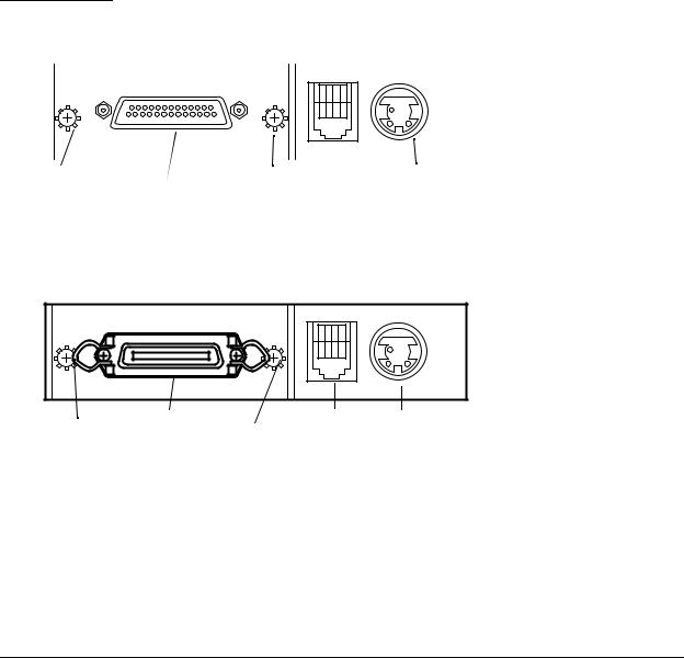
Frame ground screw |
Frame ground screw |
|
Power supply |
|||
|
Interface connector |
Drawer kick-out |
connector |
|||
|
connector |
|
|
|||
|
|
|
|
|
||
Figure 1-7 Connector panel (serial interface)
|
Interface connector |
Drawer kick-out |
Power suppl |
|
Frame ground |
Frame ground |
connector |
connector |
|
screw |
|
|||
|
screw |
|
|
|
|
|
|
|
|
Figure 1-8 Connector panel (parallel interface)
Interface Connector
See the interface section.
1-12 Features and General Specifications |
Rev.B |

CONFIDENTIAL
TM-U200D/U200PD Technical Manual
Power Supply Connector
This connector is used to connect the printer to an external power source.
Pin assignments: See the table below.
Model (printer side): Hosiden TCS7960-532010 (or equivalent)
Power supply connector pin assignments
Pin Number |
Signal Name |
|
|
1 |
+30V DC unregulated |
|
|
2 |
GND |
|
|
3 |
NC |
|
|
Shell |
Frame GND |
|
|
NOTE: Be sure to ground the frame ground (FG) screw on the board at the bottom of the unit. Ground wire terminal hole diameter: 3.2mm (.13"). Ground wire thickness: AWG 18 or equivalent.
Drawer Kick-Out Connector
A pulse specified by the ESC p command is output to the drawer kick-out connector. The host can confirm the status of the input signal by using the GS a, GS r, or DLE EOT commands.
Drawer kick-out connector pin assignments
Pin Number |
Signal name |
Direction |
|
|
|
1 |
Frame GND |
- |
|
|
|
2 |
Drawer kick-out drive signal 1(*2) |
Output |
|
|
|
3 |
Drawer open/close signal (*1) |
Input |
|
|
|
4 |
+24V DC |
- |
|
|
|
5 |
Drawer kick-out drive signal 2 (*2) |
Output |
|
|
|
6 |
Signal GND |
- |
|
|
|
(*1) Drawer open/close signal
The host computer can check the drawer open/close status with the DLE EOT, GS a, and GS r commands.
Input signal level: |
LOW = 0 V |
|
HIGH = 2 to 5V (at connector pin 3) |
Rev. B |
Features and General Specifications 1-13 |

CONFIDENTIAL
(*2) Drawer kick-out drive signal
Output signal: |
Voltage = Approximately 24V DC |
|
Current = 1 A or less |
Output waveform: |
Outputs the waveforms in Figure 1-8 to pins |
|
2 and 5 of the connector. t1 (ON time) and t2 |
|
(OFF time) are specified by ESC p. |
 CAUTION:
To avoid an overcurrent, the resistance of the drawer kick-out solenoid must be 24 Ω or more.
t1 x 2 ms t2 x 2 ms
Figure 1-9 Drawer kick-out drive signal output waveform
NOTES:
Two driver transistors cannot be energized simultaneously.
The drawer drive duty must be as shown below:
ON time
≤ 0.2
(ON time + OFF time)
Be sure to use the printer power supply (connector pin 4) for the drawer power source.
1-14 Features and General Specifications |
Rev.B |

CONFIDENTIAL
|
|
|
TM-U200D/U200PD Technical Manual |
|
|
|
|
Interface |
|
||
RS-232 Serial Interface |
|
||
|
Data transmission: |
Serial (compatible with RS-232) |
|
|
Synchronization: |
Asynchronous |
|
|
Handshaking: |
DTR/DSR or XON/XOFF control |
|
|
Signal levels: |
MARK = -3 to -15 V: Logic 1/OFF |
|
|
|
|
SPACE = +3 to +15 V: Logic 0/ON |
|
Baud rates: |
4800, 9600 bps |
|
|
Data word lengths: |
7 or 8 bits |
|
|
Parity settings: |
None, even, odd |
|
|
Stop bits: |
1 or more |
|
|
Connector: |
Female D-SUB 25-pin connector |
|
NOTES:
Handshaking, data word length, baud rate, and parity depend on DIP switch settings.
Data transmitted from the printer has 1 stop bit (fixed).
Rev. B |
Features and General Specifications 1-15 |

CONFIDENTIAL
Interface Connector Pin Assignments
TM-U200D printer status and signals
Pin number |
Signal name |
I/O |
|
|
|
Function |
|
|
|
|
|
|
|
|
|
|
|
|
|
1 |
FG |
- |
Frame ground |
|
|
|
|||
|
|
|
|
|
|
|
|
|
|
2 |
TXD |
O |
Transmit data |
|
|
|
|||
|
|
|
|
|
|
|
|
|
|
3 |
RXD |
I |
Receive data |
|
|
|
|||
|
|
|
|
|
|
|
|
|
|
4 |
RTS |
O |
Same as the DTR signal |
|
|
|
|||
|
|
|
|
|
|
|
|
|
|
6 |
DSR |
I |
This signal indicates whether the host computer can receive data. |
|
|
||||
|
|
|
SPACE indicates that the host computer can receive data, and MARK indicates |
||||||
|
|
|
that the host computer cannot receive data. |
|
|
|
|||
|
|
|
When DTR/DSR control is selected, the printer transmits data after confirming this |
||||||
|
|
|
signal (except when transmitting data by DLE EOT and GS a). |
|
|
|
|||
|
|
|
When XON/XOFF control is selected, the printer does not check this signal. |
||||||
|
|
|
Changing the DIP switch setting enables this signal to be used as a reset signal |
||||||
|
|
|
for the printer. |
|
|
|
|||
|
|
|
The printer is reset when the signal remains MARK for 1 ms or more. |
|
|
||||
|
|
|
|
|
|
|
|
|
|
7 |
SG |
- |
Signal ground |
|
|
|
|||
|
|
|
|
|
|
|
|
|
|
20 |
DTR |
O |
1) When DTR/DSR control is selected, this signal indicates whether the printer is |
||||||
|
|
|
busy. SPACE indicates that the printer is ready to receive data, and MARK |
||||||
|
|
|
indicates that the printer is busy. The busy condition can be changed by using |
||||||
|
|
|
DIP SW 1-8 as follows: |
|
|
|
|||
|
|
|
|
|
|
|
|
|
|
|
|
|
|
|
|
|
DIP SW 1-8 status |
|
|
|
|
|
|
Printer |
|
|
|
||
|
|
|
|
ON |
OFF |
|
|||
|
|
|
|
|
|
|
|
||
|
|
|
|
|
|
|
|
|
|
|
|
|
|
|
|
1. During the period from when the power is turned on |
|
|
|
|
|
|
|
|
|
(including resetting using the interface) to when the |
BUSY |
BUSY |
|
|
|
|
|
|
|
printer is ready to receive data. |
|
|
|
|
|
|
|
line- |
|
|
|
|
|
|
|
|
|
|
2. During the self-test |
BUSY |
BUSY |
|
|
|
|
|
|
|
|
|
|||
|
|
|
|
Off |
|
|
|
|
|
|
|
|
|
|
3. During paper feeding using the paper feed button. |
- |
BUSY |
|
|
|
|
|
|
|
|
|
|||
|
|
|
|
|
|
|
|
|
|
|
|
|
|
|
|
4. When the printer stops printing due to a paper-end. |
- |
BUSY |
|
|
|
|
|
|
|
|
|
|
|
|
|
|
|
|
|
5. When an error has occurred. |
- |
BUSY |
|
|
|
|
|
|
|
|
|
|
|
|
|
|
|
|
|
6. When a temporary abnormality occurs in the |
- |
BUSY |
|
|
|
|
|
|
|
power supply voltage |
|
||
|
|
|
|
|
|
|
|
|
|
|
|
|
|
|
|
|
|
|
|
|
|
|
|
|
|
7. When the receive buffer becomes full. (*1) |
BUSY |
BUSY |
|
|
|
|
|
|
|
|
|
|
|
|
|
|
|
|
|
|
|
|
|
20 |
DTR |
O |
2) When XON/XOFF control is selected: |
|
|
|
|||
|
|
|
This signal indicates whether the printer is correctly connected and is ready to |
||||||
|
|
|
receive data. SPACE indicates that the printer is ready to receive data. The |
||||||
|
|
|
signal is always SPACE except in the following cases: |
|
|
|
|||
|
|
|
During the period after the power is turned on until the printer is ready to |
||||||
|
|
|
|
receive data. |
|
|
|
||
|
|
|
During the self test. |
|
|
|
|||
|
|
|
|
|
|
|
|
|
|
25 |
INIT |
I |
Changing the DIP switch setting enables this signal to be used as a reset signal |
||||||
|
|
|
for the printer (see the DIP switch settings in the “Buttons and Switches” section |
||||||
|
|
|
of this chapter). The printer is reset when the signal remains SPACE for 1 ms or |
||||||
|
|
|
more. |
|
|
|
|
||
|
|
|
|
|
|
|
|
|
|
1-16 Features and General Specifications |
Rev.B |

CONFIDENTIAL
TM-U200D/U200PD Technical Manual
NOTES:
When the remaining space in the receive buffer is 16 bytes, the printer becomes buffer-full. This status continues until the space in the receive buffer increases to 32 bytes.
The printer ignores the data received when the remaining space in the receive buffer is 0 bytes.
On-line/Off-line switching
The printer does not have an on-line/off-line button. The printer goes off-line under the following conditions:
Between the time when the power is turned on (including reset using the interface) and when the printer is ready to receive data.
During the self-test.
During paper feeding using the PAPER FEED button.
Between the time when the printer stops printing due to a paper-end and when the on-line recovery wait time finishes after loading paper (in cases when empty paper supply is detected by either the paper roll end detector or the paper roll near-end detector with a printing halt feature set enabled due to paper shortage by ESC c 4).
When an error has occurred.
XON/XOFF transmit timing
When XON/XOFF control is selected, the printer transmits XON or XOFF signals as follows.
|
Printer status |
DIP SW 1-8 status |
||
|
|
|
||
|
ON |
OFF |
||
|
|
|||
|
|
|
|
|
|
• When the printer goes on line after turning on the power or |
Transmission |
Transmission |
|
XON |
reset using interface. |
Transmission |
Transmission |
|
• When the receive buffer is released from the buffer full state. |
---- |
Transmission |
||
transmission |
||||
• When the printer switches from off line to on line (*1). |
---- |
Transmission |
||
|
||||
|
• When the printer recovers from an error through a command. |
Transmission |
Transmission |
|
|
|
|
|
|
XOFF |
• During an error condition |
Transmission |
Transmission |
|
transmission |
• When the receive buffer becomes full (*2). |
---- |
Transmission |
|
|
|
|
|
|
(*1) XON is not transmitted when the receive buffer is full. (*2) XOFF is not transmitted when the receive buffer is full.
NOTE: The XON code is <11>H and the XOFF code is <13>H.
Rev. B |
Features and General Specifications 1-17 |

CONFIDENTIAL
Serial interface connection example
Host |
|
|
Printer |
||||
TXD |
|
|
|
RXD |
|||
|
|
|
|||||
DSR |
|
|
|
DTR |
|||
|
|
|
|||||
CTS |
|
|
|
|
RTS |
||
|
|
|
|
||||
RXD |
|
|
|
TXD |
|||
|
|
|
|||||
DTR |
|
|
|
DSR |
|||
|
|
|
|||||
FG |
|
|
|
|
FG |
||
|
|
|
|
||||
SG |
|
|
|
|
SG |
||
|
|
|
|
||||
NOTES:
Set the handshaking so that the transmit data can be received.
Transmit data to the printer after turning on the power and initializing the printer.
RS-485 Serial Interface (option)
Refer to the Appendix for details.
IEEE 1284 Parallel Interface
Copyright (C) 1994 by the Institute of electrical and Electronic Engineers, Inc.
Specification
Data transmission: |
8-bit parallel |
|
Synchronization: |
Externally supplied nStrobe signals |
|
Handshaking: |
nAck and Busy signals |
|
Signal levels: |
TTL compatible |
|
Connector: |
57RE-40360-830B (DDK) or equivalent (IEEE 1284 Type B) |
|
Reverse communication (Printer Host): |
Nibble or Byte Mode |
|
Reverse Mode (Data Transmission from Printer to Host)
The STATUS data transmission from the printer to the host is proceeded in the Nibble or Byte mode.
This mode allows data transmission from the asynchronous printer under the control of the host.
Data transmissions in the Nibble Mode are made via the existing control lines in unists of four bits (Nibble). In the Byte Mode, data transmissions are proceeded by making the eight-bit data lines bidirectional.
1-18 Features and General Specifications |
Rev.B |

CONFIDENTIAL
TM-U200D/U200PD Technical Manual
The both modes fail to be proceeded concurrently with the Compatibility Mode, thereby causing half duplex transmission.
The IEEE 1284 Nibble/Byte Modes are under development in the form of draft and may be subject to change.
Rev. B |
Features and General Specifications 1-19 |
Loading...