


TM-T88II/T88III
Technical reference guide
English
405227700
EPSON

TM-T88II/T88III Technical Reference Guide
Cautions
No part of this document may be reproduced, stored in a retrieval system, or transmitted in any form or by any means, electronic, mechanical, photocopying, recabling, or otherwise, without the prior written permission of Seiko Epson Corporation.
The contents of this document are subject to change without notice. Please contact us for the latest information.
While every precaution has been taken in the preparation of this document, Seiko Epson Corporation assumes no responsibility for errors or omissions.
Neither is any liability assumed for damages resulting from the use of the information contained herein.
Neither Seiko Epson Corporation nor its affiliates shall be liable to the purchaser of this product or third parties for damages, losses, costs, or expenses incurred by the purchaser or third parties as a result of: accident, misuse, or abuse of this product or unauthorized modifications, repairs, or alterations to this product, or (excluding the U.S.) failure to strictly comply with Seiko Epson Corporation’s operating and maintenance instructions.
Seiko Epson Corporation shall not be liable against any damages or problems arising from the use of any options or any consumable products other than those designated as Original EPSON Products or EPSON Approved Products by Seiko Epson Corporation.
Trademarks
EPSON and ESC/POS are registered trademarks of Seiko Epson Corporation.
ESC/POS“ Command System
EPSON has been taking industry's initiatives with its own POS printer command system (ESC/POS). ESC/POS has a large number of commands including patented ones. Its high scalability enables users to build versatile POS systems. The system is compatible with all types of EPSON POS printers and displays. Moreover, its flexibility make it easy to upgrade in the future. The functionality and the user-friendliness is valued from around the world.
Revision History
Rev. |
Page |
Details of Change |
|
|
|
Rev. A |
All pages |
Newly authorized |
|
|
|
Rev. A |
i |

For Safety
Key to Symbols
The symbols in this manual are identified by their level of importance, as defined below. Read the following carefully before handling the product.
 WARNING:
You must follow warnings carefully to avoid serious bodily injury.
 CAUTION:
Provides information that must be observed to prevent damage to the equipment or loss of data.
Possibility of sustaining physical injuries.
Possibility of causing physical damages.
Possibility of causing information loss.
 Note:
Note:
Provides important information and useful tips on handling the equipment.
ii |
Rev. A |

TM-T88II/T88III Technical Reference Guide
Warnings
 WARNING:
Shut down your equipment immediately if it produces smoke, a strange odor, or unusual noise. Continued use may lead to fire or electric shock. Immediately unplug the equipment.
Only disassemble this product as described in this manual. Do not make modifications to the unit. Tampering with this product may result in injury, fire, or electric shock.
To avoid risk of electric shock, do not set up this product or handle cables during a thunderstorm in order.
Be sure to use the specified power source. Connection to an improper power source may cause fire or shock.
Never insert or disconnect the power plug with wet hands. Doing so may result in severe shock.
Do not allow foreign matter to fall into the equipment. Penetration by foreign objects may lead to fire or electric shock.
If water or other liquid spills into this equipment, turn off the power supply switch and unplug the power cable immediately. Continued usage may lead to fire or electric shock.
Do not place multiple loads on power outlet. Overloading the outlet may lead to fire. Always supply power directly from a standard 100 VAC domestic power outlet.
Handle the power cable with care. Improper handling may lead to fire or electric shock.
•Do not modify or attempt to repair the cable.
•Do not place any heavy object on top of the cable.
•Avoid excessive bending, twisting and pulling.
•Do not place the cable near heating equipment.
•Check that the plug is clean before plugging it in.
•Be sure to push the plug all the way in.
Cautions
 CAUTION:
Be sure to set this equipment on a firm, stable horizontal surface. Product may break or cause injury if it falls.
Do not use in locations subject to high humidity or dust levels. Excessive humidity and dust may cause equipment damage, fire or shock.
Rev. A |
iii |

Do not place heavy objects on top of this equipment. Never stand or lean on this equipment. Equipment may fall or collapse, causing breakage and possible injury.
To ensure safety, unplug this equipment prior to leaving it unused for an extended period.
Parts on the circuit board may become hot during operation. Wait approximately 10 minutes after turning the power off before touching them.
To avoid injury, take care not to insert fingers or any part of the hand in the roll paper opening where the manual cutter is installed.
Do not open the roll paper cover without taking the necessary precautions, as this can result in injury from the autocutter fixed blade.
A needle for supplying ink to the printer is located inside the ink cartridge holder. Inserting your fingers inside the ink cartridge holder may cause an injury.
Modular Connectors
The printer uses the modular connectors specifically designed for the cash drawer or customer display. Do not connect these connectors to an ordinary telephone line.
iv |
Rev. A |

TM-T88II/T88III Technical Reference Guide
About this Manual
This manual describes the TM-T88III, a current EPSON thermal printer product.
This manual also describes the TM-T88II, an obsolete product, for the purpose of supporting legacy systems. The TM-T88II has been replaced by the newer TM-T88III. However, even though the TM-T88II is no longer being sold, it is still in use by customers.
In addition, the power supply that was originally available for the TM-T88II printer, the PS-170, is obsolete and no longer available. It is described only for legacy support. The currently available power supply, the PS-180, works with either printer model.
Aim of the Manual
This manual was created to provide all the information necessary for system planning, design, installation, and application of the printer for designers and developers of POS system.
Manual Content
The manual is made up of the following sections:
Chapter 1 |
Product Overview |
Chapter 2 |
Setup |
Chapter 3 |
Application Development Information |
Chapter 4 |
ESC/POS Command-related Information |
Chapter 5 |
Product Specifications |
Appendix A |
Interfaces and Connectors |
Appendix B |
Options and Consumables |
Appendix C |
Character Code Tables |
Appendix D |
TM-T88II/TM-88III Comparison Table |
Related Software and Documents
Documents relating to the TM-T88II/TM-T88III are listed below.
Name of document |
Description |
|
|
TM-T88II User’s Manual |
Provides information to enable POS operators to use the |
TM-T88III User’s Manual |
TM-T88II/TM-T88III safely and correctly. This manual is packed in |
|
the box with the printer.* |
|
|
ESC/POS Application Programming Guide |
Provides detailed ESC/POS command information. Contact us |
|
to obtain this guide. |
|
|
TM-T88II/T88III Technical Reference Guide |
This guide.* |
|
|
EPSON OPOS ADK |
This is an OCX driver.* |
|
|
Rev. A |
v |

Name of document |
Description |
|
|
EPSON OPOS ADK Manual |
Provides information for anyone who is programming using |
|
OPOS. This is included in the EPSON OPOS ADK.* |
|
|
EPSON Advanced Printer Driver |
This is a Windows driver.* |
|
|
EPSON Advanced Printer Driver Manual |
Provides information for anyone who is programming using |
|
the APD (EPSON Advanced Printer Driver). This is included in |
|
the EPSON Advanced Printer Driver.* |
|
|
* You can obtain these items from one of the following URLs: For customers from North America: http://pos.epson.com/
For customers from other countries: http://epson-pos.com/
Select the product from the “Select any product” pull-down menu.
vi |
Rev. A |

TM-T88II/T88III Technical Reference Guide
Contents
Revision History . . . . . . . . . . . . . . . . . . . . . . . . . . . . . . . . . . . . . . . . . . . . . . . . . . . . . . . . . . . . . . . . . . . . . . . . . . . . . . i For Safety . . . . . . . . . . . . . . . . . . . . . . . . . . . . . . . . . . . . . . . . . . . . . . . . . . . . . . . . . . . . . . . . . . . . . . . . . . . . . . . . . . . . ii Key to Symbols . . . . . . . . . . . . . . . . . . . . . . . . . . . . . . . . . . . . . . . . . . . . . . . . . . . . . . . . . . . . . . . . . . . . . . . . . . . ii Warnings . . . . . . . . . . . . . . . . . . . . . . . . . . . . . . . . . . . . . . . . . . . . . . . . . . . . . . . . . . . . . . . . . . . . . . . . . . . . . . . . . iii Cautions . . . . . . . . . . . . . . . . . . . . . . . . . . . . . . . . . . . . . . . . . . . . . . . . . . . . . . . . . . . . . . . . . . . . . . . . . . . . . . . . . iii Modular Connectors . . . . . . . . . . . . . . . . . . . . . . . . . . . . . . . . . . . . . . . . . . . . . . . . . . . . . . . . . . . . . . . . . . . . . . . . . . . iv About this Manual . . . . . . . . . . . . . . . . . . . . . . . . . . . . . . . . . . . . . . . . . . . . . . . . . . . . . . . . . . . . . . . . . . . . . . . . . . . . . v Aim of the Manual . . . . . . . . . . . . . . . . . . . . . . . . . . . . . . . . . . . . . . . . . . . . . . . . . . . . . . . . . . . . . . . . . . . . . . . . . v Manual Content . . . . . . . . . . . . . . . . . . . . . . . . . . . . . . . . . . . . . . . . . . . . . . . . . . . . . . . . . . . . . . . . . . . . . . . . . . . v Related Software and Documents . . . . . . . . . . . . . . . . . . . . . . . . . . . . . . . . . . . . . . . . . . . . . . . . . . . . . . . . . . . . v
Chapter 1 Product Overview
Product Structure . . . . . . . . . . . . . . . . . . . . . . . . . . . . . . . . . . . . . . . . . . . . . . . . . . . . . . . . . . . . . . . . . . . . . . . . . . . . . . 1-1 Model . . . . . . . . . . . . . . . . . . . . . . . . . . . . . . . . . . . . . . . . . . . . . . . . . . . . . . . . . . . . . . . . . . . . . . . . . . . . . . . . . . . . 1-1 Accessories . . . . . . . . . . . . . . . . . . . . . . . . . . . . . . . . . . . . . . . . . . . . . . . . . . . . . . . . . . . . . . . . . . . . . . . . . . . . . . . 1-1 Options . . . . . . . . . . . . . . . . . . . . . . . . . . . . . . . . . . . . . . . . . . . . . . . . . . . . . . . . . . . . . . . . . . . . . . . . . . . . . . . . . . 1-1 Consumable products . . . . . . . . . . . . . . . . . . . . . . . . . . . . . . . . . . . . . . . . . . . . . . . . . . . . . . . . . . . . . . . . . . . . . . 1-1 TM-T88II/TM-88III Comparison Table . . . . . . . . . . . . . . . . . . . . . . . . . . . . . . . . . . . . . . . . . . . . . . . . . . . . . . . 1-2
Part Names and Basic Operation . . . . . . . . . . . . . . . . . . . . . . . . . . . . . . . . . . . . . . . . . . . . . . . . . . . . . . . . . . . . . . . . 1-3 Part Names . . . . . . . . . . . . . . . . . . . . . . . . . . . . . . . . . . . . . . . . . . . . . . . . . . . . . . . . . . . . . . . . . . . . . . . . . . . . . . . 1-3 Control Panel . . . . . . . . . . . . . . . . . . . . . . . . . . . . . . . . . . . . . . . . . . . . . . . . . . . . . . . . . . . . . . . . . . . . . . . . . . . . . 1-3 Power Switch . . . . . . . . . . . . . . . . . . . . . . . . . . . . . . . . . . . . . . . . . . . . . . . . . . . . . . . . . . . . . . . . . . . . . . . . . . . . . 1-4 Connectors . . . . . . . . . . . . . . . . . . . . . . . . . . . . . . . . . . . . . . . . . . . . . . . . . . . . . . . . . . . . . . . . . . . . . . . . . . . . . . . 1-5
Handling the Printer . . . . . . . . . . . . . . . . . . . . . . . . . . . . . . . . . . . . . . . . . . . . . . . . . . . . . . . . . . . . . . . . . . . . . . . . . . . 1-5 Installing and Replacing Roll Paper . . . . . . . . . . . . . . . . . . . . . . . . . . . . . . . . . . . . . . . . . . . . . . . . . . . . . . . . . . 1-6 Power Switch Cover . . . . . . . . . . . . . . . . . . . . . . . . . . . . . . . . . . . . . . . . . . . . . . . . . . . . . . . . . . . . . . . . . . . . . . . 1-7 Shipping Procedures . . . . . . . . . . . . . . . . . . . . . . . . . . . . . . . . . . . . . . . . . . . . . . . . . . . . . . . . . . . . . . . . . . . . . . . 1-8
Chapter 2 Setup |
|
Installing the Printer . . . . . . . . . . . . . . . . . . . . . . . . . . . . . . . . . . . . . . . . . . . . . . . . . . . . . . . . . . . . . . . . . . . . . . . . . . . |
2-2 |
Precautions for Horizontal Installation . . . . . . . . . . . . . . . . . . . . . . . . . . . . . . . . . . . . . . . . . . . . . . . . . . . . . . . |
2-2 |
Precautions for Wall Installation . . . . . . . . . . . . . . . . . . . . . . . . . . . . . . . . . . . . . . . . . . . . . . . . . . . . . . . . . . . . . |
2-2 |
Setting the DIP Switches . . . . . . . . . . . . . . . . . . . . . . . . . . . . . . . . . . . . . . . . . . . . . . . . . . . . . . . . . . . . . . . . . . . . . . . . |
2-2 |
DIP Switch Positions and Steps for Changing DIP Switch Settings . . . . . . . . . . . . . . . . . . . . . . . . . . . . . . . |
2-2 |
DIP Switch Functions . . . . . . . . . . . . . . . . . . . . . . . . . . . . . . . . . . . . . . . . . . . . . . . . . . . . . . . . . . . . . . . . . . . . . . |
2-3 |
Adjusting the Roll Paper Near-End Detector . . . . . . . . . . . . . . . . . . . . . . . . . . . . . . . . . . . . . . . . . . . . . . . . . . . . . . |
2-7 |
Connecting the Printer to the Host Computer . . . . . . . . . . . . . . . . . . . . . . . . . . . . . . . . . . . . . . . . . . . . . . . . . . . . . |
2-8 |
Serial Interface Connection . . . . . . . . . . . . . . . . . . . . . . . . . . . . . . . . . . . . . . . . . . . . . . . . . . . . . . . . . . . . . . . . . |
2-8 |
Parallel Interface Connection . . . . . . . . . . . . . . . . . . . . . . . . . . . . . . . . . . . . . . . . . . . . . . . . . . . . . . . . . . . . . . . . |
2-11 |
USB Interface Connection . . . . . . . . . . . . . . . . . . . . . . . . . . . . . . . . . . . . . . . . . . . . . . . . . . . . . . . . . . . . . . . . . . . |
2-11 |
Ethernet Interface Connection . . . . . . . . . . . . . . . . . . . . . . . . . . . . . . . . . . . . . . . . . . . . . . . . . . . . . . . . . . . . . . . |
2-13 |
Connecting Power Supply Unit and Cash Drawer . . . . . . . . . . . . . . . . . . . . . . . . . . . . . . . . . . . . . . . . . . . . . . . . . . |
2-15 |
Connecting the Power Supply Unit . . . . . . . . . . . . . . . . . . . . . . . . . . . . . . . . . . . . . . . . . . . . . . . . . . . . . . . . . . |
2-15 |
Connecting the Drawer Kick-out Cable . . . . . . . . . . . . . . . . . . . . . . . . . . . . . . . . . . . . . . . . . . . . . . . . . . . . . . . |
2-16 |
Installing the Driver . . . . . . . . . . . . . . . . . . . . . . . . . . . . . . . . . . . . . . . . . . . . . . . . . . . . . . . . . . . . . . . . . . . . . . . . . . . |
2-16 |
Chapter 3 Application Development Information
Introducing the Control Methods . . . . . . . . . . . . . . . . . . . . . . . . . . . . . . . . . . . . . . . . . . . . . . . . . . . . . . . . . . . . . . . . 3-1
Windows Driver (EPSON Advanced Printer Driver) . . . . . . . . . . . . . . . . . . . . . . . . . . . . . . . . . . . . . . . . . . . 3-1
EPSON OPOS ADK . . . . . . . . . . . . . . . . . . . . . . . . . . . . . . . . . . . . . . . . . . . . . . . . . . . . . . . . . . . . . . . . . . . . . . . . 3-3
Contents vii

ESC/POS Commands . . . . . . . . . . . . . . . . . . . . . . . . . . . . . . . . . . . . . . . . . . . . . . . . . . . . . . . . . . . . . . . . . . . . . . |
3-5 |
Various Utilities . . . . . . . . . . . . . . . . . . . . . . . . . . . . . . . . . . . . . . . . . . . . . . . . . . . . . . . . . . . . . . . . . . . . . . . . . . . |
3-6 |
Switches and Buttons . . . . . . . . . . . . . . . . . . . . . . . . . . . . . . . . . . . . . . . . . . . . . . . . . . . . . . . . . . . . . . . . . . . . . . . . . . . |
3-6 |
Paper FEED Button . . . . . . . . . . . . . . . . . . . . . . . . . . . . . . . . . . . . . . . . . . . . . . . . . . . . . . . . . . . . . . . . . . . . . . . . |
3-6 |
Panel LEDs and Error Status . . . . . . . . . . . . . . . . . . . . . . . . . . . . . . . . . . . . . . . . . . . . . . . . . . . . . . . . . . . . . . . . . . . . |
3-7 |
Power LED . . . . . . . . . . . . . . . . . . . . . . . . . . . . . . . . . . . . . . . . . . . . . . . . . . . . . . . . . . . . . . . . . . . . . . . . . . . . . . . |
3-7 |
No Roll Paper (PAPER OUT) LED . . . . . . . . . . . . . . . . . . . . . . . . . . . . . . . . . . . . . . . . . . . . . . . . . . . . . . . . . . . |
3-7 |
Error LED . . . . . . . . . . . . . . . . . . . . . . . . . . . . . . . . . . . . . . . . . . . . . . . . . . . . . . . . . . . . . . . . . . . . . . . . . . . . . . . . |
3-7 |
Sensors . . . . . . . . . . . . . . . . . . . . . . . . . . . . . . . . . . . . . . . . . . . . . . . . . . . . . . . . . . . . . . . . . . . . . . . . . . . . . . . . . . . . . . . |
3-10 |
Paper Sensors . . . . . . . . . . . . . . . . . . . . . . . . . . . . . . . . . . . . . . . . . . . . . . . . . . . . . . . . . . . . . . . . . . . . . . . . . . . . . |
3-10 |
Printer Cover Sensor . . . . . . . . . . . . . . . . . . . . . . . . . . . . . . . . . . . . . . . . . . . . . . . . . . . . . . . . . . . . . . . . . . . . . . . |
3-10 |
Offline . . . . . . . . . . . . . . . . . . . . . . . . . . . . . . . . . . . . . . . . . . . . . . . . . . . . . . . . . . . . . . . . . . . . . . . . . . . . . . . . . . . |
3-11 |
Busy State . . . . . . . . . . . . . . . . . . . . . . . . . . . . . . . . . . . . . . . . . . . . . . . . . . . . . . . . . . . . . . . . . . . . . . . . . . . . . . . . |
3-11 |
NVRAM (Non-volatile Memory) . . . . . . . . . . . . . . . . . . . . . . . . . . . . . . . . . . . . . . . . . . . . . . . . . . . . . . . . . . . . . . . . . |
3-12 |
Bar Code Printing . . . . . . . . . . . . . . . . . . . . . . . . . . . . . . . . . . . . . . . . . . . . . . . . . . . . . . . . . . . . . . . . . . . . . . . . . . . . . . |
3-12 |
Operating Mode (Switch Panel Operation) . . . . . . . . . . . . . . . . . . . . . . . . . . . . . . . . . . . . . . . . . . . . . . . . . . . . . . . . |
3-13 |
Self-test Mode . . . . . . . . . . . . . . . . . . . . . . . . . . . . . . . . . . . . . . . . . . . . . . . . . . . . . . . . . . . . . . . . . . . . . . . . . . . . . |
3-13 |
FAQ List . . . . . . . . . . . . . . . . . . . . . . . . . . . . . . . . . . . . . . . . . . . . . . . . . . . . . . . . . . . . . . . . . . . . . . . . . . . . . . . . . . . . . . |
3-14 |
Q: Why has my print data dropped out? . . . . . . . . . . . . . . . . . . . . . . . . . . . . . . . . . . . . . . . . . . . . . . . . . . . . . . |
3-14 |
Q: Why does the drawer kick-out not operate properly? . . . . . . . . . . . . . . . . . . . . . . . . . . . . . . . . . . . . . . . . |
3-15 |
Q: I cannot print part of Page 0 in Visual Basic. Why? . . . . . . . . . . . . . . . . . . . . . . . . . . . . . . . . . . . . . . . . . . . |
3-15 |
Chapter 4 ESC/POS Command-related Information
NV Memory (Non-volatile Memory) . . . . . . . . . . . . . . . . . . . . . . . . . . . . . . . . . . . . . . . . . . . . . . . . . . . . . . . . . . . . . 4-1
Using NV Memory . . . . . . . . . . . . . . . . . . . . . . . . . . . . . . . . . . . . . . . . . . . . . . . . . . . . . . . . . . . . . . . . . . . . . . . . . 4-1
Printer Status . . . . . . . . . . . . . . . . . . . . . . . . . . . . . . . . . . . . . . . . . . . . . . . . . . . . . . . . . . . . . . . . . . . . . . . . . . . . . . . . . . 4-2
Precautions When the Printer Is Offline . . . . . . . . . . . . . . . . . . . . . . . . . . . . . . . . . . . . . . . . . . . . . . . . . . . . . . . . . . . 4-2
Outputting Hex Dumps . . . . . . . . . . . . . . . . . . . . . . . . . . . . . . . . . . . . . . . . . . . . . . . . . . . . . . . . . . . . . . . . . . . . . . . . 4-2
Chapter 5 Product Specifications
Product Specifications (TM-T88II/TM-T88III) . . . . . . . . . . . . . . . . . . . . . . . . . . . . . . . . . . . . . . . . . . . . . . . . . . . . . . 5-1 Print Specifications (TM-T88II/TM-T88III) . . . . . . . . . . . . . . . . . . . . . . . . . . . . . . . . . . . . . . . . . . . . . . . . . . . . . . . . 5-2 Character Specifications (TM-T88II/TM-T88III) . . . . . . . . . . . . . . . . . . . . . . . . . . . . . . . . . . . . . . . . . . . . . . . . . . . 5-3 Paper Specifications (TM-T88II/TM-T88III) . . . . . . . . . . . . . . . . . . . . . . . . . . . . . . . . . . . . . . . . . . . . . . . . . . . . . . . 5-3 Printable Area (TM-T88II/TM-T88III) . . . . . . . . . . . . . . . . . . . . . . . . . . . . . . . . . . . . . . . . . . . . . . . . . . . . . . . . . . . . 5-4 Print Position versus Cutter Position (TM-88II/TM88III) . . . . . . . . . . . . . . . . . . . . . . . . . . . . . . . . . . . . . . . . . . . . 5-5 Overview of External Dimensions (TM-T88II/TM-T88III) . . . . . . . . . . . . . . . . . . . . . . . . . . . . . . . . . . . . . . . . . . . 5-6
External Dimensions . . . . . . . . . . . . . . . . . . . . . . . . . . . . . . . . . . . . . . . . . . . . . . . . . . . . . . . . . . . . . . . . . . . . . . . 5-6 Operating Specifications (TM-T88II/TM-T88III) . . . . . . . . . . . . . . . . . . . . . . . . . . . . . . . . . . . . . . . . . . . . . . . . . . . . 5-7
Appendix A Interfaces and Connectors
RS-232 Serial Interface . . . . . . . . . . . . . . . . . . . . . . . . . . . . . . . . . . . . . . . . . . . . . . . . . . . . . . . . . . . . . . . . . . . . . . . . . . A-1 Interface Board Specifications (RS-232-compliant) . . . . . . . . . . . . . . . . . . . . . . . . . . . . . . . . . . . . . . . . . . . . . . A-1 Functions of each Connector Pin . . . . . . . . . . . . . . . . . . . . . . . . . . . . . . . . . . . . . . . . . . . . . . . . . . . . . . . . . . . . . A-2 XON/XOFF . . . . . . . . . . . . . . . . . . . . . . . . . . . . . . . . . . . . . . . . . . . . . . . . . . . . . . . . . . . . . . . . . . . . . . . . . . . . . . . A-2 Code . . . . . . . . . . . . . . . . . . . . . . . . . . . . . . . . . . . . . . . . . . . . . . . . . . . . . . . . . . . . . . . . . . . . . . . . . . . . . . . . . . . . . A-3
IEEE 1284 Parallel Interface . . . . . . . . . . . . . . . . . . . . . . . . . . . . . . . . . . . . . . . . . . . . . . . . . . . . . . . . . . . . . . . . . . . . . A-3 Modes . . . . . . . . . . . . . . . . . . . . . . . . . . . . . . . . . . . . . . . . . . . . . . . . . . . . . . . . . . . . . . . . . . . . . . . . . . . . . . . . . . . . A-3 Interface Signals . . . . . . . . . . . . . . . . . . . . . . . . . . . . . . . . . . . . . . . . . . . . . . . . . . . . . . . . . . . . . . . . . . . . . . . . . . . A-5
Appendix B Options and Consumables
Roll Paper . . . . . . . . . . . . . . . . . . . . . . . . . . . . . . . . . . . . . . . . . . . . . . . . . . . . . . . . . . . . . . . . . . . . . . . . . . . . . . . . . . . . B-1
Power Supply . . . . . . . . . . . . . . . . . . . . . . . . . . . . . . . . . . . . . . . . . . . . . . . . . . . . . . . . . . . . . . . . . . . . . . . . . . . . . . . . . B-1
PS-170 . . . . . . . . . . . . . . . . . . . . . . . . . . . . . . . . . . . . . . . . . . . . . . . . . . . . . . . . . . . . . . . . . . . . . . . . . . . . . . . . . . . . B-1
PS-180 . . . . . . . . . . . . . . . . . . . . . . . . . . . . . . . . . . . . . . . . . . . . . . . . . . . . . . . . . . . . . . . . . . . . . . . . . . . . . . . . . . . . B-2
viii Contents |
Rev. A |
TM-T88II/T88III Technical Reference Guide
Appendix C Character Code Tables
Page 0 (PC437: USA, Standard Europe) . . . . . . . . . . . . . . . . . . . . . . . . . . . . . . . . . . . . . . . . . . . . . . . . . . . . . . . . . . . C-1 Page 1 (Katakana) . . . . . . . . . . . . . . . . . . . . . . . . . . . . . . . . . . . . . . . . . . . . . . . . . . . . . . . . . . . . . . . . . . . . . . . . . . . . . C-2 Page 2 (PC850: Multilingual) . . . . . . . . . . . . . . . . . . . . . . . . . . . . . . . . . . . . . . . . . . . . . . . . . . . . . . . . . . . . . . . . . . . . C-3 Page 3 (PC860: Portuguese) . . . . . . . . . . . . . . . . . . . . . . . . . . . . . . . . . . . . . . . . . . . . . . . . . . . . . . . . . . . . . . . . . . . . . C-4 Page 4 (PC863: Canadian-French) . . . . . . . . . . . . . . . . . . . . . . . . . . . . . . . . . . . . . . . . . . . . . . . . . . . . . . . . . . . . . . . . C-5 Page 5 (PC865: Nordic) . . . . . . . . . . . . . . . . . . . . . . . . . . . . . . . . . . . . . . . . . . . . . . . . . . . . . . . . . . . . . . . . . . . . . . . . . C-6 Page 16 (WPC1252) (TM-T88III only) . . . . . . . . . . . . . . . . . . . . . . . . . . . . . . . . . . . . . . . . . . . . . . . . . . . . . . . . . . . . . C-7 Page 17 (PC866: Cyrillic #2) (TM-T88III only) . . . . . . . . . . . . . . . . . . . . . . . . . . . . . . . . . . . . . . . . . . . . . . . . . . . . . . C-8 Page 18 (PC852: Latin2) (TM-T88III only) . . . . . . . . . . . . . . . . . . . . . . . . . . . . . . . . . . . . . . . . . . . . . . . . . . . . . . . . . C-9 Page 19 (PC858: Euro) . . . . . . . . . . . . . . . . . . . . . . . . . . . . . . . . . . . . . . . . . . . . . . . . . . . . . . . . . . . . . . . . . . . . . . . . . . C-10 Page 255 (Blank Page) . . . . . . . . . . . . . . . . . . . . . . . . . . . . . . . . . . . . . . . . . . . . . . . . . . . . . . . . . . . . . . . . . . . . . . . . . . C-11 International Character Set . . . . . . . . . . . . . . . . . . . . . . . . . . . . . . . . . . . . . . . . . . . . . . . . . . . . . . . . . . . . . . . . . . . . . . C-12
Appendix D TM-T88II/TM-88III Comparison Table
Contents ix

x Contents |
Rev. A |

TM-T88II/T88III Technical Reference Guide
Chapter 1
Product Overview
The TM-T88III thermal printer product is currently available from EPSON. The TM-T88II is an obsolete product, which is described here for the purpose of supporting legacy systems.
In addition, the PS-170, the power supply for the TM-T88II printer, also is obsolete and no longer available. It is described only for legacy support. The currently available power supply, the PS-180, works with either printer model.
1.1 Product Structure
1.1.1 Model
Product Name |
TM-T88III (current product)/TM-T88II (legacy product) |
• Print method: |
Thermal line printing |
•Interface specifications:
Serial interface specifications (RS-232C)
Parallel interface specifications (IEEE 1284-compliant) USB interface specifications
Ethernet interface specifications
•Paper width specifications:
80 mm {3.15"} width specifications
58 mm {2.28"} width specifications
1.1.2Accessories
Printer (body)
Roll paper (outer diameter 50 mm {2"}) × 1
User’s manual × 1
Power switch cover × 1
External power supply unit model: PS-180 (TM-T88III: packaged power supply)
Power cable model: AC-170 for PS-170. (The PS-170 and TM-T88II are no longer being sold.)
1.1.3Options
External power supply unit
•Model PS-170 (This option has been replaced by the PS-180, which works for both printers.)
•Model PS-180 (*1) (PS-180 supports the power-saving feature.)
Rev. A |
Product Overview 1-1 |

Power cable (model: AC-170) (*1)
(*1) The power supply unit and power cable may not come packaged with the TM-T88III. Purchase these separately, if necessary. (The PS-170 power supply has been replaced by the PS-180 and is no longer being sold.)
1.1.4Consumable products
Specified paper: Thermal paper
1.1.5TM-T88II/TM-88III Comparison Table
Table 1-1 Differences between the TM-T88II and TM-T88III
|
TM-T88III (current model) |
TM-T88II (legacy model) |
|
|
|
1. High-speed print mode |
Approx. 150 mm/s (4.72") maximum |
Approx. 120 mm/s (4.72") maximum |
|
|
|
2. High-speed power |
Average approx. 1.8 A |
Average approx. 1.7 A |
consumption mode |
|
|
|
|
|
3. Serial interface selectable |
4800, 9600, 19200, 38400, |
2400, 4800, 9600, 19200 |
baud rates |
(2400 discontinued, 38400 added). |
|
|
38400 is selected by setting DIP SW1-7 |
|
|
and 1-8 to ON. (See “DIP Switch |
|
|
Functions” (page 2-3).) |
|
|
|
|
4. Conditions for canceling |
Set with DIP SW2-5 * |
Cannot be changed. |
receive buffer BUSY state * |
|
|
|
|
|
5. Supported character sets |
11 pages including WPC 1252, |
8 pages |
(extended graphics) |
PC866 [Cyrillic #2], PC852 [Latin2]) |
|
|
|
|
6. Driver (EPSON OPOS ADK, |
Also can be operated by the driver for |
— |
Advanced Printer Driver) |
the TM-T88II. Functions, however, are |
|
|
restricted as follows: |
|
|
• Some baud rates cannot be used in |
|
|
serial communications (38400 bps, |
|
|
2400 bps). |
|
|
Note: The driver cannot set a |
|
|
38400 bps baud rate. Selecting |
|
|
a 2400 bps baud rate with the |
|
|
driver will cause garbled |
|
|
characters (the printer does not |
|
|
support a 2400 bps baud rate). |
|
|
|
|
* For details on the conditions for canceling the receive buffer BUSY state, refer to “DIP Switch Functions” (page 2-3).
1-2 Product Overview |
Rev. A |
TM-T88II/T88III Technical Reference Guide
1.2 Part Names and Basic Operation
1.2.1 Part Names
|
|
|
POWER |
O |
PA |
P |
ERROR |
UT |
ER |
||
FEED |
|
|
|
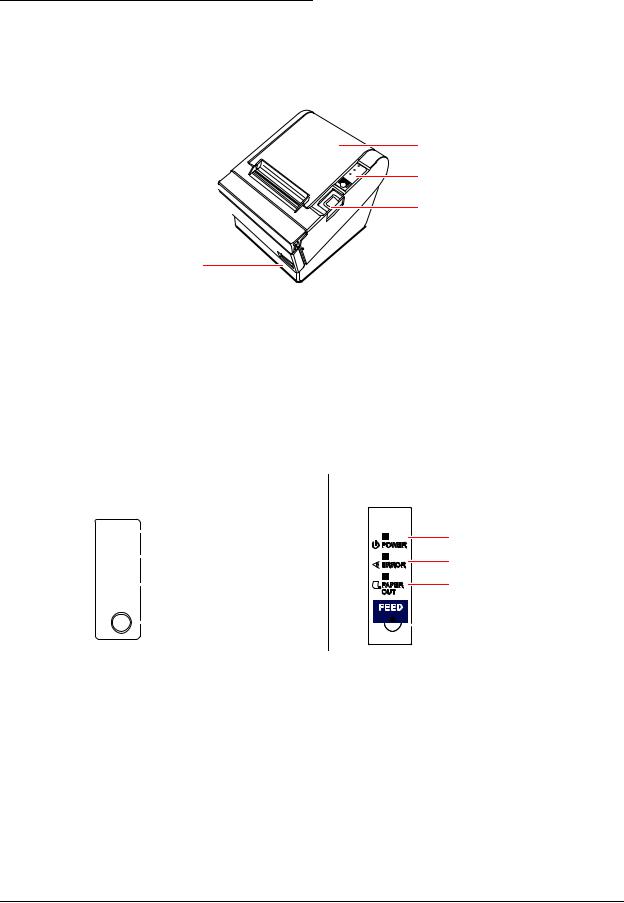
Cutter cover 
Power switch
Printer cover
Control panel
Cover open button
Figure 1-1 Printer part names
* For details on DIP switch settings, refer to “DIP Switch Positions and Steps for Changing DIP Switch Settings” (page 2-2).
1.2.2 Control Panel
TM-T88II |
TM-T88III |
|
|
|
|
POWER LED |
|
POWER |
|
||||
|
|
||||
|
|
ERROR LED |
|||
|
|
|
|
||
ERROR |
|||||
|
|||||
|
|
|
|||
|
|
|
|
|
|
PAPER |
|
PAPER OUT LED |
|||
|
|||||
OUT |
|
|
|||
FEED |
|
|
|||
|
|
|
|
FEED button |
|
|
|
|
|
||
POWER LED |
ERROR LED |
PAPER OUT LED |

 FEED button
Figure 1-2 Control panels for the TM-T88II (legacy model) and TM-T88III (current model)
Rev. A |
Product Overview 1-3 |

1.2.2.1 LED
POWER LED (green)
Lights when the power supply is on.
Goes out when the power supply is turned off.
ERROR LED
Lights or flashes when the printer is offline.
Lights after the power is turned on or after a reset (offline). Automatically goes out after a while to indicate that the printer is ready.
Lights when the end of the roll paper is detected, and when printing has stopped (offline). If this happens, replace with new roll paper.
Flashes when an error occurs. (For details about the flash codes, refer to “Error Codes” (page 3-8).)
Goes out during regular operation (online).
PAPER OUT LED
Lights when there is no more roll paper or there is little remaining.
Goes out when there is a sufficient amount of roll paper remaining.
Flashes when a self-test is in progress or when the printer waits for a macro execution.
1.2.2.2 Buttons
PAPER FEED button
Pressing this button once feeds the roll paper by one line. Holding this button down feeds the roll paper continuously.
1.2.3 Power Switch
The power switch is located at the bottom right front of the printer. (Refer to “Printer part names” (page 1-3).)
Turn the printer on or off. The marks on the switch (0 = on / 1 = off) indicate the printer switch position.
 CAUTION:
Before turning on the printer be sure to check that the AC adapter is connected to the power supply.
1-4 Product Overview |
Rev. A |
TM-T88II/T88III Technical Reference Guide
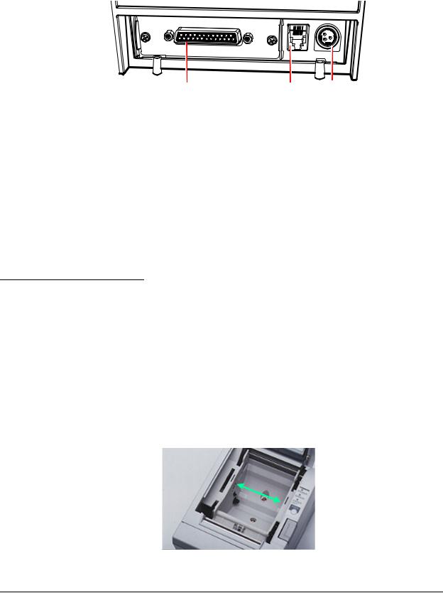
1.2.4 Connectors
All cables are connected to the connector panel on the lower rear of the printer.
FG |
FG |
|
DK
DC24V
Interface connector |
Drawer kick-out connector |
Power supply connector |
Figure 1-3 Connector panel
Drawer kick-out connector for connecting the cash drawer
Power supply connector for connecting the power supply unit
Interface connector to connect the printer to the host computer interface (serial, parallel, etc.)
 Note:
Note:
The picture above shows a serial interface model. For details on the various interfaces and how to connect the power supply connector and cash drawer, see “Connecting Power Supply Unit and Cash Drawer” (page 2-15) and “Connecting the Printer to the Host Computer” (page 2-8).
1.3 Handling the Printer
 WARNING:
Do not open the printer cover during printing. Doing so may damage the printer.
Do not touch the manual cutter with your hands when installing or replacing roll paper. The manual cutter is sharp and may cause an injury.
1.3.1 Selecting Paper Width
The customer can select either 58 mm {2.28"} or 80 mm {3.15"} paper. This option is performed at the factory by installation of a spacer, as shown below.
Figure 1-4 Paper spacer
Rev. A |
Product Overview 1-5 |
1.3.2 Installing and Replacing Roll Paper
 Note:
Note:
Be sure to use roll paper that meets printer specifications. See Appendix B for details on the paper specifications.
Do not use roll paper whose trailing end is glued to the roll paper core.
1.3.2.1 Installing Roll Paper
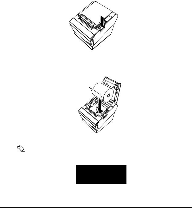
1.Make sure the host has not sent a printing command to the printer, and press the cover open button to open the printer cover. If the printer cover does not open, a probable cause is that the autocutter is locked. If this happens, refer to “Paper jam.”
|
P |
|
E |
OW |
ER |
RR |
|
|
FOUTPAPER |
OR |
|
|
|
|
EED |
|
|
Figure 1-5 Cover open button
2. Load the roll paper.
POW |
ER |
|
ERROR |
||
|
||
FOUTPAPER |
|
|
EED |
|
Figure 1-6 Loading paper
Note:
When loading the roll paper, pay attention to the direction that the roll paper is fed out of the printer.
Figure 1-7 Paper direction
1-6 Product Overview |
Rev. A |
TM-T88II/T88III Technical Reference Guide
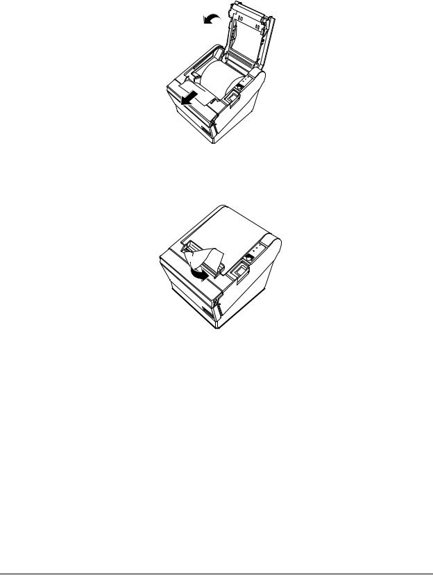
3.Pull out the roll paper toward you.
4.Close the printer cover.
POWER
ERROR
FOUTPAPER
EED
Figure 1-8 Closing the printer cover
5. Tear off the leading edge of the roll paper using the manual cutter.
|
POW |
ER |
|
E |
|
|
RR |
|
O PAP |
OR |
|
F UT |
ER |
|
EED |
|
|
Figure 1-9 Tear off paper
1.3.2.2 Replacing Paper
Follow the procedure below to replace roll paper.
1.Open the printer cover, and remove the core of the previously used roll paper.
2.Insert the new roll paper following the procedure in “Installing Roll Paper” (page 1-6).
1.3.3Power Switch Cover
Install the power switch cover that comes with the TM-T88II/TM-T88III onto the printer to prevent inadvertent changing of the power switch, to prevent tampering, and to improve the appearance of the printer.
To reset the TM printer when the power switch cover is installed, insert a long, thin object (such as the end of a paper clip) into the hole in the power switch cover and press the power switch.
Rev. A |
Product Overview 1-7 |

1.3.4 Shipping Procedures
Do the following before shipping the printer.
1.Press the power switch to turn the power off.
2.Make sure the POWER LED is out.
3.Remove the power supply connector.
4.Pack the printer, keeping the top and bottom correctly oriented.
1-8 Product Overview |
Rev. A |

TM-T88II/T88III Technical Reference Guide
Chapter 2
Setup
Before using the printer, you need to make various settings to increase the printer's functionality. Configure the printer appropriately depending on the environment.
1. Install the printer (page 2-2)
Detailed setup
2.Set the DIP switches (page 2-2)
3.Set the roll paper near-end detector (page 2-7)
Note: Detailed setup sometimes can be omitted.
4.Connect the printer to the host computer (page 2-8)
5.Connect the power supply and cash drawer (page 2-15)
6.Install the driver (page 2-16)
End
Figure 2-1 Setup flowchart
Rev. A |
Setup 2-1 |

2.1 Installing the Printer
In addition to regular horizontal installation, the printer can be hung on a wall using the optional WH-10 Wall Hanging Bracket Set.
2.1.1Precautions for Horizontal Installation
Install the printer in a flat, horizontal position.
Avoid locations susceptible to dust and other foreign matter.
Be sure to avoid bumping so that the printer is not exposed to strong impact during operation.
Avoid placing the printer on top of the power supply or other cables or other objects.
2.1.2Precautions for Wall Installation
Make the following settings on the printer when you hang it on a wall. For details, refer to the installation manual provided with the optional WH-10 Wall Hanging Bracket Set.
•Install the roll paper stopper
•Adjust of near-end detector
•Install the WH-10
For other details, refer to the installation manual provided with the optional WH-10 Wall Hanging Bracket Set option.
2.2 Setting the DIP Switches
On this printer, you can make various settings with DIP switches.
 Note:
Note:
Serial interface communication conditions must be set on serial interface model printers.
2.2.1 DIP Switch Positions and Steps for Changing DIP Switch Settings
Follow the steps below to change the DIP switch settings.
 CAUTION:
Before you remove the DIP switch cover, turn the printer off. Otherwise, a short-circuit may cause the printer to malfunction.
1. Make sure the power supply for the printer is turned off.
2-2 Setup |
Rev. A |

TM-T88II/T88III Technical Reference Guide
2. Unscrew the screw to remove the DIP switch cover from the base of the printer.


 DSW1
DSW1


 DSW2
DSW2
Figure 2-2 Removing the DIP switch cover
3.Set the DIP switches as desired, using the tip of a tool, such as a small screwdriver.
4.Attach the DIP switch cover, and screw in place.
 Note:
Note:
New DIP switch settings are enabled after the printer is turned on.
2.2.2 DIP Switch Functions
The DIP switch functions depend on your printer’s interface specifications.
2.2.2.1 DIP switch settings for serial interface specifications
Note that the functions of DIP SW1-7, 1-8, and 2-5 differ on the TM-T88II and TM-88III. (The functions of other DIP switch settings are the same.)
 Note:
Note:
* Factory setting
Table 2-1 Switch bank 1 settings
SW |
Function |
ON |
OFF |
|
|
|
|
1-1 |
Data receive error |
Ignore |
“?” is printed * |
|
|
|
|
1-2 |
Receive buffer size |
45 bytes |
4KB * |
|
|
|
|
1-3 |
Handshake |
XON/XOFF |
DTR/DSR * |
|
|
|
|
1-4 |
Bit length |
7 bits |
8 bits * |
|
|
|
|
1-5 |
Parity check |
Yes |
No * |
|
|
|
|
1-6 |
Parity selection |
Even |
Odd * |
|
|
|
|
1-7, |
Baud rate selection |
|
|
1-8 |
(See the “Baud rate selection” tables below. (Note that the settings differ on the TM-T88II and TM-T88III.)) |
||
|
|
|
|
For details on DIP SW1-2: Receive buffer size, also refer to DIP SW2-5: Cancellation of receive buffer full BUSY state.
Rev. A |
Setup 2-3 |

Table 2-2 Baud rate selection (DIP SW1-7, 1-8)
TM-T88II
Baud rate |
Switch no. |
|
|
|
|
(BPS) |
1-7 |
1-8 |
|
|
|
2400 |
ON |
ON |
|
|
|
4800 |
OFF |
ON |
|
|
|
9600 * |
ON |
OFF |
|
|
|
19200 |
OFF |
OFF |
|
|
|
TM-T88III
Baud rate |
Switch no. |
|
|
|
|
(BPS) |
1-7 |
1-8 |
|
|
|
38400 |
ON |
ON |
|
|
|
4800 |
OFF |
ON |
|
|
|
9600 * |
ON |
OFF |
|
|
|
19200 |
OFF |
OFF |
|
|
|
Table 2-3 Switch bank 2 settings
SW |
Function |
ON |
|
OFF |
|
|
|
|
|
2-1 |
Handshake (BUSY) conditions |
Receive buffer full |
|
Printer offline or |
|
|
|
|
receive buffer full * |
|
|
|
|
|
2-2 |
Reserved (do not change setting) |
Fixed to OFF |
|
|
|
|
|
|
|
2-3, 2-4 |
Print density selection/low-power mode |
(See separate table.) |
|
|
|
|
|
|
|
2-5 |
Conditions for canceling receive buffer BUSY state |
(See separate table.) |
|
|
|
|
|
|
|
2-6 |
Reserved (do not change setting) |
Fixed to OFF |
|
|
|
|
|
|
|
2-7 |
Pin # 6 reset signal |
Used |
|
Not used * |
|
|
|
|
|
2-8 |
Pin # 25 reset signal |
Used |
|
Not used * |
|
|
|
|
|
For details on DIP SW2-1: BUSY conditions, also refer to “Busy State” (page 3-11).
Table 2-4 Print density selection (DIP SW2-3, 2-4)
|
|
Switch No. |
|
|
|
|
|
Level |
Print density |
2-3 |
2-4 |
|
|
|
|
— |
Low-power mode |
ON |
ON |
|
|
|
|
1 |
Regular print density * |
OFF |
OFF |
|
|
|
|
2 |
↔ |
ON |
OFF |
|
|
|
|
3 |
Heavy print density |
OFF |
ON |
|
|
|
|
Table 2-5 Conditions for canceling receive buffer BUSY state (DIP SW2-5)
TM-T88II
Conditions to cancel receive buffer |
Switch No. |
|
|
||
2-5 |
||
BUSY state |
||
|
|
|
BUSY state canceled when 26 bytes or |
Fixed to |
|
more remain in receive buffer |
OFF |
|
|
|
TM-T88III
Conditions to cancel receive buffer |
Switch No. |
BUSY state (enabled only when DIP |
|
|
|
SW1-2 is OFF) |
2-5 |
|
|
BUSY state canceled when 138 bytes |
ON |
remain in receive buffer |
|
|
|
BUSY state canceled when 256 |
OFF |
bytes * remain in receive buffer |
|
|
|
2-4 Setup |
Rev. A |

TM-T88II/T88III Technical Reference Guide
 Note:
Note:
With the TM-T88III, the DIP SW2-5 setting is enabled only when DIP SW1-2 is set to OFF and the receive buffer is set to 4KB.
With the older TM-T88II model, be sure to set DIP SW2-5 to OFF before use. Otherwise, the printer may no longer function correctly.
When the TM-T88II is used or when the TM-T88III is used with DIP SW1-2 set to ON, the BUSY state is canceled when “26 bytes remaining in receive buffer” are reached, regardless of DIP SW2-5 setting.
Do not change the settings of DIP SW2-2 and SW2-6. Otherwise, the printer may no longer function correctly.
2.2.2.2 DIP switch settings for other interface specifications
The following DIP switch functions are for parallel interface/USB/Ethernet model printers.
 Note:
Note:
* Factory setting
Table 2-6 Parallel/USB/Ethernet DIP switch bank 1
SW |
Function |
ON |
OFF |
|
|
|
|
1-1 |
Automatic line feed |
Enabled at all times |
Disabled at all times * |
|
|
|
|
1-2 |
Receive buffer size |
45 bytes |
4KB * |
|
|
|
|
1-3, 1-8 |
Not defined |
— |
— * |
|
(Always use printer with these switches set to OFF.) |
|
|
|
|
|
|
Table 2-7 Parallel/USB/Ethernet DIP switch bank 2
SW |
Function |
ON |
OFF |
|
|
|
|
2-1 |
Handshake (BUSY conditions) |
• Receive buffer full |
• Offline * |
|
|
|
• Receive buffer full |
|
|
|
|
2-2 |
Reserved (do not change setting) |
Fixed to OFF |
|
|
|
|
|
2-3, 2-4 |
Print density selection/low-power mode |
(See separate table.) |
|
|
|
|
|
2-5 |
Conditions for canceling receive buffer BUSY state |
(See separate table.) |
|
|
|
|
|
2-6, 2-7 |
Reserved (do not change setting) |
Fixed to OFF |
|
|
|
|
|
2-8 |
Pin #31reset signal (do not change setting) |
Fixed to ON |
|
|
|
|
|
DIP SW2-1: For details on the BUSY condition, also refer to “Busy State” (page 3-11).
Rev. A |
Setup 2-5 |

Table 2-8 |
Selection of print density |
|
|
|
||
|
|
|
|
|
|
|
|
|
|
|
Switch no. |
|
|
|
|
|
|
|
|
|
Level |
|
Print density |
|
2-3 |
2-4 |
|
|
|
|
|
|
|
|
1 |
|
Low-power mode |
|
ON |
ON |
|
|
|
|
|
|
|
|
2 |
|
Regular print density * |
|
OFF |
OFF |
|
|
|
|
|
|
|
|
3 |
|
↔ |
|
ON |
OFF |
|
|
|
|
|
|
|
|
4 |
|
Heavy print density |
|
OFF |
ON |
|
|
|
|
|
|
||
Table 2-9 Conditions for canceling receive buffer BUSY state |
||||||
|
|
TM-T88II |
|
|
TM-T88III |
|
Conditions to cancel receive buffer BUSY |
Switch no. |
|
|
||
2-5 |
||
state |
||
|
|
|
BUSY state canceled when 26 bytes or |
Fixed to |
|
more remain in receive buffer |
OFF |
|
|
|
Conditions to cancel receive buffer BUSY |
Switch no. |
|
|
|
|
state (enabled only when DIP SW1-2 OFF) |
2-5 |
|
|
BUSY state canceled when 138 bytes |
ON |
remain |
|
|
|
BUSY state canceled when 256 bytes |
OFF |
remain * |
|
|
|
 Note:
Note:
With the TM-T88III, the DIP SW2-5 setting is enabled only when DIP SW1-2 is set to OFF and the receive buffer is set to 4KB.
With the TM-T88II, be sure to set DIP SW2-5 to OFF before use. Otherwise, the printer may no longer function correctly.
When the TM-T88II is used or when TM-T88III is used with DIP SW1-2 set to ON, the BUSY state is canceled when “26 bytes remaining in receive buffer” are reached regardless of the setting of DIP SW2-5.
Do not change the settings of DIP SW2-2 and SW2-6. Otherwise, the printer may no longer function correctly.
2-6 Setup |
Rev. A |
TM-T88II/T88III Technical Reference Guide
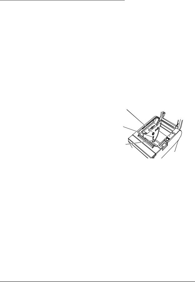
2.3 Adjusting the Roll Paper Near-End Detector
Below are two situations where a roll paper NE detector adjustment is required.
To adjust the detection position to suit the diameter of the roll paper core used.
To adjust the detection position of remaining amount of paper.
 Note:
Note:
Since roll paper cores vary slightly in shape, depending on paper roll design and manufacturing tolerances, it impossible to detect the remaining paper exactly. Use roll paper with a core inner diameter of 12 mm {0.47"} and outer diameter of 18 mm {0.71"} so that the NE detector can detect the remaining paper as accurately as possible.
Follow the procedure below to adjust the roll paper NE detector position.
1.Open the roll paper cover, and remove the roll paper.
2.Loosen the adjustment screw fastening the detector, and align the upper edge of the positioning plate with the adjustment position. Adjustment positions are as follows:
Adjustment screw
Adjustment |
Remaining amount of roll |
|
|
position |
paper (outer diameter: mm) |
Positioning plate |
|
|
|
||
Upper |
Approx. 27 |
||
|
|||
|
|
|
|
Lower |
Approx. 23 |
|
|
|
|
|
Detection lever
 POWER ERROR FOUTPAPER EED
Figure 2-3 NE detector positions
 Note:
Note:
The adjustment screw is set to the lower position before shipment.
3.Tighten the adjustment screw.
4.After adjustment, make sure that the detection lever operates smoothly.
5.Load the roll paper.
6.Close the roll paper cover.
Rev. A |
Setup 2-7 |
 Loading...