


THERMAL LINE PRINTER
TM-T60/T60P
TM-T80/T80P
Operator’s Manual
400206500
All rights reserved. No part of this publication may be reproduced, stored in a retrieval system, or transmitted in any form or by any means, mechanical, photocopying, recording, or otherwise. without the prior written permission of Seiko Epson Corporation. No patent liability is assumed with respect to the use of the information contained herein. While every precaution has been taken in the preparation of this book, Seiko Epson Corporation assumes no responsibility for errors or omissions. Neither is any liability assumed for damages resulting form the use of the information contained herein.
Neither Seiko Epson Corporation nor its affiliates shall be liable to the purchaser of this product or third parties for damages, losses, costs, or expenses incurred by purchaser or third parties as a result of; accident. misuse, or abuse of this product or modifications, repairs, or alterations to this product, or (excluding the U . S .) failure to strictly comply with Seiko Epson Corporation’s operating and maintenance instructions.
Seiko Epson Corporation shall not be liable, against any damages or problems arising from the use of any options or any consumable products other than those designated as Original Epson Products or Epson Approved Products by Seiko Epson Corporation.
Epson and ESC/POSTM are registered trademarks of Seiko Epson Corporation.
NOTICE:
The contents of this manual are subject to change without notice. Copyright © 1993 by Seiko Epson Corporation, Nagano, Japan
FCC-CLASS A
FCC COMPLIANCE STATEMENT FOR AMERICAN USERS
This equipment has been tested and found to comply with the limits for a Class A digital device, pursuant to Part 15 of the FCC Rules. These limits are designed to provide reasonable protection against harmful interference when the equipment is operated in a commercial environment.
This equipment generates, uses, and can radiate radio frequency energy and, if not installed and used in accordance with the instruction manual, may cause harmful interference to radio communications. Operation of this equipment in a residential area is likely to cause harmful interference in which case the user will be required to correct the interference at his own expense.
WARNING
The connection of a non-shielded printer interface cable to this printer will invalidate the FCC Certification of this device and may cause interference levels which exceed the limits established by the FCC for this equipment. You are cautioned that changes or modifications not expressly approved by the party responsible for compliance could void your authority to operate the equipment.
FOR CANADIAN USERS
This digital apparatus does not exceed the Class A limits for radio noise emissions from digital apparatus as set out in the radio interference regulations of the Canadian Department of Communications.
Le pésent appareil numérique n’émet pas de bruits radioélectriques dépassant les limites applicables aux appareils numériques de Classe A prescrites dans le réglement sur le brouillage radioélectriques édicte par le Ministére des Communications du Canada.
- i -

INTRODUCTION
The TM-T6O/T6OP and the TM-T8O/T8OP are a one-station printer for ECR and POS use which can be used for printing the results of scaling or measuring.
The main features are as follows:
. Light and ultracompact
. High-speed printing
. low-noise thermal printing
. High reliability due to a low number of moving parts
. Maintenance such as head cleaning performed easily
• Command protocol based on ESC/POSTM, a widely used standard
. Four-way routing of the interface cable, drawer control cable, and power cable on either side, underneath, or out the back of the case
. Easy access to the power switch on the front of the printer body; access to both sides and the back not necessary
. Bar code printing possible using a bar code command
. 90’ character rotation possible
. Repeated operation and copy printing possible through macro definition
. Drawer control possible using the drawer-kick interface
I |
I n t e r f a c e P a p e r W i d t h |
|
||
TM-T60 |
Serial |
60mm |
|
|
TM-T6OP |
Parallel |
|
|
|
|
|
|
||
TM-T80 |
Serial |
8Omm |
|
|
|
|
|||
TM-T8OP |
Parallel |
|
|
|
|
|
|
||
Please be sure to read the instructions in this manual carefully before using your new Epson printer.
The TM-T60 and the TM-T80 have a serial interface connector and the TMT6OP and TM-T8OP have a parallel interface one.
Except for the defferent roll width accommodated by the two printers, the functions provided by the TM-T6O/T60P and the TM-T8O/T8OP are the same. Most of the illustrations used in this operation manual show the TM-T6O/T6OP.
- i i -

About this manual
I . SETTING UP]
* Chapter 1 contains information on unpacking the printer, choosing the place for the printer, and names and functions of parts.
* Chapter 2 and Chapter 3 contain information on connecting and setting up the printer.
* Chapter 4 contains information on testing the printer.
II . REFERENCE1
*Chapter 5 contains information on using the printer.
*Chapter 6 contains information on software control including printer
command descriptions.
A P P E N D I X
Appendixes contain information on general specifications, character code tables and a list of commands.
CONTENTS
I . SETTlNG UP |
|
|
|
||
Chapter 1 Unpacking the Printer |
|
2 |
|||
l - l |
Checking the Contents of the Box . . . . . . . . . . . . . . . . . . . . . . . . . . . . . . . . . . . . . . . . |
2 |
|||
l - 2 Choosing a Place for the Printer |
. . . . . . . . . . . . . . . . . . . . . . . . . . . . . . . . . . . . . . . . . . . . . |
3 |
|||
|
|||||
l-3 Removing the Protective Material . . . . . . . . . . . . . . . . . . . . . . . . . . . . . . . . . . . . . . . . . . . . . |
3 |
||||
l - 4 |
Names and Functions of Parts . . . . . . . . . . . . . . . . . . . . . . . . . . . . ................. |
4 |
|||
Chapter 2 |
Before Setting Up |
|
6 |
||
2- 1 |
Connecting the Power Supply to the Printer . . . . . . . . . . . . . . . . . . . . . . . . . . . . . |
6 |
|||
2 - 2 |
Connecting the Host Computer to the Printer . . . . . . . . . . . . . . . . . . . . . . . . . . . |
7 |
|||
Chapter 3 |
Installing the Parts |
|
9 |
||
3 - 1 Installing the Roll Paper
3-2 Adjusting the Paper-End
3 -3 Setting the DIP Switches
Chapter 4 The Self Test
. . . . . . . . . . . . . . . . . . . . . . . . . . . . . . . . . . . . . . . . . . . . . . . . . . . . . . . .
Detector . . . . . . . . . . . . . . . . . . . . . . . . . . . . . . . . . . . . . . . . . .
. . . . . . . . . . . . . . . . . . . . . . . . . . . . . . . . . . . . . . . . . . . . . . . . . . . . .
9
12
14
17
4 - 1 The Open-Cover Detector . . . . . . . . . . . . . . . . . . |
. . . . . . . . . . . . . . . . . . . . . . . . . . . . . I . . . . . . |
17 |
4 - 2 Checking Operation with the Setf Test |
. . . . . . . . . . . . . . . . . . . . . . . . . . . . . . . . . . . . |
18 |
. . .
- - I l l -

II. REFERENCE1 |
|
|
|
|
|
|
Chapter 5 Cautions while Using the Printer |
20 |
|||||
5 - l Panel Switches and Commands |
............................................. |
20 |
||||
|
||||||
5 - 2 |
Printable Area ..................................................................... |
21 |
||||
5 - 3 |
Miscellaneous Notes ............................................................ |
22 |
||||
5-4 Error Correction |
.................................................................. |
25 |
||||
|
|
|
||||
5-5 Cleaning the Head ............................................................... |
27 |
|||||
Chapter 6 Software Control |
|
28 |
||||
6 - 1 |
Printer Control ..................................................................... |
28 |
||||
6 - 2 |
Command Descriptions ......................................................... |
29 |
||||
6-3 |
Commands ........................................................................ |
30 |
||||
6 -4 Program Descriptions ......................................................... |
52 |
|||||
APPENDIX |
|
|
|
59 |
||
APPENDIX A General Specifications ............................................. |
59 |
|||||
APPENDIX B Connectors ............................................................ |
63 |
|||||
APPENDIX C Interfaces |
............................................................ |
66 |
||||
APPENDIX D Notes on Using the Drawer kick-out Connector ------------ |
71 |
|||||
APPENDIX E Character Code Tables .......................................... |
74 |
|||||
APPENDIX F Command |
|
Summary ................................................ |
77 |
|||
- i v -

I. SETTING UP
Chapter 1 Unpacking the Printer
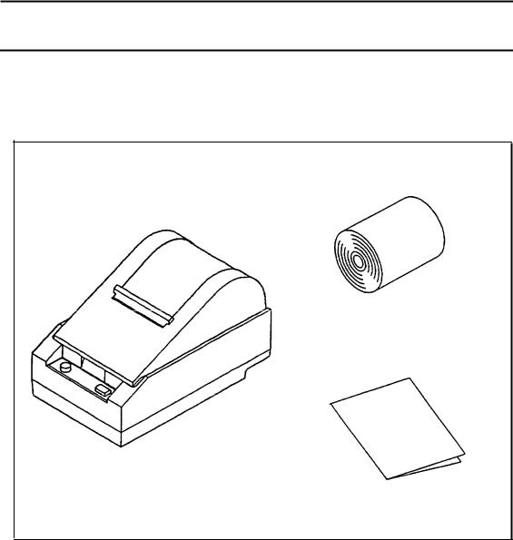
1 - 1 Checking the Contents of the Box
nChecking the parts
Remove the printer and other parts from the box.
• Roll paper
• Printer
• Operator’s Manual
Make sure no parts are missing or damaged.
If you find any damaged or missing parts, please contact your dealer for assistance.
H Maintenance
Keep the packing case and packing materials in case you ever need to transport or store your printer.
nOptional parts
Power supply (PS-130)) Power supply DC cable (1.5m)
- 2 -

1 - 2 Choosing a Place for the Printer
nAvoid locations that are subject to direct sunlight or excessive heat (near heaters).
nAvoid using or storing the printer in places subject to excessive temperatures or moisture.
nDo not use or store the printer in a dusty or dirty location.
nWhen setting up the printer, choose a stable, horizontal location. Intense vibration or shock may damage the printer.
nEnsure the printer has enough space to be used easily.
1-3 Removing the Protective Material
An orange plastic spacer is put into the printing mechanism section to protect the printer from damage during transportation. Before you turn on the printer, be sure to remove the spacer according to the following steps.
1.Open the printer cover.
2.Raise the head-open lever to remove the spacer.
3.Store it in the hollow space. Re-insert the space when transporting.
4.Lower the head-open lever.
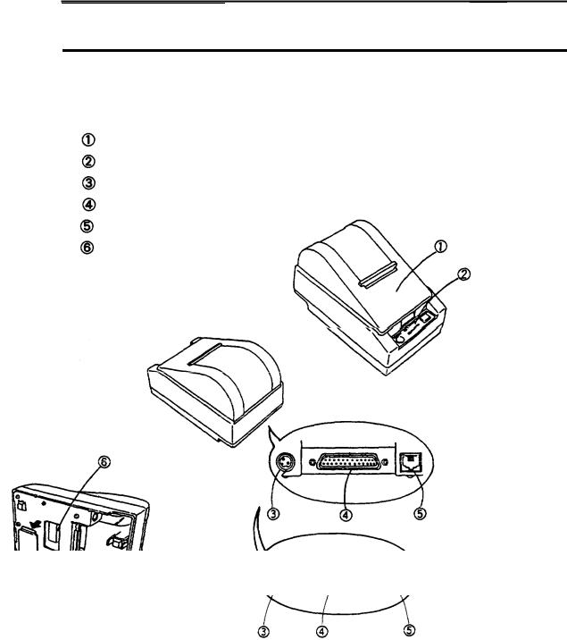
1 - 4 Names and Functions of Parts
n Part names
Printer cover
Operation panel
Power connector
Interface connector
Drawer-kick connector
DIP switches (*1)
TM-T60/T80
TM-T60P/T8OP
* 1: The DIP switches are located behind the small cover on the bottom of the printer.
- 4 -
Operation panel
Panel switches
P O W E R
Press the POWER button to turn the printer ON and OFF. When the button is pushed down, the power is on. When pressed again, the button returns to its original position, turning the power off.
• Do not turn the power off during printing.
P A P E R F E E D
Press the PAPER FEED button to feed roll paper.
• You cannot feed paper when the printer cover is open.
Panel lights (LED)
 POWER (green)
The POWER light is on when power is turned on.
ERROR (red)
The ERROR light is on when the printer cover is not closed completely, or when the paper roll is near the end. The light blinks during an error condition, or when waiting for data during macro execution.
PAPER (red)
The PAPER light is on when roll paper is not loaded, or when the paper roll is near the end.
- 5 -

Chapter 2 Before Setting Up
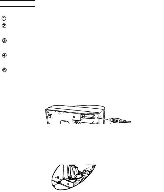
2- 1 Connecting the Power Supply to the Printer
nPlugging in AC adapter
The printer must be connected to an external power supply.
Be sure to use a power cable that matches the specifications of both
the printer and the power supply unit. |
|
|
--------------------------------------------------------------------- |
II |
|
CAUTIONS: |
||
I |
||
• Before connecting the printer to the power supply, make sure |
|
|
that the voltage (24 VDC) and power specifications match the |
I |
|
printer’s requirements. |
||
• Using an incorrect power supply can cause serious damage to |
II |
|
II the printer. |
||
Connect the power unit according to the following procedure. |
|
|
Make sure the printer and the power unit are turned off. |
|
Plug the power cable’s connector into the printer’s power connector with the arrow mark facing downward.
Plug the power cord into the outlet, and turn on the power unit. TM-T60/T80
- 6 -
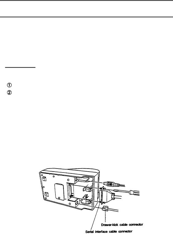
2-2 Connecting the Host Computer to the Printer
nConnecting the interface cable
Connect the printer to a host ECR (host computer) using an interface cable matching the specifications of the printer and the host ECR (host computer).
TM-T6O/T80
Connect the interface cable according to the following procedure. Turn off the printer, power unit, and host computer.
Plug the interface cable connector into the interface connector on the printer; then insert a screwdriver between the rear rubber feet and fasten the screws on both sides of the connector.
 Plug the drawer-kick cable connector into the drawer-kick connector on the printer (if this connector is covered, you cannot attach a drawer-kick cable to your printer).
•Remove the drawer-kick cable by pressing in on the connector’s clip and pulling out.
- 7 -
TM-T60P/T80P
Connect the interface cable according to the following procedure. Turn off the printer, power unit, and host computer.
Plug the interface cable connector into the interface connector on the printer.
Squeeze the wire clips together until they lock in place on both sides of the connector.
Attack the ground wire to the ground connector on the right side of the interface connector.
Plug the drawer-kick cable connector into the drawer-kick connector on the printer (if this connector is covered, you cannot attach a drawer-kick cable to your printer).
- 6 -

Chapter 3 Installing the Parts
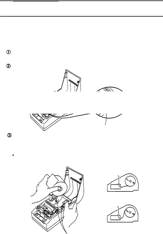
3-l Installing the Roll Paper
 Installing the roll paper
Be sure to use roll paper that matches the printers specifications.
Using scissors, cut the leading edge of the roll paper perpendicular to the paper feed direction.
Open the printer cover and raise the release-lever toward you.
Release lever
 Load the roll paper while Iightiy pressing the right roll paper holder outward. Release the holder after fitting the paper core onto the holder. Make sure the roll paper turns freely.
When loading roll paper, make sure to insert so that it rotates in the correct direction.
Correct
Incorrect
Roll paper holder
- 9 -
Chapter 3 Installing the Parts
3-l Installing the Roll Paper
 Installing the roll paper
Be sure to use roll paper that matches the printers specifications.
Using scissors, cut the leading edge of the roll paper perpendicular to the paper feed direction.
Open the printer cover and raise the release-lever toward you.
Release lever
Load the roll paper while Iightly pressing the right roll paper holder outward. Release the holder after fitting the paper core onto the holder. Make sure the roll paper turns freely.
When loading roll paper, make sure to insert so that it rotates in the correct direction.
Correct
Incorrect
Roll paper holder
- 9 -

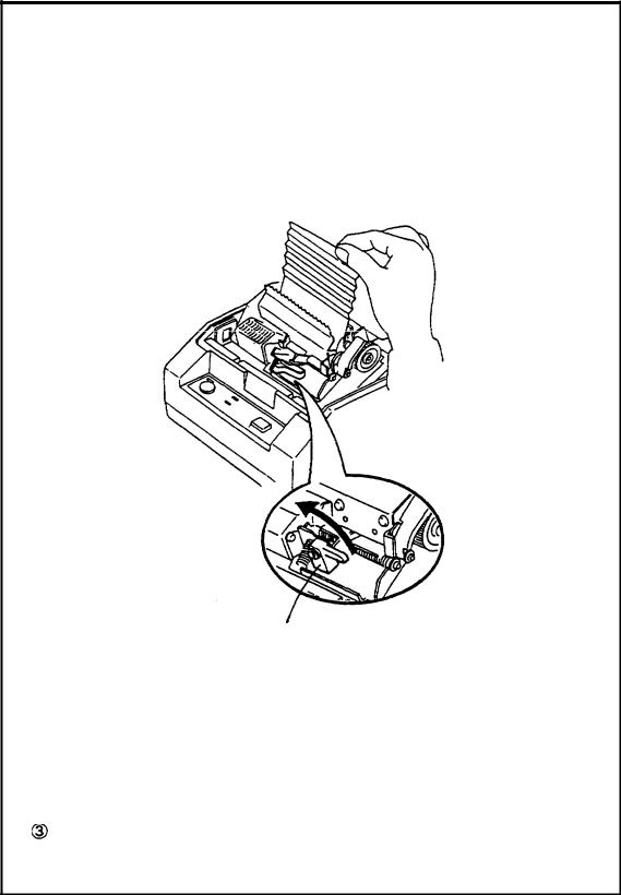
Insert the edge of the roll paper into the paper slot and turn the paper-feed knob in the direction of the arrow to feed the paper 5 cm beyond the tear-off edge.
• Don’t turn the paper-feed knob when the release lever is down.
Paper-feed knob
Raise the head-open lever, unroll the paper a little and pull lightly from the roll paper side to eliminate twist or misalignment. Retighten the roll paper to remove any slack. Roth edges of the paper should be aligned parallel to the paper roll.
Push down the release lever and then the head-open lever. Tear off any extra paper at the tear-off edge by pulling the paper toward you.
 Close the
- I O -
nRemoving jammed paper
Removing jammed paper according to the following steps.  Open the printer cover and raise the head-open lever.
r _ _ _ - - - |
_ _ _ - - |
_ _ _ - - - - - - - - - - - - - - - - - - - - - - - - - - - - - - - - - - - - - - - - - - - - - - - - - - - - - - - - - - - - |
. |
I |
|
|
|
CAUTION:
* The print head is very hot immediately after printing.
Always remove jammed paper after the print head has cooled.
Head-open lever
I
I
I
 Remove any jammed paper. r---------------------------------------------------------------------------
CAUTION:
. Never touch the print head.
I- - - - - - - - - - - - - - - - - - - - - - - - - - - - - - - - - - - - - - - - - - - - - - - - - - - - - - - - - - - - - - - - - - - - - - - - - - - -
I
I
I
III
I
Push the head-open lever down. Reload roll paper and close the printer cover. See 3-l 
- 1 1 -
3 -2 Adjusting the Paper-End Detector
nThe paper-end detector
The paper-end detector senses when the paper is nearing its end and turns on the PAPER lamp.
The paper-end detector can be adjusted according the thickness of the Paper.
nHow to adjust the paper-end detector
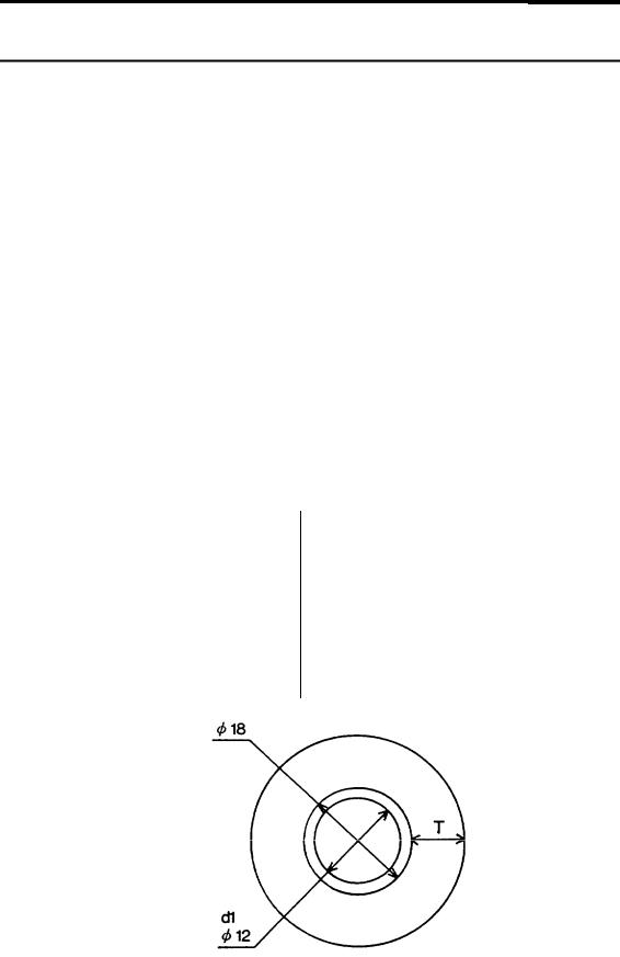
Roll paper may differ in spool size, so it may be necessary to adjust the paper-end detector.
 Use the specified paper roll with a cure inside diameter (d1) of 12mm and an outside diameter (d2) of 18 mm.
 The thickness of the spool can vary; use the table to determine the paper-end detector adjustment.
Table 3-l. Adjustment Values of the Paper-end Detector
Adjustment Value |
Dimension of T (mm) |
||
|
|
|
|
|
# l |
Approx. 0 |
|
---------------------------------------------- |
|||
. |
#2 |
Approx. 2 |
|
---------------------------------------------#3 |
Approx. 4 |
||
|
|||
--------------------------------------------- |
|||
|
#4 |
Approx. 6 |
|
---------------------------------------------- |
|||
|
#5 |
Approx. 8 |
|
---------------------------------------------- |
|||
|
#6 |
Approx . 10 |
|
|
d2 |
|
|
- 1 2 -
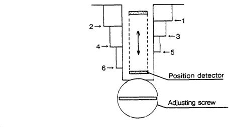
 Loosen the adjusting screw that holds the paper-end detector.
Then set the top of the positioning plate to the appropriate adjustment position, and tighten the adjusting screw.
NOTES:
1 . The T dimensions corresponding to the adjustment values in
I
II the table are caluculated from standard measurements; some II variations in the actual mechanism.
2. After adjusting, ensure that the detector operates smoothly.
L - - - - - - |
_ - - - |
_ _ _ _ - - - - - - - - - - - - - - - - - - - - - - - - - - - - - - - - - - - - - - - - - - - - - - - - - - - - - - - - - - - |
i I
I
J
- 1 3 -
3 -3 Setting the DIP Switches
nLocating the DIP switches
On the underside of your printer are a number of DIP switches that can be set to perform a number of different functions.
-You can change the function of your printer by turning DIP switches on or off.
-Current DIP-switch settings are printed out during the self test.
-The switches numbered from left to right are SW1-1 through SW1-10 (TM-T6O/T80) or SW1-1 through SW1-5 (TM-T6O/T80P).
-Each switch functions as described in the lists on the following page.
nSetting the DIP switches
Follow these steps when changing DIP-switch settings.
ŒTurn the printer power supply off.
•Remove the small cover on the printer’s bottom to expose the DIP switches.
Flip the DIP switches using tweezers or other narrow-ended tool.
ŽSwitches in the up position are ON; those in the down position are OFF.
TM-T6O/T8O
T M - T 6 ( ) p / T 8 o P
r - - - - - - - - - - - - - - - - - - - - - - - - - - - - - - - - - - - - - - - - - - - - - - - - - - - - - - - - - - - - - - - - - - - - - - - - - - - |
I |
I |
|
NOTE: |
I |
I |
- Changes made with the power on have no effect until the power
I |
I |
I supply is turned off and then on again. |
I |
I |
I |
I- - - - - - - - - - - - - - - - - - - - - - - - - - - - - - - - - - - - - - - - - - - - - - - - - - - - - - - - - - - - - - - - - - - - - |
- - - - - - -I |
- 1 4 -

nTM-T60/T60 DIP-Switch Functions
Table 3-2 DIP-Switch Functions (On the bottom of the case)
DIP SW1 |
|
|
ON |
|
|
|
|
|
|
OFF |
|
|
SW- 1 |
Ignores data reception errors |
|
Prints “?” for data reception |
|
||||||||
|
|
|
|
|
. |
|
errors |
|
|
|
|
|
- - - - - - - - - - - - - - - - - -SW-2 Data buffer |
--------------------- |
|
|
|
|
|
|
|||||
45 bytes |
|
|
Data buffer 4 Kbytes |
|
||||||||
- - - - - - - - - - - - - - |
--------------------------------------------------------- |
|
||||||||||
SW3 XON/XOFF |
control |
|
|
|
DTR/DSR |
control |
|
|||||
- - - - - - - - - - - - |
--------------------------------------------------------- |
|
||||||||||
SW-4 Parity |
|
|
|
|
No Parity |
|
|
|
|
|||
---------------------- --------------------------------------------------------- |
|
|||||||||||
SW-5 Even parity |
|
|
|
|
Odd parity |
|
|
|
|
|||
-------------------- --------------------------------------------------------- |
|
|||||||||||
SW-6 |
Change baud rate (Refer to Table 3-3) |
|
||||||||||
S W - 7 |
|
|||||||||||
|
|
|
|
|
|
|
|
|
|
|||
S W - 8 |
|
Change print density (Refer to Table 3-4) |
|
|||||||||
|
|
|||||||||||
S W - 9 |
|
|
||||||||||
w - 1 0 |
|
Normally OFF |
|
|
|
|
||||||
|
|
|
Table 3-3. Baud Rate Selection |
|
|
|
|
|||||
|
|
|
|
|
|
|||||||
|
|
Baud Rate SWl - 6 SW1 - 7 |
|
|||||||||
|
|
|
1200 bps |
O N |
|
O N |
|
|
|
|
||
|
|
|
4800 |
|
OFF |
|
O N |
|
|
|
|
|
|
|
|
9600 |
|
O N |
|
O F F |
|
|
|
|
|
|
|
19200 |
|
O F F |
|
O F F |
|
|
|
|
||
|
|
Table 3-4. Print Density Selection |
|
|||||||||
|
|
|
|
|
|
|
|
|
|
|
|
|
|
|
Print Density |
SW1 |
-8 |
|
SW1 -9 |
|
Level |
|
|
||
|
|
LIGHT |
ON |
|
ON |
1 |
|
|
||||
|
|
|
|
OFF |
|
OFF |
2 |
|
|
|||
|
|
|
|
--------------------------------------- |
|
|
||||||
|
|
|
|
ON |
|
OFF |
3 |
|
|
|||
|
|
DARK |
--------------------------------------- |
|
|
|||||||
|
|
OFF |
|
ON |
4 |
|
|
|||||
- 1 5 -

nTM-T60P/T80P DIP-Switch Functions
Table 3-5. DIP-Switch Functions (On the bottom of the case)
DIP SW1 |
ON |
|
OFF |
SW-l Auto-feed function is always |
Depends on AUTO FEED XT |
||
valid |
|
signal |
|
-------------------------------------------------------------------------------------------- |
|||
SW-Z Data buffer 0 byte |
Data buffer 4 Kbytes |
||
------------------------------------------------------------------------- |
|||
S W - 3 |
|
|
|
Character print density (Refer to Table 3-6) |
|||
S W - 4 |
|
|
|
----------------------------------------------------------------------------- |
|||
S W - 5 |
Normally OFF |
|
|
Table 3-6. Print Density Selection |
|
||
P r i n t D e n s i t y S W 1 - 3 S W 1 - 4 L e v e l |
|||
LIGHT |
O N |
O N |
1 |
|
O F F |
O F F |
2 |
|
O N |
OFF |
3 |
DARK |
OFF |
O N |
4 |
- 16-

Chapter 4 The Self Test
4 - 1 The Open-Cover Detector
nThe open-cover detector
This unit has an open-cover detector located inside the printer cover.
-Data is not printed when the printer cover is open.
-Opening the cover sets the printer OFF LINE; data cannot be received when the printer is OFF LINE.
-Paper cannot be fed with the paper-feed switch when the printer cover is open.
nReturning the printer ON LINE
-Closing the cover sets the printer ON LINE automatically.
I----------------------------------------- |
- - - - - - - - - - - - - - - - - - - - - - - - - - - -II |
|
|
CAUTION: |
I |
I |
The printer cover cannot be closed unless the head-release lever |
I |
I |
|
|
I |
|
|
I |
and the head-open lever are down. |
I |
I |
I |
|
I |
|
|
I. |
- - - - - - - - - - - - - - - - - - - - - - - - - - - - - - - - - - - - - - - - - - - - - - - - - - - - - - - - - - - - - - - - - - - - |
- |
- 1 7 -

4 -2 Checking Operation with the Self Test
nThe purpose of the self test
The self test checks whether the printer has any problems. When the printer does not function properly, please contact the dealer.
nThe self test checks the following
- Control circuit functions |
- Control ROM version |
- Printer mechanism |
. RAM checking |
- Print quality |
- DIP-switch settings |
nRun the self test according to the following procedure
ŒMake sure the printer cover is closed and the roll paper is installed correctly.
•While holding down the PAPER FEED switch, press on the POWER button. The test starts.
ŽIf you wish to stop the test before it has finished, press the PAPER FEED button. To restart, press the PAPER FEED button again. The self test finishes automatically when the printer has printed out the specified numbers of lines.
•Turn the POWER button off.
The information printed out during the self test is as follows.
• ROM version TM-T6O/T-80 TM-T6OP/T8OP
•Interface type
*Data buffer capacity
*Print density
•DIP-switch settings
•Self test print pattern
- 1 8 -

II. REFERENCE
 Loading...