


 Loading...
UB-E02
Technical Reference
Guide
10Base-T/100Base-TX
Ethernet Interface board
EPSON |
English |
|
404999001

UB-E02 Technical Reference Guide
CAUTIONS
This document shall apply only to the product(s) identified herein.
No part of this document may be reproduced, stored in a retrieval system, or transmitted in any form or by any means, electronic, mechanical, photocopying, recording, or otherwise, without the prior written permission of Seiko Epson Corporation.
The contents of this document are subject to change without notice. Please contact us for the latest information.
While every precaution has been taken in the preparation of this document, Seiko Epson Corporation assumes no responsibility for errors or omissions.
Neither is any liability assumed for damages resulting from the use of the information contained herein.
Neither Seiko Epson Corporation nor its affiliates shall be liable to the purchaser of this product or third parties for damages, losses, costs, or expenses incurred by the purchaser or third parties as a result of: accident, misuse, or abuse of this product or unauthorized modifications, repairs, or alterations to this product, or (excluding the U.S.) failure to strictly comply with Seiko Epson Corporation's operating and maintenance instructions.
Seiko Epson Corporation shall not be liable against any damages or problems arising from the use of any options or any consumable products other than those designated as Original EPSON Products or EPSON Approved Products by Seiko Epson Corporation.
TRADEMARKS
EPSON® and ESC/POS® are registered trademarks of Seiko Epson Corporation.
Microsoft and Windows are registered trademarks of Microsoft Corporation.
General Notice: Other product and company names used herein are for identification purposes only and may be trademarks of their respective companies.
Rev. A |
i |

Revision Information
Revision |
Page |
Altered Items and Contents |
Rev. A
ii |
Rev. A |

UB-E02 Technical Reference Guide
About This Guide
This guide is intended to provide all information necessary for system planning, design, installation and application of the UB-E02 for designers and developers of POS systems.
Contents of the Guide
The configuration of the guide is as follows: |
|
Chapter 1, “System Preparation” |
Supported operating system, network |
|
protocols, TM printers, and other limitations. |
Chapter 2, “Installation” |
Gives information on how to install and use the |
|
UB-E02. |
Chapter 3, “Utilities” |
Gives information on how to use the utilities. |
Chapter 4, “Programming Samples” |
Includes practical programming information. |
Chapter 5, “Specification” |
Gives specifications. |
Appendix A, “Definitions” |
Provides definitions of terms used in this guide. |
Related Documents
Software/document name |
Description |
|
|
UB-E02 User’s Manual |
Provides instructions for operators of POS systems in which the |
|
UB-E02 is installed so that the operators can use the UB-E02 safely |
|
and correctly. |
|
|
Rev. A |
iii |

EMC and Safety Standards Applied
Product Name: |
UB-E02 |
Model Name: |
M155B |
The following standards are applied only to the interface boards that are so labeled. (EMC is tested using the EPSON power supplies and TM series printers.)
Europe: |
CE marking |
|
North America: |
EMI: |
FCC/ICES-003 Class A |
Japan: |
EMC: |
VCCI Class A |
Oceania: |
EMC: |
AS/NZS 3548, CISPR22 Class B |
WARNING
The connection of a non-shielded interface cable to this board will invalidate the EMC standards of this device.
You are cautioned that changes or modifications not expressly approved by Seiko Epson Corporation could void your authority to operate the equipment.
CE Marking
The board conforms to the following Directives and Norms:
Directive 89/336/EEC |
EN 55022 Class B |
|
EN 55024 |
IEC 61000-4-2
IEC 61000-4-3
IEC 61000-4-4
IEC 61000-4-5
IEC 61000-4-6
IEC 61000-4-11
The printer in which this board is installed does not conform to the following:
Directive 90/384/EEC |
EN45501 |
FCC Compliance Statement
For American Users
This equipment has been tested and found to comply with the limits for a Class A digital device, pursuant to Part 15 of the FCC Rules. These limits are designed to provide reasonable protection against harmful interference when the equipment is operated in a commercial environment.
This equipment generates, uses, and can radiate radio frequency energy and, if not installed and used in accordance with the instruction manual, may cause harmful interference to radio communications. Operation of this equipment in a residential area is likely to cause harmful interference, in which case the user will be required to correct the interference at his own expense.
For Canadian Users
This Class A digital apparatus complies with Canadian ICES-003.
Cet appareil numérique de la classe A est conforme à la norme NMB-003 du Canada.
iv |
Rev. A |

UB-E02 Technical Reference Guide
 CAUTION:
Connecting an outdoor overhead LAN cable directly to your product
Connecting an outdoor overhead LAN cable directly to your product may lead to lightning damage. If you need to connect such a cable to your product, the cable must be protected against an electrical surge between the cable and your product. You should avoid connecting your product to a non-surge protected outdoor overhead LAN cable.
GEREÄUSCHPEGEL
Gemäß der Dritten Verordnung zum Gerätesicherheitsgesetz (Maschinenlärminformations- Verordnung-3. GSGV) ist der arbeitsplatzbezogene Geräusch-Emissionswert kleiner als 70 dB(A) (basierend auf ISO 7779).
Key to Symbols
The following symbols are used in the documentation for this product. See the specific warnings and cautions at appropriate points throughout this guide.
 WARNING:
Warnings must be followed carefully to avoid serious bodily injury.
 CAUTION:
Cautions must be observed to avoid minor injury to yourself, damage to your equipment, or loss of data.
Note:
Notes have important information and useful tips on the operation of the product.
Rev. A |
v |
Safety Precautions
This section presents important information to ensure safe and effective use of this product. Please read this section carefully and store it in an accessible location.
 CAUTION:
Be careful to avoid dropping conductive objects such as paper clips on the circuit board, as they could short circuit connections and cause damage from excessive current.
This product should only be connected to the devices specified in this guide. Connecting other devices could cause damage, fire or explosion.
Never disassemble or modify this product. Tampering with this product may result in injury, fire, or electric shock.
Be sure to set the product on a firm, stable, horizontal surface. The product may break or cause injury if it falls.
Never connect a public telephone line to the modular connector on this product.
Do not use in locations subject to high temperature, humidity or dust levels. Excessive temperature, humidity or dust may cause equipment damage, fire, or shock.
Parts on the circuit board may become hot during operation. Therefore, wait approximately 10 minutes after turning the power off before touching them.
To prevent the possibility of electrical shock, do not perform installation or connect cables during a thunderstorm.
Label
A caution label like the one is attached near the display module connector of the TM printers.
The label has the following meaning:
“The display module connector and the drawer kick-out connector use the same type of Ethernet connector; therefore, be sure not to connect the Ethernet connector cable or the telephone line to the display module connector or the drawer kick-out connector.”
Product Servicing
This product cannot be serviced at the component level. If damage occurs, the UB-E02 should be replaced as a unit.
vi |
Rev. A |

UB-E02 Technical Reference Guide
Introduction
The UB-E02 is the 10Base-T/100Base-TX Ethernet interface board designed for the EPSON® TM printers. The board lets you connect your EPSON printer directly to your network and use it as a kitchen printer.
Operating Environments
Supported Operating Systems
Microsoft® Windows® 95, Windows® 98 Second Edition, Windows® 2000 Professional, and Windows®XP Professional
Windows NT® 4.0
Supported Protocols
TCP/IP
Environments for Setup Utility
EPSON TMNet WinConfig applies to the following versions of Windows:
•Windows 95
•Windows 98 Second Edition
•Windows 2000 Professional
•Windows XP Professional
•Windows NT 4.0
EPSON TMNet WebConfig is recommended to be used with the following internet browser:
•Microsoft Internet Explorer version 5.0 or later
Rev. A |
vii |

Supported TM Printers
The following printers can use the UB-E02.
(The TM-J8000, TM-T285, and RP-U420 cannot use the UB-E02. For new models, please ask your dealer.)
TM-U200 Series
TM-U210 Series
TM-U230
TM-U325
TM-U590
TM-U675
TM-T88/T88II/T88III
TM-T90
TM-H5000/H5000II
TM-H6000/H6000II
TM-J2000/J2100
TM-J7000/J7100
TM-J7500/J7600
TM-L90
viii |
Rev. A |
UB-E02 Technical Reference Guide
How to Use this Guide
Installation Overview
Be sure to read Chapter 1, “System Preparation,” before using the product.
Perform the following steps to install and configure the UB-E02. See the indicated chapters for detailed information.
1.Install the UB-E02 in your printer. See Chapter 2.
2.Install the TCP/IP protocol in your operating system, if necessary. See Chapter 5.
3.Set the functions of the UB-E02. See Chapter 5.
4.To set the functions of the UB-E02 using the EPSON TMNet WebConfig utility, you need to use Microsoft Internet Explorer. If it is not installed, install it, referring to the browser’s manual.
Programming
The Chapter 6 provides you with a sample program of printing by network.
Appendix
The appendix provides you with the glossary.
Rev. A |
ix |

Contents
Chapter 1 System Preparation
Supported Operating Systems . . . . . . . . . . . . . . . . . . . . . . . . . . . . . . . . . . . . . . . . . . . 1-1
Supported Network Protocols . . . . . . . . . . . . . . . . . . . . . . . . . . . . . . . . . . . . . . . . . . . 1-1
Supported TM Printers . . . . . . . . . . . . . . . . . . . . . . . . . . . . . . . . . . . . . . . . . . . . . . . . . 1-1
Other Limitations . . . . . . . . . . . . . . . . . . . . . . . . . . . . . . . . . . . . . . . . . . . . . . . . . . . . . . 1-2
Chapter 2 Installation
Installation Precautions . . . . . . . . . . . . . . . . . . . . . . . . . . . . . . . . . . . . . . . . . . . . . . . . . 2-1
Unpacking . . . . . . . . . . . . . . . . . . . . . . . . . . . . . . . . . . . . . . . . . . . . . . . . . . . . . . . . . . . . 2-2
Part Names . . . . . . . . . . . . . . . . . . . . . . . . . . . . . . . . . . . . . . . . . . . . . . . . . . . . . . . . . . . 2-2
Functions . . . . . . . . . . . . . . . . . . . . . . . . . . . . . . . . . . . . . . . . . . . . . . . . . . . . . . . . . . . . . 2-2
Switch . . . . . . . . . . . . . . . . . . . . . . . . . . . . . . . . . . . . . . . . . . . . . . . . . . . . . . . . . . . . 2-2
LEDs . . . . . . . . . . . . . . . . . . . . . . . . . . . . . . . . . . . . . . . . . . . . . . . . . . . . . . . . . . . . . 2-2
UB-E02 Installation . . . . . . . . . . . . . . . . . . . . . . . . . . . . . . . . . . . . . . . . . . . . . . . . . . . . 2-3
Initializing UB-E02 . . . . . . . . . . . . . . . . . . . . . . . . . . . . . . . . . . . . . . . . . . . . . . . . . . . . . 2-6
UB-E02 Status Sheet Printing . . . . . . . . . . . . . . . . . . . . . . . . . . . . . . . . . . . . . . . . . . . . 2-6
FAQ . . . . . . . . . . . . . . . . . . . . . . . . . . . . . . . . . . . . . . . . . . . . . . . . . . . . . . . . . . . . . . . . . 2-7
Q1. The printer does not operate correctly.
("Serial interface" is printed by the self test for the printer.) . . . . . . . . . . . 2-7
Q2. The self test does not operate correctly. . . . . . . . . . . . . . . . . . . . . . . . . . . . . 2-7
Q3. Starting up the printer takes a long time. . . . . . . . . . . . . . . . . . . . . . . . . . . 2-7
Chapter 3 Utilities
Setting the IP Address . . . . . . . . . . . . . . . . . . . . . . . . . . . . . . . . . . . . . . . . . . . . . . . . . . 3-1
Setting the IP Address using EPSON TMNet WinConfig . . . . . . . . . . . . . . . . 3-1
Setting the IP Address Using the arp/ping Command . . . . . . . . . . . . . . . . . . 3-11
EPSON TMNet WinConfig Functions . . . . . . . . . . . . . . . . . . . . . . . . . . . . . . . . . . . . . 3-13
Menu Bar . . . . . . . . . . . . . . . . . . . . . . . . . . . . . . . . . . . . . . . . . . . . . . . . . . . . . . . . . 3-14
EPSON TMNet WebConfig Functions . . . . . . . . . . . . . . . . . . . . . . . . . . . . . . . . . . . . 3-20
Opening Screen . . . . . . . . . . . . . . . . . . . . . . . . . . . . . . . . . . . . . . . . . . . . . . . . . . . . 3-20
Protocol Information and Settings . . . . . . . . . . . . . . . . . . . . . . . . . . . . . . . . . . . . 3-22
Chapter 4 Programming Samples
Method of Printing to the UB-E02 . . . . . . . . . . . . . . . . . . . . . . . . . . . . . . . . . . . . . . . . 4-2 Buffer of the UB-E02 . . . . . . . . . . . . . . . . . . . . . . . . . . . . . . . . . . . . . . . . . . . . . . . 4-2 Direct Printing by PORT9100 . . . . . . . . . . . . . . . . . . . . . . . . . . . . . . . . . . . . . . . . . . . . 4-3 For Windows Console . . . . . . . . . . . . . . . . . . . . . . . . . . . . . . . . . . . . . . . . . . . . . . 4-3 For Linux . . . . . . . . . . . . . . . . . . . . . . . . . . . . . . . . . . . . . . . . . . . . . . . . . . . . . . . . . 4-5 Commands Sent to a TM Printer When the Power is On . . . . . . . . . . . . . . . . . . . . . 4-6 Monitoring of the ASB status . . . . . . . . . . . . . . . . . . . . . . . . . . . . . . . . . . . . . . . . . . . . 4-6 The Priorities of Printing . . . . . . . . . . . . . . . . . . . . . . . . . . . . . . . . . . . . . . . . . . . . . . . . 4-6 Time-out for Connection . . . . . . . . . . . . . . . . . . . . . . . . . . . . . . . . . . . . . . . . . . . . . . . . 4-6 Printer Operation by the UDP Commands . . . . . . . . . . . . . . . . . . . . . . . . . . . . . . . . 4-7 Commands Packets . . . . . . . . . . . . . . . . . . . . . . . . . . . . . . . . . . . . . . . . . . . . . . . . 4-7 03-0000 Retrieving Basic Information . . . . . . . . . . . . . . . . . . . . . . . . . . . . . . . . . 4-8 03-0010 Retrieving Status . . . . . . . . . . . . . . . . . . . . . . . . . . . . . . . . . . . . . . . . . . . 4-8 03-0011 Forced Transmission . . . . . . . . . . . . . . . . . . . . . . . . . . . . . . . . . . . . . . . . 4-9 03-0012 Reset . . . . . . . . . . . . . . . . . . . . . . . . . . . . . . . . . . . . . . . . . . . . . . . . . . . . . . 4-9 03-0013 Buffer Flash . . . . . . . . . . . . . . . . . . . . . . . . . . . . . . . . . . . . . . . . . . . . . . . . 4-10 03-0016 Clearing Connection Time-Out Timer . . . . . . . . . . . . . . . . . . . . . . . . . 4-10 Programming Sample . . . . . . . . . . . . . . . . . . . . . . . . . . . . . . . . . . . . . . . . . . . . . . 4-11
x Contents |
Rev. A |

UB-E02 Technical Reference Guide
Chapter 5 Specifications
Printer Connection . . . . . . . . . . . . . . . . . . . . . . . . . . . . . . . . . . . . . . . . . . . . . . . . . . . . 5-1
Line Display Connection . . . . . . . . . . . . . . . . . . . . . . . . . . . . . . . . . . . . . . . . . . . . . . . 5-1
Features . . . . . . . . . . . . . . . . . . . . . . . . . . . . . . . . . . . . . . . . . . . . . . . . . . . . . . . . . . . . . . 5-1
Overview . . . . . . . . . . . . . . . . . . . . . . . . . . . . . . . . . . . . . . . . . . . . . . . . . . . . . . . . . 5-1
Printing Functions . . . . . . . . . . . . . . . . . . . . . . . . . . . . . . . . . . . . . . . . . . . . . . . . . 5-2
Functions to Monitor Settings . . . . . . . . . . . . . . . . . . . . . . . . . . . . . . . . . . . . . . . 5-2
Maintenance Functions . . . . . . . . . . . . . . . . . . . . . . . . . . . . . . . . . . . . . . . . . . . . . 5-2
Hardware Specifications . . . . . . . . . . . . . . . . . . . . . . . . . . . . . . . . . . . . . . . . . . . . . . . . 5-2
Physical communications standard . . . . . . . . . . . . . . . . . . . . . . . . . . . . . . . . . . 5-2
Board size . . . . . . . . . . . . . . . . . . . . . . . . . . . . . . . . . . . . . . . . . . . . . . . . . . . . . . . . 5-2
External appearance and connector locations . . . . . . . . . . . . . . . . . . . . . . . . . . 5-3
Software Specifications . . . . . . . . . . . . . . . . . . . . . . . . . . . . . . . . . . . . . . . . . . . . . . . . . 5-3
Basic Communications Protocols . . . . . . . . . . . . . . . . . . . . . . . . . . . . . . . . . . . . 5-3
Printing Communications Protocols . . . . . . . . . . . . . . . . . . . . . . . . . . . . . . . . . . 5-3
Status Inquiry and Setting Protocols . . . . . . . . . . . . . . . . . . . . . . . . . . . . . . . . . 5-4
Automatic IP Address Assignment Protocols . . . . . . . . . . . . . . . . . . . . . . . . . . 5-5
Internal Settings . . . . . . . . . . . . . . . . . . . . . . . . . . . . . . . . . . . . . . . . . . . . . . . . . . . 5-7
Initializing . . . . . . . . . . . . . . . . . . . . . . . . . . . . . . . . . . . . . . . . . . . . . . . . . . . . . . . . 5-9
Version Upgrading . . . . . . . . . . . . . . . . . . . . . . . . . . . . . . . . . . . . . . . . . . . . . . . . 5-9
Environmental Specifications . . . . . . . . . . . . . . . . . . . . . . . . . . . . . . . . . . . . . . . . . . . 5-10
Storage Conditions . . . . . . . . . . . . . . . . . . . . . . . . . . . . . . . . . . . . . . . . . . . . . . . . . . . . 5-10
EMC and Safety Standards Applied . . . . . . . . . . . . . . . . . . . . . . . . . . . . . . . . . . . . . . 5-10
Appendix A |
Definitions |
A . . . . . . |
. . . . . . . . . . . . . . . . . . . . . . . . . . . . . . . . . . . . . . . . . . . . . . . . . . . . A-1 |
D . . . . . . |
. . . . . . . . . . . . . . . . . . . . . . . . . . . . . . . . . . . . . . . . . . . . . . . . . . . . A-1 |
E . . . . . . |
. . . . . . . . . . . . . . . . . . . . . . . . . . . . . . . . . . . . . . . . . . . . . . . . . . . . A-1 |
I . . . . . . . |
. . . . . . . . . . . . . . . . . . . . . . . . . . . . . . . . . . . . . . . . . . . . . . . . . . . . A-1 |
M . . . . . . |
. . . . . . . . . . . . . . . . . . . . . . . . . . . . . . . . . . . . . . . . . . . . . . . . . . . . A-1 |
N . . . . . . |
. . . . . . . . . . . . . . . . . . . . . . . . . . . . . . . . . . . . . . . . . . . . . . . . . . . . A-1 |
P . . . . . . |
. . . . . . . . . . . . . . . . . . . . . . . . . . . . . . . . . . . . . . . . . . . . . . . . . . . . A-1 |
S . . . . . . |
. . . . . . . . . . . . . . . . . . . . . . . . . . . . . . . . . . . . . . . . . . . . . . . . . . . . A-1 |
T . . . . . . . |
. . . . . . . . . . . . . . . . . . . . . . . . . . . . . . . . . . . . . . . . . . . . . . . . . . . . A-1 |
U . . . . . . |
. . . . . . . . . . . . . . . . . . . . . . . . . . . . . . . . . . . . . . . . . . . . . . . . . . . . A-2 |
Rev. A |
Contents xi |

xii Contents |
Rev. A |

UB-E02 Technical Reference Guide
Chapter 1
System Preparation
1.1Supported Operating Systems
Microsoft Windows 95, Windows 98 Second Edition, Windows 2000 Professional, and Windows XP Professional
Windows NT 4.0
1.2Supported Network Protocols
LPR
Socket printing (port 9100 for OPOS)
1.3Supported TM Printers
The following printers can use the UB-E02.
TM-U200 Series
TM-U210 Series
TM-U220 Series
TM-U230
TM-U325
TM-U590
TM-U675
TM-T88/T88II/T88III
TM-T90
TM-H5000/H5000II
TM-H6000/H6000II
TM-J2000/J2100
TM-J7000/J7100
TM-J7500/J7600
TM-L90
Rev. A |
System Preparation 1-1 |

The following printers cannot use the UB-E02.
TM-J8000, TM-T285, RP-U420
1.4Other Limitations
Be sure to note the following:
When the UB-E02 is installed, the display module connector (DM-D) of the TM printer cannot be used.
 CAUTION:
Do not connect the Ethernet connector cable to the display module connector (DM-D) or the drawer kick-out connector.
1-2 System Preparation |
Rev. A |

UB-E02 Technical Reference Guide
Chapter 2
Installation
2.1Installation Precautions
 WARNING
Before installing, disconnect the Power Unit from the TM Printer (as well as turning the power switch off).
Even when the power switch is off, voltage is still present at some points on the circuit board. Changing components while the Power Unit is connected can cause damage to the UB-E02 and the printer.
A grounded wrist strap should be worn during installation, to avoid damage from static electricity.
To avoid damage from static electricity when the unit is removed, place it on an static-safe surface such as conductive foam.
Protect the unit from vibration and shock that could damage to the unit.
Be careful to avoid dropping conductive objects such as paper clips on the circuit board, as they could short circuit connections and cause damage from excessive current.
This product should only be connected to the devices specified in this guide. Connecting other devices could cause damage, fire or explosion.
Do not attempt to wire this product other than as described in this document. Improper wiring could cause damage, fire or explosion.
Never disassemble or modify this product. Tampering with this product may result in injury, fire, or electric shock.
Do not use in locations subject to high temperature, humidity or dust levels. Excessive temperature, humidity or dust may cause equipment damage, fire, or shock.
Never connect a public telephone line to the modular connector on this product.
Parts on the circuit board may become hot during operation. Therefore, wait approximately 10 minutes after turning the power off before touching them.
To prevent the possibility of electrical shock, do not perform installation or connect cables during a thunderstorm.
Rev. A |
Installation 2-1 |
2.2Unpacking
UB-E02
UB-E02 User’s Manual
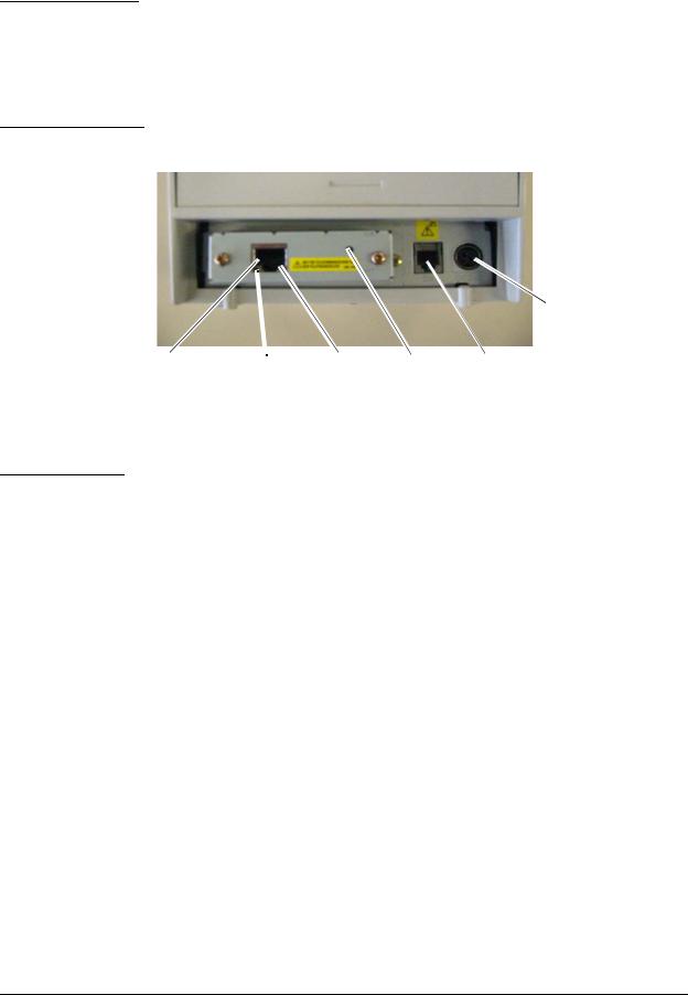
2.3Part Names
Power supply connector of the printer
10BASE-T/100BASE-TX LED (green) LED (yellow) |
Switch |
Drawer kick-out |
Ethernet interface |
|
connector of the printer |
connector |
|
|
Note: This photograph shows the TM-T88III printer with the UB-E02 installed.
2.4 Functions
The switch and LEDs of the UB-E02 provide you with important information on operation and status of the UB-E02.
2.4.1 Switch
Type: Non-locking push switch
You can do the following with the switch.
Setting initialization
All the parameters of internal settings for the UB-E02 can be set to the factory default values. See “Initializing UB-E02” on page 7 of this chapter for more details.
Status sheet printing
The internal setting parameters of the UB-E02 can be printed. See “UB-E02 Status Sheet Printing” on page 7 of this chapter for more details.
2.4.2LEDs
The UB-E02 has two LEDs.
The green LED is on when the Ethernet link is established.
The yellow LED is on when the printer receiving data.
2-2 Installation |
Rev. A |

UB-E02 Technical Reference Guide
2.5 UB-E02 Installation
 CAUTION:
Before installing the UB-E02, be sure to set the DIP switches or Memory switches as shown in the table below. For other models, please ask your dealer.
Model |
Setting |
|
|
TM-U200 Series |
DIP SW 2-8: ON |
|
|
TM-U210 Series |
DIP SW 2-8: ON |
|
|
TM-U220 Series (STD) *1 |
DIP SW2-8: ON |
|
|
TM-U220 Series (US) *1 |
DIP SW2-4: ON |
|
|
TM-U230 Series |
DIP SW 2-4: ON |
|
|
TM-U325 Series |
DIP SW 2-8: ON |
|
|
TM-U590 Series |
DIP SW 2-8: ON |
|
|
TM-U675 Series |
DIP SW 2-8: ON |
|
|
TM-T88/T88II/T88III |
DIP SW 2-8: ON |
|
|
TM-T90 |
MSW 1-8: ON |
|
|
TM-H5000/H5000II |
DIP SW 2-8: ON |
|
|
TM-H6000/H6000II |
DIP SW 2-8: ON |
|
|
TM-J7000/J7100 |
MSW 1-8: ON |
|
|
TM-J7500/J7600 |
MSW 1-8: ON |
|
|
TM-J2000/J2100 |
MSW 1-8: ON |
|
|
TM-L90 |
MSW 1-8: ON |
|
|
*1 TM-U220 has two DIP switch pattern. See TM-U220 Technical Reference Guide for detail.
Be sure to disconnect the power supply of the printer (in addition to turning off the power switch) .Even when the power switch is turned off, some of the internal circuit board has electricity. If you install or remove the UB-E02 with the power supply connected, the UB-E02 and the printer may be damaged.
1.Be sure that the power for the printer and host computer is turned off.
2.Install the UB-E02 in the printer.
If an interface circuit board is already installed, remove it and install the UB-E02.
Rev. A |
Installation 2-3 |

remove screw
 remove screw
3.Tighten the screws.
If you have removed an interface circuit board that was already installed, fix the UB-E02 using the removed screws.
4.Plug the twist pair cable into the 10BASE-T/100BASE-TX Ethernet connector of the UB-E02 until it clicks.
 CAUTION:
Be sure not to connect a telephone line, display module connector, or drawer kick-out connector cable to the 10BASE-T/100BASE-TX Ethernet connector of the UB-E02.
The display module connector on the TM printer cannot be used when the UB-E02 is installed.
5.Connect the power unit to the printer.
6.Turn on the printer power.
2-4 Installation |
Rev. A |
UB-E02 Technical Reference Guide
Note:
When initializing the UB-E02 by turning off the power and then turning it back on or by resetting the printer, there is a waiting time until the network starts operating. During this time, all the communicating functions of the network do not work.
The waiting time is:
When the IP address setting is Manual (Fixed): When the IP address setting is Auto:
approximately 6 seconds approximately 13 seconds
(It can be longer, depending on the reply time of the host.)
Rev. A |
Installation 2-5 |
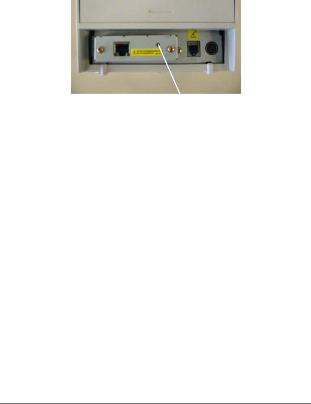
7.Print a status sheet to check whether the UB-E02 is installed correctly by holding the switch down for more than 3 seconds when the printer is ready for printing. The version of the UB-E02 and its settings are printed. See “UB-E02 Status Sheet Printing” on page 7 of this chapter.
Switch
2-6 Installation |
Rev. A |

UB-E02 Technical Reference Guide
2.6 Initializing UB-E02
All the parameters of internal settings for the UB-E02 can be set to the factory default values. Follow the steps below:
1.Turn off the printer power. Be sure to confirm that the LED lights are off.
2.Turn on the printer power while pressing the switch of the UB-E02 and hold the switch until the factory default values are printed.
3.After "Resetting to Factory Default!" is printed, release the switch.
4.Initialization takes approximately 30 seconds. Do not turn off the printer power during the initialization.
5.When the initialization is finished, the status sheet is printed. The following are printed on the status sheet.
•TCP/IP settings
•SNMP settings
•MAC address and version of UB-E02
•Other status items of UB-E02
 CAUTION:
Do not turn off the printer power until the status sheet is printed out.
2.7 UB-E02 Status Sheet Printing
The internal setting parameters of the UB-E02 can be printed. Follow the steps below:
1.Confirm that the printer power is on and the printer is ready for printing.
2.Press the switch of the UB-E02 and hold the switch more than 3 seconds.
3.After the status sheet printing starts, release the switch.
Rev. A |
Installation 2-7 |

2.8 FAQ
2.8.1 Q1. The printer does not operate correctly. ("Serial interface" is printed by the self test for the printer.)
2.8.1.1 A1. For TM-T90, TM-L90, TM-J2000, TM-J2100, TM-J7000, TM-J7100, TM-J7500, and TM-J7600, set the #25 pin reset signal of the Memory switch set to disabled. For other models, use the printer with the #31 pin reset signal of the DIP switch for parallel interface enabled.
Model |
Setting |
|
|
TM-U200 Series |
DIP SW 2-8: ON |
|
|
TM-U210 Series |
DIP SW 2-8: ON |
|
|
TM-U220 Series (STD) *1 |
DIP SW2-8: ON |
|
|
TM-U220 Series (US) *1 |
DIP SW2-4: ON |
|
|
TM-U230 Series |
DIP SW 2-4: ON |
|
|
TM-U325 Series |
DIP SW 2-8: ON |
|
|
TM-U590 Series |
DIP SW 2-8: ON |
|
|
TM-U675 Series |
DIP SW 2-8: ON |
|
|
TM-T88/T88II/T88III |
DIP SW 2-8: ON |
|
|
TM-T90 |
MSW 1-8: ON |
|
|
TM-H5000/H5000II |
DIP SW 2-8: ON |
|
|
TM-H6000/H6000II |
DIP SW 2-8: ON |
|
|
TM-J7000/J7100 |
MSW 1-8: ON |
|
|
TM-J7500/J7600 |
MSW 1-8: ON |
|
|
TM-J2000/J2100 |
MSW 1-8: ON |
|
|
TM-L90 |
MSW 1-8: ON |
|
|
*1 TM-U220 has two DIP switch pattern. See TM-U220 Technical Reference Guide for detail.
2.8.2 Q2. The self test does not operate correctly.
2.8.2.1 A2. Turn on the printer power while pressing the FEED button and hold the Feed button until printing starts to perform the self test for the printer with the UB-E02. Printing starts in approximately 6 seconds when the IP address is fixed or approximately 13 seconds when the IP address is acquired by auto setting. (It can be longer, depending on the reply time of the host.)
2.8.3 Q3. Starting up the printer takes a long time.
2-8 Installation |
Rev. A |

UB-E02 Technical Reference Guide
2.8.3.1 A3. When the auto setting is set for IP address acquisition without a DHCP server, starting up the printer takes about one minute. During this time, the self test for the printer is not performed. Set the manual setting for IP address acquisition where the DHCP server is not available.
Rev. A |
Installation 2-9 |

2-10 Installation |
Rev. A |
Loading...