


TM200 Service Manual
Service manual
TM200
Rev. No. : V. 1.10

|
|
|
TM200 Service Manual |
|
Contents |
|
|
|
|
1 Features and General Description ....................................................... |
- 1 - |
|||
|
1.1 |
Printer Parts .............................................................................. |
- 1 - |
|
|
1.2 |
Major Component Specifications............................................... |
- 6 - |
|
|
1.3 |
Connectors................................................................................ |
- 6 - |
|
|
1.4 |
Interfaces .................................................................................. |
- 7 - |
|
|
1.5 |
Buttons, Switches, and Panel Lights ......................................... |
- 9 - |
|
|
1.6 |
Self-test................................................................................... |
- 14 - |
|
|
1.7 |
Hexadecimal Dump................................................................. |
- 15 - |
|
|
1.8 |
Paper Sensors ........................................................................ |
- 16 - |
|
|
1.9 |
Standard Accessories.............................................................. |
- 16 - |
|
|
1.10 |
Options.................................................................................... |
- 17 - |
|
|
1.11 |
Consumables .......................................................................... |
- 17 - |
|
|
1.12 |
External Power Supply Specifications..................................... |
- 17 - |
|
2 |
Mechanisms and Operation ............................................................... |
- 19 - |
||
|
2.1 |
Component Connections Diagram .......................................... |
- 19 - |
|
|
2.2 |
TM200 Printer Mechanism ...................................................... |
- 19 - |
|
|
2.3 |
Main Circuit Board Unit ........................................................... |
- 21 - |
|
|
2.4 |
I/F Circuit Board Assembly...................................................... |
- 24 - |
|
|
2.5 |
Switch Circuit Board Assembly ............................................... |
- 24 - |
|
3 Handling, Maintenance, and Repairs................................................. |
- 25 - |
|||
|
3.1 |
Handling.................................................................................. |
- 25 - |
|
|
3.2 |
Problem Solving...................................................................... |
- 28 - |
|
|
3.3 |
Clearing Paper Jams............................................................... |
- 29 - |
|
|
3.4 |
Inspection and Maintenance ................................................... |
- 30 - |
|
4 |
Troubleshooting ................................................................................. |
- 32 - |
||
|
4.1 |
Symptoms and Solutions ........................................................ |
- 31 - |
|
|
4.2 |
Error Types and Processing.................................................... |
- 33 - |
|
5 |
Disassembly, Assembly, and Adjustment ........................................... |
- 35 - |
||
|
5.1 |
Before Starting disassembly, assembly, and adjustment......... |
- 35 - |
|
|
5.2 |
Using this Manual.................................................................... |
- 35 - |
|
|
5.3 |
TM200 Disassembly, Assembly, and Adjustment .................... |
- 36 - |
|
|
|
Door sensor block……………………………………………………- 37 - |
||
|
|
Front sensor and paper sensor block………………………….……- 39 - |
||
|
|
Autocutter module…………..........…………………………………- 42 - |
||
|
|
Thermal head module…............……………………………………- 44 - |
||
|
|
Main circuit board….…………………………………………………- 47 - |
||
Appendix A |
Interface………………………………………………………- 50 - |
|||
Appendix B |
Exploded Diagram ......................................................... |
- 52 - |
||
Appendix C Panel lights and indicators ........................................... |
- 53 - |
|||
Appendix D Parts number list ........................................................... |
- 55 - |
|||

TM200 Service Manual
1Features and General Description
1.1 Printer Parts
Printer cover
Control Panel
Cutter cover
Cover open button
Figure 1-1 TM200 appearance
- 1 -

TM200 Service Manual
Printing Specifications
Printing method: |
Thermal line printing |
|
|
Dot density: |
203 dpi x 203 dpi (8 dot/mm) |
|
|
|
|
|
|
Printing direction: |
Unidirectional with friction feed |
|
|
|
|
|
|
Printing width: |
72mm (2.83”), 576 dot positions |
|
|
|
|
|
|
Characters per line (default): |
48 (Font A) |
|
|
|
64 (Font B) |
|
|
Character spacing (default): |
0.28 mm (0.1”) (2 dots) (Font A) |
|
|
|
0.28mm (.01”) (2 dots) (Font B) |
|
|
|
Programmable by control command. |
|
|
|
|
|
|
Printing speed |
180 mm / sec (approxi. 7.1” / sec) |
|
|
|
60 lines / sec (computed value for 3.18mm (1/8”) feed) |
||
|
28.4 lines / sec maximum |
|
F), density level 2) |
|
(4.23 mm (1/6”) feed, at 24V, 28 C (82 |
|
|
|
|
|
|
Paper feeding speed: |
Approximately 180 mm / sec (7.0”/sec) continuous paper |
||
|
feeding |
|
|
|
|
|
|
Receive Buffer Size |
96K Bytes |
|
|
Number of characters: |
Alphanumeric characters: 95 |
|
|
|
International characters: 32 |
|
|
|
Extended graphics: 128x7pages |
|
|
|
(including one space page) |
|
|
|
Traditional/ Simplified Chinese, Japanese, Kanji characters |
||
Character structure: |
Font A: 12 x 24 (including 2-dot spacing horizontally) |
||
|
Font B: 9 x 17 (including 2-dot spacing horizontally) |
||
|
Kanji: 24 x 24 |
|
|
|
Default font: Font A |
|
|
|
|
|
|
Notes:
Printing speed may be slower depending on the data transmission speed and the combination of control commands.
There may be variations in printing speed. To prevent this for logo printing, using a downloaded bit image is recommended.
Low transmission speed may cause intermittent printing. It is recommended to transmit data to the printer as quickly as possible.
Character size:
|
Standard |
|
Double-height |
Double-width |
Double-weight/ |
||||
|
|
|
|
|
Double-height |
|
|||
|
|
|
|
|
|
|
|
||
|
W x H (mm) CPL |
W x H (mm) |
CPL |
W x H (mm) |
CPL |
W x H (mm) |
CPL |
||
Font A |
1.23 x 2.97 |
48 |
1.23 x 5.92 |
48 |
2.47 x 2.97 |
24 |
2.47 x5.92 |
24 |
|
12 x 24 |
(.05” x .11”) |
(.05” x .24”) |
(.10” x .11”) |
(.10” x .24”) |
|||||
|
|
|
|
||||||
B |
0.87 x 2.10 |
64 |
0.87 x 4.20 |
64 |
1.73 x 2.10 |
32 |
1.73 x 4.20 |
32 |
|
9 x 17 |
(.035” x .08”) |
(.035” x .17”) |
(.07” x .08”) |
(.07” x .17”) |
|||||
|
|
|
|
||||||
Kanji |
2.97 x 2.97 |
24 |
2.97 x 5.92 |
24 |
5.92 x 2.97 |
12 |
5.92 x 5.92 |
12 |
|
24 x 24 |
(.11” x .11”) |
(.11” x .24”) |
(.24” x .11”) |
(.24” x .24”) |
|||||
|
|
|
|
||||||
*CPL = Characters Per Line
*Space between characters is not included
*Characters can be scaled up to 64 times as large as the standard sizes.
- 2 -

Autocutter |
TM200 Service Manual |
|
|
Partial cut: |
Cutting with one point center uncut |
|
(selectable by ESC I or GS V) |
Full cut: |
Cutting without uncut (selectable by ESC i ) |
Note:
To prevent dot displacement, after cutting, paper must be fed approximately 1 mm (14/360 or 0.04 inch) or more before printing.
Paper Specifications
Paper type: |
Specified thermal roll paper |
Form: |
Paper roll |
Paper width: |
79.5 ±0.5 mm (3.13" ± 0.02") |
Paper roll size: |
|
Roll diameter: |
Maximum 83 mm (3.27") |
Take-up paper roll width: |
80 + 0.5 / -1.0 mm |
Paper roll diameter: |
Inside: 12 mm (0.47") |
|
Outside: 18 mm (0.71") |
CAUTION:
Paper must not be pasted to the paper roll.
Printable Area
Paper roll |
The printable area of a paper with width of 79.5 ± 0.5 mm |
|
(3.13" ± 0.02") is 72.2 ± 0.2 mm (2.84" ± 0.008") (576 dots) |
Internal Buffer |
|
Receive buffer selectable as 2KB or 96KB using the DIP switch.
Non-volatile bit image buffer: 128KB
Electrical Specifications
Supply voltage: |
+24 VDC ± 7% Current consumption (at 24V, normal |
|
temperature) |
High-speed mode: |
Mean: Approximately 1.8A |
|
(Font A alphanumeric character printing for all columns) |
|
Peak: Approximately 7.8A |
Standby: |
Mean: Approximately 0.2A |
Note :
Maximum 1A for drawer kick-out driving.
- 3 -

TM200 Service Manual
EMI and Safety Standards Applied
These standards are only valid for products which bear a mark or statement on the main unit.
Europe: |
CE marking: Directive: 89/336/EEC |
|
|
|
EN55022:1998 Class A |
|
|
EN6100-3-3:1995+A1:2001 |
|
|
EN55024:1998, including |
|
|
IEC61000-4-2, IEC61000-4-3, IEC61000-4-4, IEC61000-4-5, |
|
|
IEC61000-4-6, IEC61000-4-8, |
|
Safety standards: |
EN60950 |
North America: |
EMI: |
FCC Class A |
|
Safety standards: |
UL1950/CSA C22.2 No.950 |
Oceania: |
EMI: |
AS/NZS3548 |
Conditions of acceptability
1.This component has been judged on the basis of the required spacing in the Standard for Information Technology Equipment, including Electrical Business Equipment, UL 1950 and CSA22.2 No. 950. sub-clause 2.9, which would cover the component itself if submitted for Listing.
2.The terminals and connectors have not been evaluated for field wiring.
Reliability
Life: |
Mechanism: |
15,000,000 lines |
|
Thermal head: |
100 million pulses, 50 Km |
|
Autocutter: |
1,200,000 cuts |
|
|
(End of life is defined to have been reached |
|
|
when it reaches the beginning of the wear out |
|
|
period.) |
MTBF: |
|
360,000 hours |
|
|
(Failure is defined as a random failure |
|
|
occurring during the time of the random |
|
|
failure period.) |
MCBF: |
|
52,000,000 lines |
|
|
(This is an average failure interval based on |
|
|
failures relating to wear out and random |
|
|
failures up to the life of 15 million lines.) |
External Dimensions and Weight: |
|
|
|
Height: |
Approximately 138.7 mm (5.46") |
|
Width: |
Approximately 146.5 mm (5.77") |
|
Depth: |
Approximately 195 mm (7.68") |
|
Weight: |
Approximately 1.4 kg (3.08 lb) |
|
|
(except for the paper roll) |
- 4 -

TM200 Service Manual
Environmental Conditions
Temperature: |
|
|
Operating: |
5 to 45 (41 to 113 ) |
|
Storage: |
–10 to 50 (14 to 122 ) (except for paper) |
|
Humidity: |
|
|
Operating: |
10 to 90% |
RH |
Storage: |
10 to 90% |
RH (except for paper) |
- 5 -
TM200 Service Manual
1.2Major Component Specifications
TM200 Printer Mechanism
Paper Feed Motor
Type: |
4-phase, 48-polarity, PM-type stepping motor |
Drive voltage: |
24 VDC ± 10% |
Winding resistance: |
11.5 ± 10% at 25° C (77° F), per phase |
Print Head Unit |
576 dots |
Dot number: |
|
Dot density: |
0.125 mm/dot (203 DPI) |
Resistance: |
Average 600 ± 4.6% |
Paper-end Sensor |
Reflection type photo sensor |
Paper Roll Near-end Sensor |
Reflection type photo sensor |
Autocutter Unit |
DC brush motor |
Type: |
|
Cutter motor voltage: |
24 VDC ± 7% |
Current consumption: |
800 mA peak (at starting, low temperature) |
|
70 mA average (room temperature) |
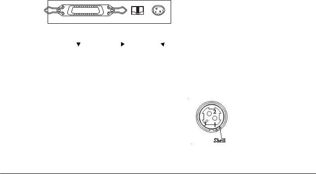
1.3Connectors
Interface Drawer kick-out Power supply
Power Supply Connector
This connector is used to connect the printer to an external power source.
Pin number |
Signal name |
1 |
+24 VDC |
2 |
GND |
3 |
NC |
Shell |
Frame GND |
Figure 1-2 Power supply connector
- 6 -
TM200 Service Manual
Drawer Kick-out Connector
The pulse specified by ESC p is output to this connector. For the serial interface model, the host can confirm the status of the input signal by using the DLE EOT, GS r, or GS a (ASB) commands.
Drawer kick-out connector pin assignments |
|
|
Pin Number |
Signal Name |
Direction |
1 |
Frame GND |
— |
2 |
Drawer kick-out drive signal 1 |
Output |
3 |
Drawer open/close signal |
Input |
4 |
+24 V |
— |
5 |
Drawer kick-out drive signal 2 |
Output |
6 |
Signal GND |
— |
+24 V is always output through pin 4 during power on.
CAUTION:
Pin 4 must be used only for the drawer.
Figure 1-3 Drawer kick-out connector
Drawer kick-out drive signal |
|
Output signal: |
Output voltage: Approximately 24 V |
|
Output current: 1A or less |
CAUTION:
To avoid an over current, the resistance of the drawer kick-out solenoid must be 24 or more.
1.4 Interfaces
RS-232 serial interface
Specifications: |
|
Data transmission: |
Serial |
Synchronization: |
Asynchronous |
Handshaking: |
DTR/DSR or XON/XOFF control |
Baud rate: |
4800, 9600, 19200, 38400 bps |
Data word length: |
7 or 8 bits |
Parity: |
None, even, odd |
Stop bits: |
1 or more |
Connector (printer side): |
Female DSUB-25 pin connector |
- 7 -

TM200 Service Manual
Note:
The handshaking, data word length, baud rate, and parity depend on the DIP switch settings. Data transmitted from the printer has 1 stop bit (fixed)
Switching between online and offline
The printer does not have an online/offline switch. The printer goes offline:
When the cover is open
When an error has occurred
When the printer stops printing due to a paper-end(in cases when an empty paper supply is detected by either paper roll end detector or the paper roll nearend detector with a printing halt feature using
ESC c 4)
Interface connector terminal assignments and signal functions are described in the table below.
TM200 serial printer status and signals:
Pin number |
Signal name |
Signal |
Function |
|
|
direction |
|
|
|
|
|
|
|
|
|
1 |
FG |
--- |
Frame ground |
2 |
TXD |
Output |
Transmit data |
3 |
RXD |
Input |
Receive data |
4 |
RTS |
Output |
Same as DTR signal (Pin 20) |
6 |
DSR |
Input |
This signal indicates whether the host computer |
|
|
|
can receive data. |
|
|
|
|
|
|
|
SPACE indicates that the host computer can |
|
|
|
receive data, and MARK indicates that the host |
|
|
|
computer cannot receive data. |
|
|
|
|
|
|
|
When DTR/DSR control is selected, the printer |
|
|
|
transmits data after confirming this signal (except |
|
|
|
when transmitting data by DLE EOT, and GS a). |
|
|
|
|
|
|
|
When XON/XOFF control is selected, the printer |
|
|
|
does not check this signal. |
|
|
|
|
7 |
SG |
--- |
Signal ground |
- 8 -
TM200 Service Manual
Serial interface connection example.
Host |
|
Printer |
(DTE ex. 8251) |
|
|
TXD –––––––––––––––– |
RXD |
|
DSR –––––––––––––––– |
DTR |
|
CTS –––––––––––––––– |
RTS |
|
RXD –––––––––––––––– |
TXD |
|
DTR –––––––––––––––– |
DSR |
|
FG |
–––––––––––––––– |
FG |
SG |
–––––––––––––––– |
SG |
Note:
Set the handshaking so that the transmitted data can be received.
Transmit data to the printer after turning on the power and initializing the printer.
1.5Buttons, Switches, and Panel Lights
Power Switch
Type: |
Rocker switch |
Function: |
The power switch turns the power on or off. |
Note:
Turn on the power only after connecting the power supply.
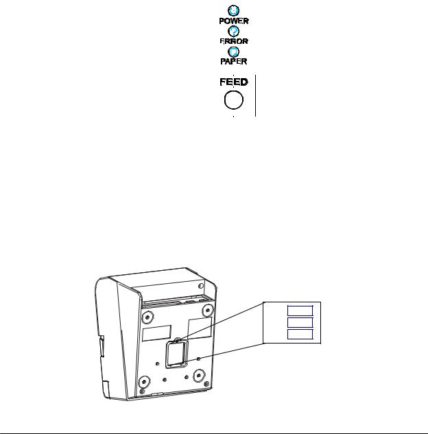
Panel Button
FEED button: |
If you push this button once and release it, the printer |
|
feeds paper for one line based on the line spacing set by |
|
ESC 2 and ESC 3. If you hold on the button, the printer |
|
will feed paper continuously. |
|
Paper feeding using the FEED button cannot |
|
be performed when the printer cover is open. |
Note:
The ESC c 5 command enables or disables the panel button. When the command disabled the button, it will not function.
- 9 -
TM200 Service Manual
Panel lights
POWER: |
Green |
|
|
|
|
Power is on. |
||||
|
On: |
|
|
|
|
|||||
|
Off: |
|
|
|
|
Power is not on. |
||||
ERROR: |
Red |
|
|
|
|
Offline (except during paper feeding |
||||
|
On: |
|
|
|
|
|||||
|
|
|
|
|
|
using the FEED button and the error |
||||
|
Off: |
|
|
|
|
state) |
||||
|
|
|
|
|
Normal condition. |
|||||
|
Blinking: |
|
|
|
|
Error |
||||
PAPER: |
Red |
|
|
|
|
The paper roll near end is detected. |
||||
|
On: |
|
|
|
|
|||||
|
Off: |
|
|
|
|
Paper is loaded (normal condition) |
||||
|
Blinking |
|
|
|
|
Self-test standby state |
||||
|
|
|
|
|
|
|
|
|
|
|
|
|
|
|
|
|
|
|
|
|
|
|
|
|
|
|
|
|
|
|
|
|
|
|
|
|
|
|
|
|
|
|
|
|
|
|
|
|
|
|
|
|
|
|
|
|
|
|
|
|
|
|
|
|
|
|
|
|
|
|
|
|
|
|
|
|
|
|
|
|
|
|
|
|
|
|
|
|
|
|
|
|
|
|
|
|
|
|
|
|
|
|
|
|
|
|
|
|
|
|
|
|
|
|
|
|
|
|
|
|
|
|
|
|
|
|
|
|
|
|
|
|
|
|
|
|
|
|
|
|
|
|
|
|
|
|
|
|
|
|
|
|
|
|
|
|
|
|
|
|
|
|
|
|
Figure 1-4 Panel button and indicators
Note:
The panel lights can tell you a lot of information about the situation of the printer, please refer to Appendix C for details.
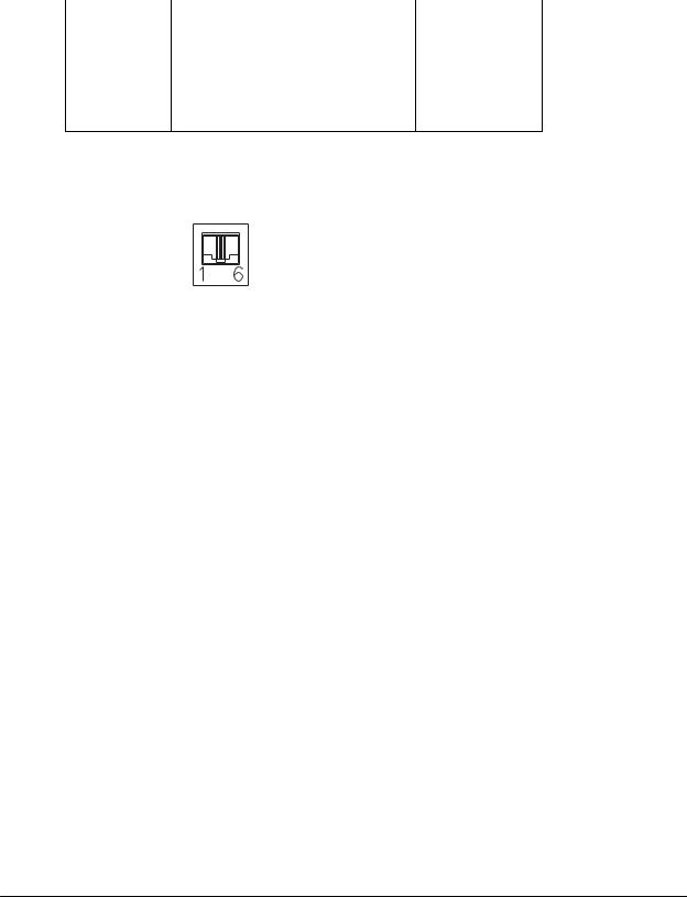
DIP Switches
Serial interface model
The DIP switches are located at the bottom of the case.
SW3
SW2
SW1
Figure 1-5 DIP switches
- 10 -

|
|
|
|
TM200 Service Manual |
|
DIP switch 1 |
|
|
|
|
|
DIP switch |
Function |
ON |
|
OFF |
|
|
|
|
|
|
|
1-1 |
Print emulation |
TM200(default) |
|
EPSON Emulation |
|
|
|
|
|
|
|
1-2 |
Paper near end sensor |
Vertical |
|
Horizontal(default) |
|
|
|
|
|
|
|
1-3 |
Selects print density |
Refer to the table as below |
|||
|
|||||
1-4 |
|||||
|
|
|
|
||
|
|
|
|
|
|
1-5 |
Cutter setting |
Disable |
|
Enable(default) |
|
|
|
|
|
||
1-6 |
Stop bit |
Fixed to OFF (1 bit) |
|||
|
|
|
|
|
|
1-7 |
Cutter mode |
Full |
|
Partial(default) |
|
|
|
|
|
|
|
1-8 |
Reserved: do not change |
|
Fixed to OFF |
||
settings |
|
||||
|
|
|
|
||
Note:
TM200 accept ESC/POS command. Dip 1-1 for different printing format, ON(TM200) for 48 characters per line, OFF(EPSON Emulation) for 42 Characters per line.
Print Density Selection
|
Print Density |
SW 1-3 |
SW 1-4 |
|
|
|
|
1 |
Low power consumption |
ON |
ON |
|
mode |
||
|
|
|
|
2 |
(Normal) |
OFF(default) |
OFF(default) |
|
|
|
|
3 |
|
ON |
OFF |
|
|
|
|
4 |
(Dark) |
OFF |
ON |
|
|
|
|
DIP switch 2
DIP switch |
Function |
ON |
|
OFF |
|
|
|
|
|
|
|
2-1 |
Reserved |
|
Reserved |
||
|
|
|
|
|
|
2-2 |
Receive buffer capacity |
2K bytes |
|
96K bytes(default) |
|
|
|
|
|
|
|
2-3 |
Handshaking |
|
Fixed to OFF |
||
|
|
|
|||
2-4 |
Data word length |
Fixed to OFF (8 bits) |
|||
|
|
|
|||
2-5 |
Parity check |
Fixed to OFF (None) |
|||
|
|
|
|
|
|
2-6 |
Parity selection |
Even |
|
Odd(default) |
|
|
|
|
|
|
|
2-7 |
Transmission speed (See the table below) |
||||
|
|||||
2-8 |
|||||
|
|
|
|
||
|
|
|
|
|
|
- 11 -

TM200 Service Manual
Transmission Speed |
|
|
|
|
|
|
|||
Transmission Speed |
|
SW 2-7 |
|
SW 2-8 |
|
||||
(BPS) – bits per second |
|
|
|
||||||
|
|
|
|
|
|
|
|||
|
4800 |
|
|
|
OFF |
|
ON |
|
|
|
|
|
|
|
|
|
|
|
|
|
9600 |
|
|
|
ON |
|
OFF |
|
|
|
|
|
|
|
|
|
|
|
|
|
19200 |
|
|
OFF(default) |
|
OFF(default) |
|
||
|
|
|
|
|
|
|
|
|
|
|
38400 |
|
|
|
ON |
|
ON |
|
|
|
|
|
|
|
|
|
|
|
|
DIP switch 3 |
|
|
|
|
|
|
|
|
|
|
|
|
|
|
|
|
|
|
|
DIP switch |
|
Function |
|
|
|
ON |
|
OFF |
|
|
|
|
|
|
|
|
|||
3-1 |
Buzzer1 setting |
|
|
Disable |
|
Enable(default) |
|||
|
|
|
|
|
|
|
|||
3-2 |
Buzzer 2 setting |
|
|
Disable |
|
Enable(default) |
|||
|
|
|
|
|
|
|
|
||
3-3 ~ 3-8 |
|
Undefined |
|
|
- |
|
- |
||
|
|
|
|
|
|
|
|
|
|
Note:
In order to connect Serial port, the host setting should be set as:
Data bits |
8 |
bits |
|
|
|
Parity check |
None |
|
|
|
|
Stop bits |
1 |
bit |
|
|
|
Flow control (suggest to set for None) |
None |
|
|
|
|
- 12 -

TM200 Service Manual
Parallel interface model
DIP switch 1
DIP switch |
Function |
ON |
|
OFF |
|
|
|
|
|
|
|
1-1 |
Print emulation |
TM200(default) |
|
EPSON Emulation |
|
|
|
|
|
|
|
1-2 |
Paper near end sensor |
Vertical |
|
Horizontal(default) |
|
|
|
|
|
|
|
1-3 |
Selects print density |
Refer to page as below |
|||
|
|||||
1-4 |
|||||
|
|
|
|
||
|
|
|
|
|
|
1-5 |
Cutter setting |
Disable |
|
Enable(default) |
|
|
|
|
|
|
|
1-6 |
Parallel port supports |
EPP |
|
SPP/EPP(default) |
|
|
|
|
|
|
|
1-7 |
Cutter mode |
Full |
|
Partial(default) |
|
|
|
|
|
|
|
1-8 |
Reserved: do not change |
|
Fixed to OFF |
||
settings |
|
||||
|
|
|
|
||
Note:
TM200 accept ESC/POS command. Dip 1-1 for different printing format, ON (TM200) for 48 characters per line, OFF (EPSON Emulation) for 42 Characters per line.
Print Density Selection
|
Print Density |
SW 1-3 |
SW 1-4 |
|
|
|
|
1 Low power consumption mode |
ON |
ON |
|
|
|
|
|
2 |
(Normal) |
OFF(default) |
OFF(default) |
|
|
|
|
3 |
|
ON |
OFF |
|
|
|
|
4 |
(Dark) |
OFF |
ON |
|
|
|
|
DIP switch 2
DIP switch |
Function |
ON |
OFF |
|
|
|
|
2-1 |
Auto line feed |
Always enabled |
Always disabled(default) |
|
|
|
|
2-2 |
Receive buffer capacity |
2K bytes |
96K bytes(default) |
|
|
|
|
2-3 ~ 2-8 |
Undefined |
- |
- |
|
|
|
|
DIP switch 3
DIP switch |
Function |
ON |
OFF |
|
|
|
|
3-1 |
Buzzer1 setting |
Disable |
Enable(default) |
|
|
|
|
3-2 |
Buzzer 2 setting |
Disable |
Enable(default) |
|
|
|
|
3-3 ~ 3-8 |
Undefined |
- |
- |
|
|
|
|
- 13 -

TM200 Service Manual
1.6Self-test
The printer has a self-test function that checks the following:
Control circuit functions
Printer mechanisms
Print quality
Control software version
DIP switch settings.
NOTE:
This test is independent of any other equipment or software.
Running the self test
1.Make sure the printer is turned off and the printer cover is closed properly.
2.Make sure a paper roll has been installed properly.
3.While holding down the FEED button, turn on the printer using the switch on the front of the printer to begin the self test. The self test prints the printer settings, and then prints the following, cuts the paper, and pauses.
If you want to continue SELF-TEST
Please press the FEED button
4.Press the FEED button to continue printing. The printer prints a pattern using the built-in character set.
5.The self test automatically ends and cuts the paper after printing the following.
*** completed ***
Please re-start to exit SELF-TEST
- 14 -

TM200 Service Manual
1.7Hexadecimal Dump
Hexadecimal Dump Function
This function prints the data transmitted from the host computer in hexadecimal numbers and in their corresponding characters.
Performing a Hexadecimal Dump
To use the hex dump feature, follow these steps:
1.After you make sure that the printer is off, open the cover.
2.Hold down the FEED button while you turn on the printer.
3.Close the cover.
4.Run any software program that sends data to the printer. The printer prints “Hexadecimal Dump” and then all the codes it receives in a two-column format. The first column contains the hexadecimal codes and the second column gives the ASCII characters that correspond to the codes.
Hexadecimal Dump |
|
|
1B 21 00 1B 26 02 40 |
40 |
← ! ← & ☻ @ @ |
1B 25 01 1B 63 34 00 |
1B |
←%☺← c 4 ← |
41 42 43 44 45 43 47 48 |
ABCDEFGH |
|
5.Close the cover and turn off the printer or reset it to turn off the hex dump mode. (or to terminate hex dump, press FEED button three times, and when you see
*** completed ***
the hex dump mode was turned off.
Note:
Insufficient print data to fill the last line can be printed by setting the printer offline.
Ending hexadecimal dumping
Hexadecimal dumping ends by turning the power off or resetting the printer via the interface after printing has finished.
- 15 -

TM200 Service Manual
1.8Paper Sensors
The printer has 2 paper sensors as follows:
Paper roll near-end sensor
The sensor detects a near-end of a paper roll.
When the paper roll diameter becomes sufficiently small, the sensor detects a near-end of the paper roll and the PAPER indicator lights on.
Paper roll end sensor
This sensor detects whether paper is present or not.
When the sensor detects a paper-end, the printer stops printing.
Note:
After installing new paper roll, close the printer cover; then the printer restarts printing.
Cover Open Button
When the cover open button (located to the right of the cover) is pressed, the printer cover is opened. When the cover is closed, the cover open button is latched.
Note:
Be sure to use the cover open button to open the printer cover. Do not open the cover during printing.
Do not open the cover during the autocutter is operating; otherwise the mechanism may be damaged.
Cover Open Sensor
The cover open sensor monitors the printer cover. When the sensor detects a cover open during printing, the ERROR light blinks and the printer stops printing. The printer recovers when the cover is closed.
When the sensor detects a cover open while the printer is in the standby status, the printer goes offline. The printer recovers when the cover is closed.
Note:
Whether the cover is open or not does not affect the status reported by the paper roll end sensor.
1.9Standard Accessories
Sample paper roll x 1 roll
User's Manual
Exclusive external power supply unit and power cord
Disc x 1
Communication printer cable
- 16 -
 Loading...