


DYNEX MAS3693CC, MAS3693CB, MAS3691NS, MAS3691NE, MAS3691ND Datasheet
...MA3690/1/3
1553B Bus Controller/Remote Terminal
Replaces June 1999 version, DS3587-4.0 |
DS3587-5.0 January 2000 |
The MA3690/1 chip set has three modes of operation: remote terminal, bus controller, and passive monitor It has a dual bus capability, requires minimum support hardware / software and is implemented on a radiation hard, CMOS/SOS process. For applications requiring access to Terminal Flag, a 48-Pin DIL MA3693 is available as an alternative to the MA3690.
As a remote terminal, the MA3690/1 is fully compatible with Mil-Std-1553B. The chip set obtained SEAFAC approval in December 1987. All options and mode commands specified by the Mil Std are implemented Full and meaningful use is made of status word bits and a comprehensive bit word is provided.
A unique mechanism has been incorporated that allows the subsystem to declare illegal commands legal, and vice versa, before the chip set services the command. It should be noted that use of this mechanism is optional and that the system defaults to normal operation if the option is not required. The chip set is easily interfaced to subsystem memory and is sufficiently flexible to ensure compatibility with a wide range of microprocessors.
As a bus controller the MA3690/1 has the ability to initiate all types of 1553B transfer on either of the two buses An instruction word is set up by the subsystem, prior to transmission, which contains details of transfer type and bus selection. Four bits of the instruction word have been used to specify the conditions under which the chip set will generate a subsystem interrupt. The most significant bits of the instruction word have been used to specify the conditions under which the chip set will perform an automatic retry and the number of retries to be carried out (max. 3). At the end of each instruction execution cycle, the chip set writes a report word into the subsystem memory; the contents of which give the subsystem an indication of the degree of success of the transfer.
The bus controller may be used in either of two configurations, i.e. single shot or table driven.
In the single shot configuration, the controller is under direct control from the subsystem (processor). In table driven configuration, the controller is given greater autonomy to execute a table of instructions held in either ROM or RAM.
As a passive monitor, the chip set will monitor all bus activity and pass any associated information to the subsystem. As the name implies, in this mode of operation, the chip set is truly passive and will not reply to command instructions.
FEATURES
■Radiation Hard to 1MRads (Si)
■High SEU Immunity, Latch-Up Free
■CMOS-SOS Technology
■All Inputs and Outputs Fully TTL or CMOS Compatible
■Military Temperature Range -55 to +125°C
■Dual Bus Capability
■Minimal Subsystem Interface
■Powerful Bus Control Facility
■Complete Remote Terminal Protocol
■SEAFAC Approved
SIGNAL DESCRIPTIONS
All signals are TTL compatible unless stated otherwise. An ‘N’ at the end of the signal name denotes an active low signal.
SUPPLIES
VDD |
5 volts positive supply |
VSS |
Ground |
CLOCK INPUTS
CK12 12MHz clock
BUS INTERFACE LINES
PDIN0 Input
Positive threshold exceeded on bus 0.
NDIN0 Input
Negative threshold exceeded on bus 0.
TXEN0N Output
Transmit enable for driver on bus 0.
PDOUT0N Output
Positive Manchester data for driver on bus 0.
1/41
MA3690/1/3
NDOUT0N Output
Negative Manchester data for driver on bus 0.
PDIN1 Input
Positive threshold exceeded on bus 1.
NDIN1 Input
Negative threshold exceeded on bus 1.
TXEN1N Output
Transmit enable for driver on bus 1.
PDOUT1N Output
Positive Manchester data for driver on bus 1.
NDOUT1N Output
Negative Manchester data for driver on bus 1.
SUBSYSTEM INTERFACE LINES
STROBEN Output
STROBE - Information transfer strobe pulse for words being transferred on the data highway.
BUFENN Output
BUFFER ENABLE - This line goes low to enable the data highway buffer between the terminal and the subsystem.
R/WN Output
READ/WRITE - This line indicates the direction of information transfer between the terminal and the subsystem. When low, information is being written from the terminal to the subsystem.
DTRQN Output
DATA TRANSFER REQUEST - This line goes low to request permission to transfer a non mode data word to or from the subsystem.
DTAKN Input
DATA TRANSFER ACKNOWLEDGE - This line should be driven low to grant permission to perform the requested data word transfer.
MDTN Output MODE DATA TRANSFER -
RT: This line goes low to indicate that the data word being transferred is assosiated with a mode command.
BC: When operating as a passive monitor this line goes low to indicate that a valid data word is on the data highway and should be written into the received data latch.
GBRN Output
GOOD BLOCK RECEIVED - When in RT mode this line will pulse low to inform the subsystem that the received non mode data words are valid and may be used.
ADENN Output
ADDRESS ENABLE - When in RT mode this line will go low as part of the reset routine to enable the terminal address on to the data highway.
SYNCN Output
SYNCHRONISE - This line will pulse low if a valid synchronise mode command without data is received and passes all validity checks.
STATENN Output
STATUS ENABLE -
RT: When low this line enables the contents of the subsystem status latch on to the data highway.
BC: When low this line enables the BC report word on to the data highway.
MDRN Output
MODE DATA RECEIVED - This line will pulse low to inform the subsystem that the received mode data is valid and may be used.
RXCMDN Output RECEIVED COMMAND -
RT: This line goes low to indicate that a valid command word for this RT is on the highway and should be written into the command word latch.
BC: When operating as a passive monitor this line goes low to indicate that a valid command / status word is on the data highway and should be written into the received status latch.
BUSYREQN / HALTREQN Input BUSY REQUEST / HALT REQUEST -
RT: This line should be driven low as a request for the terminal to set the busy bit and inhibit non mode data transfers to or from the subsystem.
BC: This line should be driven low as a request for the terminal to halt table execution and all subsystem access.
BUSYACKN / HALTEDN Output
BUSY ACKNOWLEDGE / HALTED -
RT: This line will go low to indicate that the subsystem has free access to the shared store.
BC: This line will go low to indicate that all terminal operation has been halted and hence the subsystem has free access to the shared store.
CODENN Output
CODE ENABLE - This line when low indicates that a word transfer between the terminal and either the Instruction Store or the Report Store is taking place.
C0 |
Output |
CODE 0 |
- This line is the least significant address line from |
the terminal to the Instruction and Report Stores. |
|
C1 |
Output |
CODE 1 |
- This line is the least significant but one address |
line from the terminal to the Instruction and Report Stores.
2/41
INCADRN Output
INCREMENT ADDRESS - This line pulses low to increment the external instruction addressing counter.
HSFN/IRQN Output
HANDSHAKE FAIL / INTERRUPT REQUEST
RT: This line pulses low to inform the subsystem that it has not responded to a data transfer request to take place. BC: This line pulses low to generate an interrupt to the BC subsystem processor.
INCMDN Output
IN COMMAND - When low this line indicates that the terminal is currently servicing a command word.
EOTN Output
END OF TRANSMISSION - When low this line indicates that the selected bus is quiet and hence available for use.
ABORTN Output
This line will pulse low to abort execution of the current command if an error is detected.
B0-B15 Input/Output
HIGHWAY LINES - 16 line bidirectional Output data highway. (B0 = LSB).
CLDN Inter-chip (CMOS)
COMMAND LOAD - When low this line indicates that the word on the data highway should be loaded into the transmitter for transmission with a command sync.
DLDN Inter-chip (CMOS)
DATA LOAD - When low this line indicates that the word on the data highway should be loaded into the transmitter for transmission with a data sync.
OBFN Inter-chip (CMOS)
OUTPUT BUFFER FULL - When low this line indicates that the transmitter output buffer is full and cannot be overwritten.
VALDRN Inter-chip (CMOS)
VALID DATA RECEIVED - When low this line indicates that a valid data word has been received and is on the data highway.
VALCRN Inter-chip (CMOS)
VALID COMMAND RECEIVED -
RT: When low this line indicates that a valid command word for this RT has been received.
BC: When low this line indicates that a valid word with a command sync has been received.
RT/BCN Input
REMOTE TERMINAL/BUS CONTROLLER - When high the terminal will function as an RT.When low the terminal will function as a bus controller.
CK4 Output 4MHz system clock.
MA3690/1/3
PUCN Input
POWER UP CLEAR - This line should be pulsed low following power-up.
RESETN Input/Output
RESET - This line when low, forces the internal circuitry to reset to the quiescent initialised state. This is a ‘TTL’ level input on both devices and an open-drain output on the MA3690. The subsystem should drive this line via an open drain/collector device with external pull up fitted.
RT0 / RT1 Inputs
REPLY TIMEOUT DECODE - These lines on the MA3690 allow four different timeout values to be used. On the MA3693, the RT1 signal is not available and is pulled down internally.
RT1 |
RT0 |
Timeout (us) |
|
|
|
0 |
0 |
16 |
0 |
1 |
22 |
1 |
0 |
44 |
1 |
1 |
108 |
|
|
|
Note: Under normal operation, option 00 should be used. (i.e. 16uS)
The measurement is taken between mid parity and mid sync - measured at PDIN/NDIN terminals.
TF Output
TERMINAL FLAG - This line is available only on the 64-pin MA3690 and on the MA3693 (where it replaces RT1). The line indicates the state of the Terminal Flag bit in the Status Word, and can be inhibited by the mode code Inhibit Terminal Flag. This is an active LOW signal.
TEST/SOT Inputs
These lines are for test purposes only and for normal chip set operation must both be tied low.
3/41
MA3690/1/3
OPERATION IN BUS CONTROL MODE
For this mode of operation the RT/BC pin must be held in the logic zero state. On power up the PUC or RESET line must be pulsed low for a minimum of 500ns causing the chip set to initialise and assume the halted state with the HALTED output low. To release the terminal from the halted state, the subsystem must drive the HALTREQ line through a low to high transition, at which time the HALTED line will go inactive.
When the HALTED line goes inactive,the terminal will address a four word deep Instruction Store as shown below, using the C0 and Cl outputs.
This first instruction after a Reset is a NOOP.
INSTRUCTION STORE
C1 |
C0 |
Word |
|
|
|
0 |
0 |
Instruction |
0 |
1 |
Receive Command |
1 |
0 |
Transmit Command |
1 |
1 |
Data Pointer |
|
|
|
The instruction word specifies the operation which the terminal is to carry out, and is formatted in the following way:
Instruction Word
Bit |
|
|
|
|
|
15.14. |
13.12.11. |
10.9.8.7. |
6.5. |
4.3. |
2.1.0. |
|
|
|
|
|
|
Retry |
Retry |
Interrupt |
Bus |
Functlon |
Message |
Count |
Condition |
Conditlon |
Select |
Code |
Code |
|
|
|
|
|
|
The significance of the instruction word bits are as follows:
Message Code
Code |
Transfer Type |
|
|
000 |
RT to BC |
001 |
BC to RT |
010 |
RT to RT, data to BC subsystem |
011 |
RT to RT, no data to BC subsystem |
100 |
Broadcast RT to BC, non data mode commands only |
101 |
Broadcast BC to RT |
110 |
Broadcast RT to RT, data to BC subsystem |
111 |
Broadcast RT to RT, no data to BC subsystem |
|
|
Mode Codes without data are followed by a NOOP.
Function Code
Code |
Terminal Function |
|
|
00 |
Execute message code |
01 |
Perform self test |
10 |
Monitor bus |
11 |
No operation (NOOP) |
|
|
The Function Code (bits 4 and 3 of the Instruction Word) specifies the required terminal mode of operation.
Execute - Code 00
With the Function code bits set to 00, the terminal will execute the message as defined in the Message code bits
Self Test - Code 01
If the terminal has been selected to perform a Self Test then the terminal transmitter output stages will be disabled and the self test sequence entered. At the end of the Self Test the transmitter stages will be re-enabled and a Report sequence will be activated, in order to report on the success, or failure, of the Self Test.
Passive Monitor - Code 10
If the Function code of the Instruction word is 10 the terminal will disable the transmitter output stages, suspend table execution and merely monitor the specified bus for valid words.
No Operation - Code 11
The No Operation code provides a means of introducing delay or a wait sequence into the table operation. In selecting this code the terminal will be forced into the Report sequence and provide either an increment signal (INCADRN) or an interrupt (IRQN) if the Interrupt Always flag in the Instruction word has been selected.
Bus Select
Code |
Definition |
|
|
00 |
Transmit on bus 0 |
01 |
Transmit on bus 1 |
|
|
Note: Bit 6 of the instruction word is tied low internally.
The required data bus on which transactions take place is defined by bit 5. In addition to this, this bit defines the bus on which the Transmitter Self Test operation will be conducted and the choice of the bus for monitor purposes in Passive Monitor mode.
Interrupt Condition
Code |
Definition |
|
|
0001 |
Interrupt if no response |
0010 |
Interrupt if status bit set |
0100 |
Interrupt always |
1000 |
Interrupt if word error |
|
|
If the terminal detects one of the above conditions and the appropriate flag is set, the the IRQ line will pulse low for 250ns.
4/41
Four bits of the Instruction word (bits 10-7) define conditions under which the terminal will generate an interrupt to the subsystem (IRQN). Note that the generation of IRQN will only take place after any selected retry conditions have been exhausted.
The interrupt conditions which may be selected can be categorised as follows:
1.Interrupt if no response - the terminal will generate an interrupt if the RT does not respond.
2.Interrupt if Status bit set - the terminal will generate an interrupt if a received status word has a bit set other than in the RT address field or if the wrong RT responds.
3.Interrupt Always - the terminal will generate an interrupt regardless of whether the message was successful or not.
4.Interrupt if word error - the terminal will generate an interrupt if a word encoding or word count error occurs.
In all of the above cases, the terminal will generate a 250ns pulse on IRQN and enter the halted state. This will occur after the Report sequence has been executed.
Note the INCADRN will not be produced.
Retry Condition
Code |
Definition |
|
|
001 |
Retry if error |
010 |
Retry if status bit set |
100 |
Retry if busy set |
|
|
Three bits of the Instruction word (bits 13-11) are used as flags to specify conditions under which the terminal will execute automatic message retries until the retry number count is zero. The retry flags are involved with the following conditions:
1.Retry if error - this includes a no-status response, a word encoding error, or a wrong word count from a responding RT.
2.Retry if Status bit set - an automatic retry will take place if a received status word has a bit set, other than in the RT address field, or if the wrong RT responds.
3.Retry if Busy - this is a specific check for the setting of the Busy bit in a responding RT’s status word.
The remaining two bits of the Instruction word specify the number of message retries which the Bus Controller will attempt automatically. A code of 00 specifies no retries, a code of 11 specifies the maximum of three retries. The retries are in addition to the initial message transmitted, hence a message may be transmitted four times in total, if not successful. Note that if the condition which is being tested becomes invalid, the retry sequence will discontinue on the next message with the Bus Controller completing execution of the message in the relevant manner.
MA3690/1/3
Retry Count
The two most significant bits of the instruction word specify the number of retries to be carried out when a retry condition has been detected. (Maximun 3 given by code 11)
RECEIVE COMMAND WORD
The receive command word is addressed when CODENN and C1 are both low and R/WN and C0 are both high. This word is the command word which will be transmitted for a BC to RT transfer or as the first command word of an RT to RT transfer.
Note: This word should be set to 1111 HEX if the message code is 000 or 100, or if the Function Code is not 00.
TRANSMIT COMMAND WORD
The transmit command word is addressed when CODENN and C0 are both low and R/WN and C1 are both high. This word is the command word which will be transmitted for an RT to BC transfer or as the second command word of an RT to RT transfer.
Note: This word should be set to 1111 HEX if the message code is 001 or 101, or if the Function Code is not 00.
DATA POINTER WORD
The data pointer word is addressed when CODENN is low and C0, C1 and R/WN are all high. This word is intended as a base address pointer to the subsystem data store thus specifying where any data words associated with the current instruction should be stored or retrieved from. As such, this word is not read into the terminal itself but is merely transferred from the Instruction Store to a suitable external address latch. (The BUFENN signal is therefore inactive during this transfer).
5/41

MA3690/1/3
REPORT STORE
The report store holds information concerning the success or failure of the execution of the last instruction, and is addressed by means of the CODENN, C0 and C1 lines as for the instruction store The report store is addressed when the R/ WN line is low, the instruction store when the R/WN line is high.
The report store comprises a Report word, a receive status word (if applicable) and a transmit status word (if applicable). The fourth location has no meaning and is not at anytime addressed.
C1 |
C0 |
Word |
|
|
|
0 |
0 |
Report word |
0 |
1 |
RX status word |
1 |
0 |
TX status word |
1 |
1 |
Not used |
|
|
|
REPORT WORD
The report word gives the subsystem information as to the type of error associated with the last transfer (the word will be clear if no error occurred). The report word is formatted as follows:
Continuous Bus Traffic 0
TX Timeout Bus 1 TX Timeout Bus 0 RX Status Flag RX Status Missing TX Status Flag TX Status Missing Command Error Word Count High Word Count Low Retry Used Programmed Halt Loop Test Fail
SS Handshake Fail TX Timeout Error
15 |
14 |
13 |
12 |
11 |
10 |
9 |
8 |
7 |
6 |
5 |
4 |
3 |
2 |
1 |
0 |
|
|
|
|
|
|
|
|
|
|
|
|
|
|
|
|
Subsystem Handshake Failure
This bit will be set if the subsystem fails to acknowledge a terminal request to transfer a data word in 0.75us for a received data word or 13.5us for a transmit data word. If this condition takes place while the terminal is transmitting the transmission will be aborted. The setting of this bit will also cause a subsystem interrupt to be generated..
This bit will be reset to logic zero if the terminal is reset.
Loop Test Failure
This bit will be set if the receiver circuitry detects an absence of terminal transmission or a waveform encoding error occurs while the terminal is transmitting. The seting of this bit while the terminal is transmitting will cause the transmission to be aborted and a subsystem interrupt to be generated.
This bit will be reset to logic zero if the terminal is reset.
Programmed Halt
This bit will be set if the Interrupt Always flag of the Instruction word has been selected.
This bit will be reset at the start of each new instruction execution cycle.
Retry Used
This bit will be set if one or more message retries has been attempted.
This bit will be reset at the start of each new instruction execution cycle.
Word Count Low
This bit will be set if the terminal detects fewer valid data words than specified by the Transmit Command word of the Instruction set.
This bit will be set low at the start of each instruction execution cycle or message retry.
Word County High
The Report word is written at the end of message execution, after all retries have been exhausted and prior to the IRQN line being set active This word indicates the health of the terminal as well as information relating to the message execution.
Transmitter Timeout Error
This bit will be set if a transmitter timeout error occurs while the terminal is transmittting or if a self test on the transmitter timeout mechanism fails. This will come into effect 800us after the commencement of the Self Test. The setting of this bit will also cause a subsystem interrupt to be generated.
This bit will be reset to logic zero if the terminal is reset.
This bit will be set if the terminal detects more valid data words than specified by the Transmit Command word of the Instruction set.
This bit will be set low at the start of each instruction execution cycle or message retry.
Command Error
This bit will be set if an error occurs in the Instruction set. The setting of this bit will cause instruction execution to be aborted and a subsystem interrupt to be generated.
This bit will be reset at the start of each new instruction execution cycle.
6/41
TX Status Missing
This bit will be set if a no-response is detected from an RT which has been commanded to transmit and the relevant RT address was not the Broadcast address.
This bit will be reset at the start of each new instruction cycle or message retry.
TX Status Flag
This bit will be set if the status word received from a transmitting RT has a bit set or has the wrong terminal address.
This bit will be reset at the start of each new instruction execution cycle or message retry.
RX Status Missing
This bit will be set if a no-response is detected from an RT which has been commanded to receive and the relevant RT address was not the Broadcast address.
This bit will be reset at the start of each new instruction cycle or message retry.
RX Status Flag
This bit will be set if the status word received from a receiving RT has a bit set or has the wrong terminal address.
This bit will be reset at the start of each new instruction execution cycle or message retry.
Transmitter Timeout On Bus 0
This bit will be set if the transmitter timeout mechanism operates on Bus 0. This will be set under Self Test execution with Bus 0 selected in the Instruction word.
This bit will be reset to logic zero if the terminal is reset.
Transmitter Timeout On Bus 1
This bit will be set if the transmitter timeout mechanism operates on Bus 1. This will be set under Self Test execution with Bus 1 selected in the Instruction word.
This bit will be reset to logic zero if the terminal is reset.
Continuous Bus Traffic
This bit will be set if the terminal detected that the data bus is already active when the BC is instructed to execute a message on that data bus. An active data bus is defined as a data stream of one command word or status word and greater than 32 continguous data words being received by the terminal. The setting of this bit will cause transmission to be suppressed and a subsystem interrupt to be generated.
It should be noted that:
1.This condition is only likely to be caused by a runaway RT which transmits continuously.
2.If this condition is present the subsystem is able to specify the use of the alternative bus for its transmissions.
MA3690/1/3
This bit will be reset to logic zero when the terminal is reset or when the terminal detected a quiet bus.
RECEIVE STATUS WORD
The receive status word location is addressed when CODENN, C1 and R/WN are low and C0 is high. This location is used by the terminal to store the status word, if any, received from a receiving RT. In self test mode this location is updated with the contents of the receive command word during the instruction fetch cycle.
TRANSMIT STATUS WORD
The transmit status word location is addressed when CODENN, C0 and R/WN are low and C1 is high. This location is used by the terminal to store the status word, if any, received from a transmitting RT. In self test mode this location is updated with the contents of the transmit command word during the instruction fetch cycle.
MODES OF OPERATION
The Bus Controller may be controlled in either a single shot mode or in a table driven mode. In the former, the execution of the message table would be under direct control of the subsystem, on a message by message basis.
The table driven mode would provide a subsystem capable of more autonomous operation, leading to a greatly reduced level of processor intervention in the message execution level, at least. In either case the procedure of Instruction fetch, message execute and reporting would be the same. The difference arises from the value of the HALTREQN line when it is resampled at the end of message execution. This is further described below.
SINGLE SHOT OPERATION
To commence a message execution the subsystem must take the HALTREQN line low to high for a minimum of 1us. This will be followed by the terminal acknowledging this action by the HALTEDN line being set inactive (high). The HALTEDN line will remain high until the message has been completed, at which time the HALTREQN line is further sampled. If it is low then the terminal will halt and wait until the request line is taken high again, in effect a single instruction execution.
It is important to the integrity of the system that the HALTREQN line is strictly glitch free, otherwise problems will arise with the terminal attempting to execute commands at a time when no terminal access to the various stores can be guaranteed.
7/41
MA3690/1/3
CONTINUOUS OPERATION
The continuous message table operation mode can be achieved by ensuring that at the end of a message the HALTREQN line is high. Thus, assuming that the message has executed correctly, the terminal will generate a signal to increment the external address counter (INCADRN) and continue to the next instruction. If, however there has been an interrupt generated (IRQN active) the terminal will halt in the HALTEDN state until specifically requested to continue. Note that no address increment will take place. To continue execution the HALTREQN line should be taken low to high for the appropriate time.
Continuous table driven operation results in an intermessage gap of 20us.
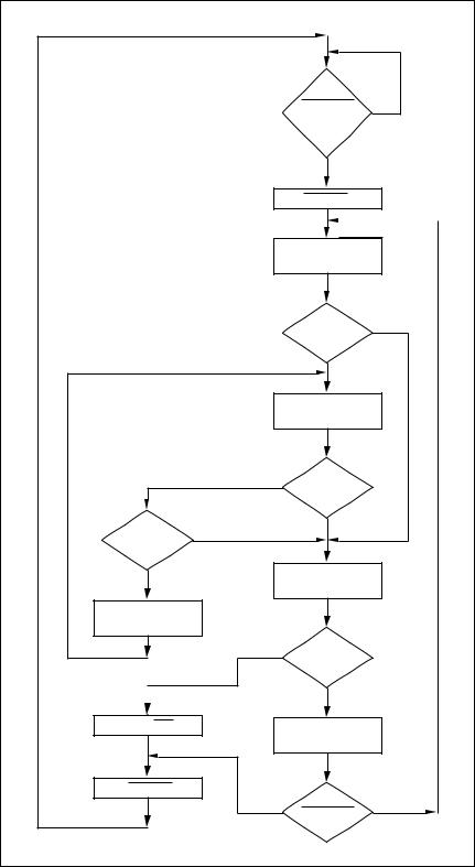
Figure 1 shows the instruction fetch and execute cycle.
|
|
Has |
|
|
|
HALTREQ |
NO |
|
|
gone low to |
|
|
|
high ? |
|
|
|
YES |
|
|
|
Set HALTED high |
|
|
|
Fetch Instruction |
|
|
|
Message |
|
|
|
Command |
YES |
|
|
|
|
|
|
Error ? |
|
|
|
NO |
|
|
|
Execute |
|
|
|
Instruction |
|
|
YES |
Retry |
|
|
Required ? |
|
|
|
|
|
|
Retry |
YES |
NO |
|
|
|
||
Count = 0 ? |
|
|
|
|
|
|
|
NO |
|
Output |
|
|
Report Word |
|
|
|
|
|
|
Decrement |
|
|
|
Retry Count |
|
|
|
|
YES |
INT. |
|
|
Required ? |
|
|
|
|
|
|
|
|
NO |
|
Pulse IRQ |
|
Increment |
|
|
|
Instruction Address |
|
SET HALTED low |
|
|
|
|
YES |
HALTREQ |
NO |
|
|
|
|
|
|
= 0 ? |
|
Figure 1: BC Instruction Fetch and Execute Cycle
8/41
PASSIVE MONITOR
The terminal may be configured into a Passive Monitor (or Bus Monitor) merely by selecting the appropriate Function Code of the Instruction word. By doing this the terminal will not take part in any further Instruction execution but instead will monitor the selected bus for data transmissions.
INTERRUPT / RETRY CAPABILITY
The terminal has certain in-built functions which permit the terminal to retrieve situations which would normally cause a greater degree of subsystem intervention. This is achieved by having an automatic retry facility in-built to the terminal which is selectable from the Instruction word. In this case both the condition and number of attempts for which the terminal must try may be specified. After completion of the required number of attempts, terminal operation may be halted with the possibility of an interrupt generated also.
MA3690/1/3
The interrupt facility provides a means of more direct subsystem interaction in the event of a failure. Similar flags are required to be set in the Instruction word before a selectable interrupt may be generated. This form of interrupt also includes an Interrupt Always flag whose application may be used to determine subsystem/system timing requirements.
It should be noted that an interrupt may also be generated by the error checking procedures of the terminal which verify aspects of the Instruction word and associated Receive/ Transmit command words.
STANDBY BUS CONTROLLER
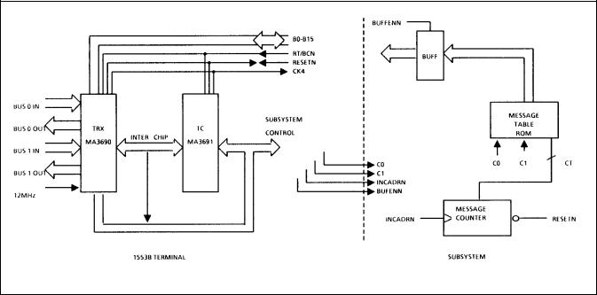
The terminal provides a number of signals to the subsystem for message addressing and execution. Two address lines are provided (CO, Cl) plus a signal to increment an external counter (INCADRN). This, together with the onchip sequencing, error checking, etc., enables a standby bus controller, using a fixed table of messages, to be realised in few devices as shown in Figure 2. It is therefore possible to attain a standby BC on a single 6 x 4 PCB card.
Figure 2: Standby Bus Controller
9/41

MA3690/1/3
FULL BUS CONTROLLER
To make use of the SOS chipset’s capabilities a processorbased system would be more applicable. A block diagram of such a system, using shared store technique is shown in Figure 3. In this, the instruction word store would be alterable by the processor for use in various system conditions, i.e. a basic message table would initialy be set up with the processor monitoring the results of execution from the report word store and / or the interrupt request (IRQN) line. On detection of an erroneous condition, the processor could write a new message table to test the RT in error by, for example, a self test mode command. The inclusion of automatic retry, with a maximum of 3 retries, in the instruction word, removes the requirement from the processor to retry under simple RT faults, e.g., status bit set.
Figure 3: Full Bus Controller
10/41
SUBSYSTEM INTERFACE
The terminal / subsystem interface consists of a 16 bit bidirectional data highway and a number of control lines, many of which are of optional use. The subsystem lines have been arranged such as to allow a simple shared store technique to be readily implemented but sufficient flexibility has been designed to allow optimisation of the interface for a particular subsystem design.
REMOTE TERMINAL MODE
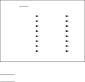
On initialisation, the RT address, address parity and broadcast enables are loaded from the subsystem via the data highway, Figure 4. The subsystem status bits are also loaded in a similar manner when required, Figure 5.
This terminal uses two distinct methods for dealing with non mode data and mode data. In the first, a busy request / acknowledge handshake is used to ensure no data transfer takes place when the subsystem is busy thus ensuring no addressing / data conflict of the main data store. Mode data, however, may be transferred even if the subsystem has declared itself busy. This represents a departure from previous chipset philosophy.
The validation of a data transfer also depends on data type. For non mode data, a data transfer request / acknowledge handshake is used to transfer each data word to or from the subsystem (both RT and BC) with a good block received (GBRN) denoting a correct transfer. For mode data, a mode data transfer (MDTN) is used to signal a mode data word with correct transfer being denoted by mode data received (MDRN). Thus, dependant on application, the l/O signals may be significantly reduced.
An RT subsystem interface signal transfer is shown in Figure 6.
BIT WORD
0
0
TX Timeout Bus 1 TX Timeout Bus 0
Terminal Flag Inhibited 0
Bus 1 Shutdown
Bus 0 Shutdown
Illegal Broadcast
Word Count High
Word Count Low
Illegal Command Illegal T/R Bit Loop Test Failure
SS Handshake Failure TX Timeout Error
15 |
14 |
13 |
12 |
11 |
10 |
9 |
8 |
7 |
6 |
5 |
4 |
3 |
2 |
1 |
0 |
|
|
|
|
|
|
|
|
|
|
|
|
|
|
|
|
MA3690/1/3
The terminal contains a 16 regisiter, called BIT word, which records message errors and terminal status information. The entire BIT word contents are reset by power up initialisation or a legal mode command to reset remote terminal. The conditions for the setting of the BIT, and any additional reset conditions are given for each signal.
The contents of the BIT word register shall not be altered by any of the following legal mode commands. Transmit Status Word (TSW), Transmit Last Command (TLC) and Transmit BIT Word (TBW).
Transmitter Timeout Error
This BIT shall be set to logic one if transmitter timeout occurs while the terminal is tranmitting. In addition, if the terminal is issued with a legal mode command to Initiate Self Test (code 00011) this bit shall be set if the range transmitter timeout mechanism does not operate within the of 660 μs to 800 μs.
Subsystem Handshake Failure
This bit shall be set to logic one if the subsystem does not acknowledge a terminal request to transfer a data word in time for the transfer to take place correctly.
Loop Test Failure
At all times while the terminal is transmitting the relevant receiver circuitry checks for an absence of transmission or any sync, Manchester, parity or contiguity error in the terminals transmission. This bit shall be set to logic one if any of these error conditions are detected.
Illegal T/R Bit
This bit shall be reset to logic zero by the reception of any valid command word with the exception TSW,TLC and TBW.
This bit shall be set to logic one if a valid mode command is received with a transmit/receive (T/R) bit opposite to that specified by MIL-STD-1553B.
Illegal Command
This bit shall be reset to logic zero by the reception of any valid command word with exceptions TSW, TLC and TBW.
This bit shall be set to logic one if any of the following conditions arise:
(a)The ILLEGAL COMMAND line to the subsystem status latch is low at the time when INCMD goes active low.
(b)A valid mode command is received with a reserved mode code and the ALLOW CODE line to the subsystem staus latch is high at the time when INCMD goes low.
(c)An illegal transitter shutdown mode command is received.
11/41
MA3690/1/3
Word Count Low
This bit shall be reset to logic zero by the reception of any valid command word with the exception of TSW, TLC and TBW.
This bit shall be set to logic one if fewer valid data words are received than specified by the preceding command word.
Word Count High
This bit shall be rest to logic zero by the reception of any valid command word with the exception of TSW, TLC and TBW.
This bit shall be set to logic one if the received message is longer than stipulated by the preceeding command word.
Illegal Broadcast
This bit shall be reset to logic zero by the reception of any valid command word with the exception of TSW, TLC and TBW.
This bit shall be set to logic one if a valid command word which by definition requires terminal transmission is received with the broadcast address.
Bus 0 Shutdown
This bit shall be set to logic one if bus 0 is shutdown.
Bus 1 Shutdown
This bit shall be set to logic one if bus 1 is shutdown.
Terminal Flag Inhibited
This bit shall be set to logic one if the internal terminal flag inhibit is set.
Transmitter Timeout on Bus 0
This bit shall be set to logic one if a transmitter timeout has occured on bus 0.
Transmitter Timeout on Bus 1
This bit shall be set to logic one if a transmitter timeout has occured on bus 1.
|
ADEN |
|
|
|
|
|
|
|
||
|
|
|
|
|
|
|
|
|||
|
|
|
|
|
|
|
|
|
|
|
|
RTAD0 |
|
|
|
EN |
|
|
B0 |
||
|
|
|||||||||
|
RTAD1 |
|
|
|
|
|
|
|
B1 |
|
|
|
|
|
|
|
|||||
|
RTAD2 |
|
|
|
|
|
|
|
B2 |
|
|
|
|
|
|
|
|||||
|
RTAD3 |
|
|
BUFFER |
|
B3 |
||||
|
|
|||||||||
|
RTAD4 |
|
|
|
B4 |
|||||
|
|
|
|
|
|
|
|
|||
RTADPAR |
|
|
|
|
|
|
|
B5 |
||
|
|
|
|
|
|
|||||
|
|
|
|
|
|
|
|
|
|
B6 |
BCSTEN0 |
|
|
|
|
|
|
|
|||
|
|
|
|
|
|
|||||
|
|
|
|
|
|
|
|
B7 |
||
BCSTEN1 |
|
|
|
|
|
|||||
|
|
|
|
|
|
|
|
|
||
Note: RTAD0, RTAD1, RTAD2, RTAD3, RTAD4 define the RT address RTADPAR odd parity with the address bits
BCSTEN0 - Broadcast enable for BUS0
BCSTEN1 - Broadcast enable for BUS1
Figure 4: Subsystem RT Address Buffer
12/41

STATENN |
|
|
|
INCMDN |
|
|
|
DBCACC |
G |
OE |
B0 |
|
|
||
SSERR |
|
|
B1 |
SERVREQ |
|
|
B2 |
ILLEGAL COMMANDS |
|
|
B3 |
ALLOW CODE |
|
|
B4 |
RES0 |
|
|
B5 |
RES1 |
|
|
B6 |
RES2 |
|
|
B7 |
|
TRANSPARENT |
|
|
|
|
LATCH |
|
DBACC - Dynamic Bus Acceptance. If low then the Dynamic Acceptance bit of the terminal status word will be set in response to a legal Mode Command for Dynamic Bus Control allocation. After switching to the BC mode of operation the first instruction must be a NOOP.
MA3690/1/3
SSERR - A low will cause the Subsystem flag to be set in the terminal status word.
SERVREQ - A low will set the service request bit of the terminal status word.
ILLEGAL COMMAND - Allows the subsystem to declare any command word illegal. When low the terminal will inhibit data transfers to or from the subsystem, and after message validation will respond with the message error bit set in the terminal status word.
ALLOW CODE - Provides the subsystem with the capability to declare any of the reserved mode codes as being meaningful. If a reserved mode code is received when high the command is treated as illegal and after message validation responds with ME bit set in the terminal status word. If low the most significant bit of the mode code and the T/R bit determine whether any data words are involved and their direction.
RES0, RES1, RES2 - Provides the subsystem the capability of setting any of the currently reserved bits of the terminal status word.
Figure 5: Subsystem Status Latch
Figure 6: Remote Terminal Subsystem Interface Signal Transfer
13/41
 Loading...