


DYNEX MAS28140NC, MAS28140FS, MAS28140FL, MAS28140FE, MAS28140FD Datasheet
...MA28140
Packet Telecommand Decoder
Replaces June 2000 version, DS3839-6.1 |
DS3839-7.0 September 2001 |
The MA28140 Packet Telecommand Decoder (PTD) is a single-chip implementation of the core part of a telecommand decoder, manufactured using CMOS-SOS high performance, radiation hard, 1.5 m technology. The PTD is a full implementation of and fully compliant with the packet telecommand standard ESA PSS-04-107 and the telecommand decoder specification ESA PSS-04-151, these being derived from the corresponding CCSDS standards.
The PTD, which handles 6 NRZ TC input channels, processes the following layers:
Coding Layer
Transfer Layer
Segmentation Layer
Authentication Layer
Command Pulse Distribution
Some of these layers have a telemetry reporting mechanism. The processed TC segment can be transferred to the application either serially or in parallel.
FEATURES
■Single Chip Implementation of all TC Decoder Core Functions
■Built-in Authentication Unit
■Built-in Command Pulse Distribution Unit Core Logic
■Radiation Hard to 1MRads (Si)
■High SEU Immunity, Latch-up Free
■CMOS-SOS Technology
■Conforms to CCSDS Standards
■6 NRZ TC Input Channels
■50Kbps Bit Rate
■Low Power Consumption
■Single 5V Supply
■-55 to +125° C Operation
InterfaceInterfaceInterface |
AuthenticationParallelTelemetry |
1444244431444442444443123 |
|
|
|
FARBUF |
|
CPDUDIV |
123144444244443144424443 |
CPDUBusLocal InterfaceInterfaceMiscellaneous |
|||
|
|
|
|
|
|
CLCWSA |
|
RFAVN |
|
|
|
|
|
|
|
|
|
|
|
|
|
|
|
|
|
||
|
|
|
|
|
|
CLCWCA |
|
VCLSB |
|
|
|
|
|
|
|
|
|
|
|
|
|
|
|
|
|
||
|
|
|
|
|
|
CLCWDA |
|
TMMOD |
|
|
|
|
|
|
|
|
|
|
|
|
|
|
|
|
|
||
|
|
|
|
|
|
CLCWSB |
|
PAR |
|
|
|
|
|
|
|
|
|
|
|
|
|
|
|
|
|
||
|
|
|
|
|
|
CLCWCB |
|
RESETN |
|
|
|
|
|
|
|
|
|
|
|
|
|
|
|
|
|
||
|
|
|
|
|
|
CLCWDB |
|
CLK |
|
|
|
|
|
|
|
|
|
|
|
|
|
|
|
|
|
||
|
|
|
|
|
|
CPDUS |
|
PRIOR |
|
|
|
|
|
|
|
|
|
|
|
|
|
|
|
|
|
||
|
|
|
|
|
|
FAR1S |
|
TEST |
|
|
|
|
|
|
|
|
|
|
|
|
|
|
|
|
|
||
|
|
|
|
|
|
FAR2S |
|
MODE |
|
|
|
|
|
|
|
|
|
|
|
|
|
|
|
|
|
||
|
|
|
|
|
|
AU1S |
|
CONF |
|
|
|
|
|
|
|
|
|
|
|
|
|
|
|
|
|
||
|
|
|
|
|
|
AU2S |
|
SELTC(0-2) |
|
|
|
|
|
|
|
|
|
|
|
|
|
|
|
|
|
||
|
|
|
|
|
|
TMC |
|
DECOD |
|
|
|
|
|
|
|
|
|
|
|
|
|
|
|
|
|
||
|
|
|
|
|
|
TMD |
|
LADR(0-10) |
|
|
|
|
|
|
|
|
|
|
|
|
|
|
|
|
|
||
|
|
|
|
|
|
|
|
|
|
|
|
|
|
|
|
|
|
|
|
|
|
|
|
|
|
|
|
|
|
|
|
|
|
PRDY |
|
LDAT(0-7) |
|
|
|
|
|
|
|
|
|
|
|
|
|
|
|
|
|
||
|
|
|
|
|
|
PBUS(0-15) |
|
RWN |
|
|
|
|
|
|
|
|
|
|
|
|
|
|
|
|
|
||
|
|
|
|
|
|
|
PTD |
BRQN |
|
|
|
|
|
|
|
|
|
|
|
|
|
|
|
|
|
||
|
|
|
|
|
|
AUDIS |
BGRN |
|
|
|
|
|
|
|
|
|
|
|
|
|
|
|
|
|
|||
|
|
|
|
|
|
AUEXT |
|
RAMCSN |
|
|
|
|
|
|
|
|
|
|
|
|
|
|
|
|
|
||
|
|
|
|
|
|
AUST |
|
ROMCSN |
|
|
|
|
|
|
|
|
|
|
|
|
|
|
|
|
|
||
|
|
|
|
|
|
AUBUF |
|
LACCS |
|
|
|
|
|
|
|
|
|
|
|
|
|
|
|
|
|
||
|
|
|
|
|
|
AUEND |
|
LACK |
|
|
|
|
|
|
|
|
|
|
|
|
|
|
|
|
|
||
|
|
|
|
|
|
AUR |
|
|
|
|
|
|
|
|
|
|
|
|
|
|
|
|
|
|
|
|
|
|
|
|
|
|
|
AUTSL |
|
CPDUSTN |
|
|
|
|
|
|
|
|
|
|
|
|
|
|
|
|
|
||
ponder Interface |
Power-Trans |
123123 |
|
|
|
AUSBUF |
|
CPDUEN |
|
|
|
|
MAP Interface |
|
|
|
|
|
|
|
|
||||||
|
|
|
|
|
|
|
|
|
|
||||
|
|
|
GND |
|
MAPADT |
142443 |
|||||||
|
|
|
|
|
|
TCC0-5 |
|
MAPSTN |
|
|
|
|
|
|
|
|
|
|
|
TCS0-5 |
|
MAPCK |
|
|
|
|
|
|
|
|
|
|
|
TCA0-5 |
|
MAPDSR |
|
|
|
|
|
|
|
|
12 |
|
|
|
|
MAPDTR |
|
|
|
|
|
|
|
|
|
|
|
|
|
|
|
|
|
||
|
|
|
|
|
VDD |
|
MAPDATA |
|
|
|
|
|
|
|
|
|
14 |
|
|
|
|
|
|
|
|
||
|
|
|
|
|
|
|
|
|
|
|
|
|
|
|
|
|
|
|
|
|
|
|
|
|
|
|
|
Pin connections
1/72
MA28140
CONTENTS
|
|
|
Page |
Front sheet ............................................................................ |
1 |
||
1. |
Introduction ....................................................................... |
2 |
|
2. |
TC Decoder Subsystem Overview .................................... |
3 |
|
3. |
PTD Architectural Overview .............................................. |
4 |
|
4. |
PTD Functional Description |
|
|
|
4.1 |
Coding Layer ....................................................... |
6 |
|
4.2 |
Transfer Layer ..................................................... |
9 |
|
4.3 |
Authentication Layer .......................................... |
15 |
|
4.4 |
Segmentation Layer ........................................... |
21 |
|
4.5 CPDU ................................................................. |
22 |
|
|
4.6 |
Telemetry Reporting .......................................... |
24 |
5. |
PTD Interfaces |
|
|
|
5.1 |
Physical Channel Interface ................................ |
27 |
|
5.2 |
MAP Interface .................................................... |
27 |
|
5.3 |
Telemetry Interface ............................................ |
30 |
|
5.4 |
Parallel Interface ................................................ |
34 |
|
5.5 |
CPDU Interface .................................................. |
35 |
|
5.6 |
Local Bus Interface ............................................ |
36 |
|
5.7 |
Memories ........................................................... |
36 |
|
5.8 |
External Authentication ...................................... |
41 |
6. |
State After Reset ............................................................. |
42 |
|
7. |
Signal Description ........................................................... |
44 |
|
8. |
Electrical Characteristics and Ratings |
|
|
|
8.1 |
DC Parameters .................................................. |
47 |
|
8.2 |
AC Parameters .................................................. |
48 |
9. |
Package Details |
|
|
|
9.1 |
Dimensions ........................................................ |
65 |
|
9.2 |
Pin Assignment .................................................. |
66 |
10. Radiation Tolerance ...................................................... |
70 |
||
11. Ordering Information ..................................................... |
70 |
||
12. Synonyms ..................................................................... |
71 |
||
REFERENCES
1.“Packet Telecommand Standard” ESA PSS-04-107, Issue 2, April 92.
2.“Telecommand Decoder Specification” ESA PSS-04-151, Issue 1, September 93.
1. INTRODUCTION
This document is the data sheet of the “Packet Telecommand Decoder”, henceforth called the PTD.
The PTD is compatible with the ESA PSS-04-107 standard directly derived from the CCSDS recommendations. This standard is described in references 1 and 2. The data sheet is based on both documents for the description of the protocol. Nevertheless, it was impossible to include the whole reference documents in the data sheet, thus some specific points of the protocol or some descriptions of the recommended hardware implementation have not been included. The reader may find these points in the applicable documents.
CONVENTION
In this document the two conventions described in references 1 and 2 apply:
1. The first bit in the field to be transmitted (i.e. the most left justified bit when drawing a figure) is defined to be Bit 0. When the field is used to express a binary value, the Most Significant Bit (MSB) shall be the first transmitted bit of the field (i.e. Bit 0).
Bit 0 |
Bit N-1 |
N Bit Data Field |
|
|
|
MSB |
LSB |
← First Bit transmitted = MSB |
|
Note: Some of the external interfaces have parallel busses (LADR, LDAT, PBUS, SELTC) which have the opposite bit order specified, i.e. Bit 0 is The Least Significant Bit.
2. An 8-bit word (a byte) is called an OCTET.
2/72
|
|
|
MA28140 |
|
|
Local Bus |
|
|
|
ROM |
|
|
External |
Configuration |
|
|
Authentication |
|
|
|
Unit |
Authentication |
|
|
|
RAM |
|
|
|
|
Back-up |
|
|
|
Power |
TC input |
|
|
Supply |
Transponder |
|
|
|
NRZ or PSK |
|
|
|
I/F |
|
Command |
|
(6 max) |
|
||
|
CPDU |
||
|
PTD |
Pulses |
|
|
I/F |
||
|
|
(256 max) |
|
|
|
|
|
|
|
MAP |
Serial |
|
Clock |
Demultiplexer |
Data link |
|
|
I/F |
(62 max) |
|
Telemetry |
|
|
|
I/F |
|
|
Figure 1: Block Diagram of a TC Decoder Subsystem
2. TC DECODER SUBSYSTEM OVERVIEW
An ESA/CCSDS Telecommand Decoder subsystem including the PTD and fulfilling the receiving-end functions established in the Packet Telecommand Standard (ref 1) is shown in Figure 1.
The PTD requires the following additional hardware to fulfil the requirements of the Telecommand Decoder Specification (ref 2):
•Transponder I/F including demodulators for PSK TC inputs.
•Telemetry I/F. The telemetry reporting signals can be directly connected to a Virtual Channel Multiplexer (ref 3).
•Command Pulse Distribution Unit I/F. This function performs decoding of commands present on the local bus and power amplification. The PTD ASIC associated with the CPDU I/F can manage 256 pulse outputs.
•MAP demultiplexer I/F. This interface is composed of a demultiplexer to provide the TC segment data to various Data Management System interfaces. The demultiplexer is controlled by the MAP data present on the Local Bus.
The PTD ASIC can manage 62 different serial data interfaces (63 if AU is disabled).
•Memories. There are 2 different memories:
-RAM (2Kx8) used to store the received TC data and protocol variables (programme authentication key for instance) and eventually to store the TC segment available for further processing by the Data Management System. If this memory is used to store the recovery LAC counter (Authentication function), it must be a non-volatile memory.
-ROM (1Kx8) divided in two parts:
-Configuration part, used to provide the Mission Specific Data.
-Authentication part, used to provide the fixed Authentication key.
•External Authentication Unit (optional). Although an AU is implemented in the PTD, it is also possible to use an external AU if the mission requires a different authentication algorithm. This external unit accesses the RAM in order to authenticate a TC segment.
3/72

MA28140
3. PTD ARCHITECTURAL OVERVIEW
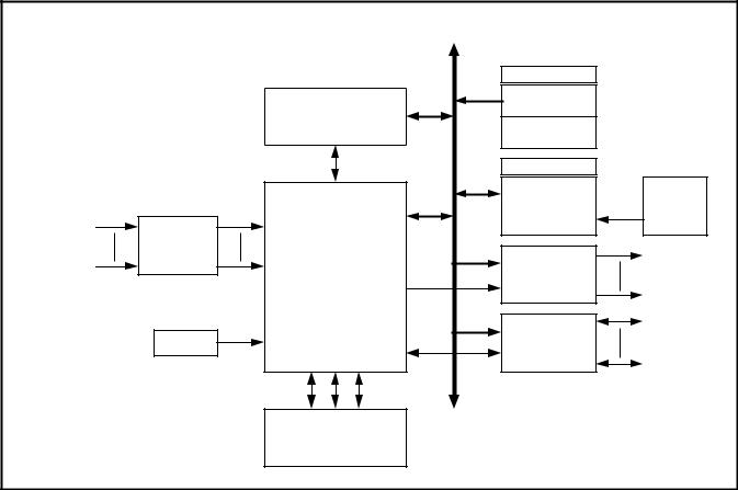
Figure 2 describes the PTD functional architecture which features 7 major blocks described below. Figure 3 shows the CCSDS protocol layer architecture. The PTD deals with the Coding Layer, the Transfer Layer, the Authentication Layer, the Segmentation Layer and a part of the Packetisation Layer of the CCSDS protocol.
CODING LAYER BLOCK
The coding layer block multiplexes the 6 physical TC channel inputs and fulfils the coding layer function described in section 5 of ref.1.
The main tasks performed by the PTD at this level are:
•Start sequence detection and selection of the first active TC input.
•Codeblock error detection and correction.
•Valid codeblock transfer to the above layer.
•Generation of part of the FAR and CLCW status.
TRANSFER LAYER BLOCK
This level is concerned with the processing of the frames received from the coding layer and fulfils the transfer layer function described in section 6 of ref.1.
At this level, the PTD performs the following tasks:
•Clean frame validation.
•Legal frame validation.
•Frame analysis report mechanism.
•Reporting word (16 bit CLCW and part of 32 bit FAR) generation.
AUTHENTICATION UNIT BLOCK
This block (which is optional and can be disabled permanently or during flight) is concerned with the segment data protection, it enables the spacecraft to authenticate the received data. The authentication concept is the “plain text with appended signature” approach, described in Section 8 of ref. 2.
In the PTD architecture this function is implemented on chip. However, a specific interface allows authentication to be performed externally - if another coding algorithm is to be used, the on-chip block can be disabled and an external authentication system can be used.
The block generates a reporting word (Authentication Status = 80 bits) and part of the 32 bit FAR.
SEGMENTATION LAYER BLOCK
This block implements only some of the segmentation layer functions described in section 7 of ref.1. Its purpose is to manage the back-end buffer shared with the FARM-1 block of the transfer layer and to implement the MAP interface in order to demultiplex (with external hardware) the segments dedicated to the different spacecraft applications.
|
EXTERNAL BUS |
|
|
|
|
|
|
|
|
||
|
6447448 |
|
|
|
|
|
|
|
|
||
|
DATA CTL |
AD |
|
|
FAR28...30 |
AUS0...79 |
|
|
|
|
|
|
8 |
11 |
|
|
|
|
CLCW |
|
|
|
|
|
|
|
|
|
|
|
|
|
|
||
|
BUS |
|
|
|
AUTHENTICATION |
CPDUS |
TELEMETRY |
TM interface |
|||
|
|
|
|
|
|||||||
|
|
|
|
FAR |
MODULE |
|
|||||
|
CONTROLLER |
|
|
UNIT |
|
|
|||||
|
|
|
AUS |
|
|
|
|||||
|
|
|
|
|
|
|
|
|
|
||
adr |
|
|
INTERNAL BUS |
|
|
|
|
|
|
||
control |
|
|
|
|
|
|
|
|
|
|
|
data |
|
|
|
|
|
|
|
|
|
|
|
6 |
|
|
|
|
|
|
|
|
|
|
|
CLK |
|
|
CLEAN FRAME |
LEGAL FRAME |
|
|
|
COMMAND PULSE |
|||
6 |
CODING LAYER |
FARM-1 |
SEGMENTATION |
||||||||
VALIDATION |
VALIDATION |
|
DISTRIBUTION |
||||||||
DATA |
BLOCK |
|
BLOCK |
LAYER BLOCK |
|
||||||
6 |
|
BLOCK |
BLOCK |
|
|
UNIT |
|||||
|
|
|
|
|
|
|
|||||
ACTIVE |
|
|
|
|
|
|
|
|
|
|
|
|
|
|
TRANSFER LAYER |
|
|
|
|
|
|
|
|
|
FAR7...12 |
|
|
FAR1...3 |
|
FAR1...3 |
FAR21...26 |
|
|
CPDUS0...15 |
|
|
FAR13...15 |
|
FAR4...6 |
CLCW0...15 |
|
|
|
|
|||
|
FAR18...20 |
|
FAR16,17 |
|
|
MAP interface |
|
|
|||
|
|
|
|
|
|
|
|
|
|||
Figure 2: PTD Internal Architecture
4/72

MA28140
|
|
|
|
|
|
|
|
|
|
|
|
|
|
|
|
EXAMPLE : 256 OCTETS |
|
|
|
|
|
|
|
|
|
|
|
|
|
|
|
|
|
|
|
|
|
|
|
|
|||||||||||||||
|
|
|
|
|
|
|
|
|
|
|
|
|
|
|
|
|
|
|
|
|
|
|
|
|
|
|
|
|
|
|
|
|
|
|
|
|
|
|
|
||||||||||||||||
|
|
|
|
|
|
|
|
|
|
|
|
|
|
|
|
|
|
|
|
|
|
|
|
|
|
|
|
|
|
|
|
|
|
|
|
|
|
|
|
|
|
||||||||||||||
PACKETISATION |
|
|
|
|
|
|
|
|
|
PACKET |
|
|
|
|
|
|
PACKET |
|
|
|
|
PACKET |
|
|
|
|
|
|
|
|
|
|
|
|
|
|
|
|
|||||||||||||||||
LAYER |
|
|
|
|
|
|
|
|
|
HEADER |
|
|
|
|
|
|
|
DATA |
|
|
|
|
ERROR |
|
|
|
|
|
|
|
|
|
|
|
|
|
|
|
|
||||||||||||||||
|
|
|
|
|
|
|
|
|
|
|
|
|
|
|
|
|
|
|
CONTROL |
|
|
|
|
|
|
|
|
|
|
|
|
|
|
|
|||||||||||||||||||||
|
|
|
|
|
|
|
|
|
|
|
|
|
|
|
|
|
|
|
|
|
|
|
|
|
|
|
|
|
|
|
|
|
|
|
|
|
|
|
|
|
|
|
|
|
|
|
|
|
|
||||||
|
|
|
|
1 OCTET |
|
|
|
|
|
|
|
|
|
|
|
|
|
|
|
|
|
|
|
|
|
|
|
|
|
|
|
|
|
|
|
|
|
|
|
|
|
||||||||||||||
|
|
|
|
|
|
|
248 OCTETS |
|
|
|
|
|
|
|
|
|
|
|
|
|
|
|
|
|
|
|
|
|
|
|
|
|
|
|
|
|
|
|
|
|
|
|
|
|
|
|
|
|
|||||||
|
|
|
|
|
|
|
|
|
|
|
1 |
|
|
|
|
|
8 |
|
|
|
|
|
|
|
|
|
|
|
|
|
|
|
|
|
|
|
|||||||||||||||||||
SEGMENTATION |
|
|
|
|
|
|
|
|
|
|
|
|
|
|
|
|
|
|
|
|
|
|
|
|
|
|
|
|
|
|
|
|
|
|
|
|
|
|
|
|
|
|
|
|
|||||||||||
|
|
|
SEGMENT |
|
|
|
FIRST PACKET |
|
|
|
|
|
|
|
|
|
|
SEGMENT |
LAST PACKET |
|
|
|
|
|
|
|
|
|
|
|
|
|
|||||||||||||||||||||||
LAYER |
|
|
|
HEADER |
|
|
|
SEGMENT |
|
|
|
|
|
|
|
|
|
|
HEADER |
|
SEGMENT |
|
|
|
|
|
|
|
|
|
|
|
|
|
|
|
|
||||||||||||||||||
|
|
|
|
|
|
|
|
|
|
|
|
|
|
|
|
|
|
|
|
|
|
|
|
|
|
|
|
|
|
|
|
|
|
|
|
|
|
|
|
|
|
|
|
|
|
|
|
|
|||||||
|
|
|
|
|
|
|
|
|
|
|
|
|
|
|
|
|
|
|
|
|
|
|
|
|
|
|
|
|
|
|
|
|
|
|
|
|
|
|
|
|
|
|
|
|
|
|
|
|
|
|
|
|
|
|
|
|
|
|
|
5 |
|
|
|
|
|
249 (MAX.) |
|
|
|
|
|
2 |
|
|
|
|
|
|
|
5 |
|
|
|
|
9 |
|
|
|
2 |
|
|
|
|
|
|||||||||||||||||
|
|
|
|
|
|
|
|
|
|
|
|
|
|
|
|
|
|
|
|
|
|
|
|
|
|
|
|
|
|
|
|
|
|
|
|
|
|
|
|
|
|
|
|
|
|
||||||||||
TRANSFER |
|
|
|
FRAME |
|
|
|
FRAME DATA |
|
|
|
|
|
|
|
FRAME |
|
|
|
|
|
|
|
FRAME |
|
FRAME DATA |
|
FRAME |
|
|
|
||||||||||||||||||||||||
LAYER |
|
|
|
HEADER |
|
|
|
|
|
FIELD |
|
|
|
|
|
|
|
ERROR |
|
|
|
|
|
|
|
HEADER |
|
|
FIELD |
|
|
|
ERROR |
|
|
||||||||||||||||||||
|
|
|
|
|
|
|
|
|
|
|
|
|
|
|
CONTROL |
|
|
|
|
|
|
|
|
|
|
|
CONTROL |
|
|
||||||||||||||||||||||||||
|
|
|
|
|
|
|
|
|
|
|
|
|
|
|
|
|
|
|
|
|
|
|
|
|
|
|
|
|
|
|
|
|
|
|
|
|
|
|
|
|
|
|
|
|
|
|
|
|
|
|
|||||
|
|
|
|
|
|
|
|
|
|
|
|
|
|
|
|
|
|
|
|
|
|
|
|
|
|
|
|
|
|
|
|
|
|
|
|
|
|
|
|
|
|
|
|
|
|
|
|
|
|
|
|||||
|
|
|
|
|
|
|
|
|
|
|
|
|
|
|
|
|
|
|
|
|
|
|
|
|
|
|
|
|
|
|
|
|
|
|
|
|
|
|
|
|
|
|
|
|
|
|
|
|
|
|
|
|
|
|
|
|
|
|
|
|
|
|
|
|
|
|
|
|
|
|
|
|
|
|
|
|
|
|
|
|
|
|
|
|
|
|
|
|
|
|
|
|
|
|
|
|
|
|
|
|
|
|
|||||||||
CODING |
|
2 |
|
7 |
|
1 |
|
7 |
|
1 |
|
|
|
|
|
|
|
|
|
1 |
|
|
|
7 |
|
|
|
1 |
|
|
4 |
|
3 |
|
|
|
1 |
|
|
8 |
|
||||||||||||||
|
|
|
|
|
|
|
|
|
|
|
|||||||||||||||||||||||||||||||||||||||||||||
|
|
|
|
|
|
|
|
|
|
|
|
|
|
|
|
|
|
|
|
|
|
|
|
|
|
|
|
|
|
|
|
|
|
|
|
|
|
|
|
|
|
|
|
|
|
|
|
|
|
|
|
|
|
||
|
START |
|
INFOR- |
|
ERROR |
|
|
|
|
E.C. |
|
|
|
|
|
|
|
|
|
|
|
E.C. |
|
|
|
|
|
|
E.C. |
|
|
|
FILL |
|
|
E.C. |
|
|
|
TAIL |
|
||||||||||||||
LAYER |
|
SEQUENCE |
|
MATION |
|
CONTROL |
|
|
|
|
|
|
|
|
|
|
|
|
|
|
|
|
|
|
|
|
|
|
|
|
|
|
|
|
SEQUENCE |
|
|||||||||||||||||||
(CODEBLOCK |
|
|
|
|
|
|
|
|
|
|
|
|
|
|
|
|
|
|
|
|
|
|
|
|
|
|
|
|
|
|
|
|
|
|
|
|
|
|
|
|
|
|
|
|
|
|
|
|
|
|
|
|
|
|
|
|
|
|
|
CODEBLOCK |
|
|
CODEBLOCK |
|
|
|
|
|
|
|
|
|
|
|
|
|
|
|
|
CODEBLOCK |
|
CODEBLOCK |
|
|
|
|
|
||||||||||||||||||||||||
LENGTH = 8 |
|
|
|
|
|
|
|
|
|
|
|
|
|
|
|
|
|
|
|
|
|
|
|
|
|
|
|
|
|||||||||||||||||||||||||||
|
|
|
|
|
|
|
|
|
|
|
|
|
|
|
|
|
|
|
|
|
|
|
|
|
|||||||||||||||||||||||||||||||
OCTETS) |
|
|
|
|
No.1 |
|
|
|
No.2 |
|
|
|
|
|
|
|
|
|
|
|
|
|
|
|
|
|
No.36 |
|
|
|
|
No.37 |
|
|
|
|
|
|
|
|
|||||||||||||||
|
|
|
|
|
|
|
|
|
|
|
|
|
|
|
|
|
|
|
|
|
|
|
|
|
|
|
|
|
|
|
|
|
|
|
|
|
|
|
|
|
|
|
|
|
|
|
|
|
|
|
|
|
|
||
PHYSICAL |
|
16 OCTETS |
|
|
|
|
|
|
306 OCTETS |
|
|
|
|
|
|
|
|
|
|
|
|
MIN. 1 OCTET |
|
|
|
|
34 OCTETS |
|
|
|
|
|
|
|
|
|
|
||||||||||||||||||
|
|
|
|
|
|
|
|
|
|
|
|
|
|
|
|
|
|
|
|
||||||||||||||||||||||||||||||||||||
|
|
|
|
|
|
|
|
|
|
|
|
|
|
|
|
|
|
|
|
|
|
|
|
|
|
|
|
|
|
|
|
|
|
|
|
|
|
|
|
|
|
|
|
|
|
|
|
|
|
|
|
|
|
||
|
ACQUISITION |
|
|
|
|
|
|
FIRST CLTU |
|
|
|
|
|
|
|
|
|
|
|
IDLE SEQUENCE |
|
|
|
|
LAST CLTU |
|
|
IDLE SEQUENCE |
|
||||||||||||||||||||||||||
LAYER |
|
SEQUENCE |
|
|
|
|
|
|
|
|
|
|
|
|
|
|
|
|
|
|
|
|
|
|
|
|
|
(OPTIONAL) |
|
||||||||||||||||||||||||||
|
|
|
|
|
|
|
|
|
|
|
|
|
|
|
|
|
|
|
|
|
|
|
|
|
|
|
|
|
|
|
|
|
|
|
|
|
|
|
|
|
|
|
|
|
|
|
|
||||||||
(ESA PLOP-2) |
|
|
|
|
|
|
|
|
|
|
|
|
|
|
|
|
|
|
|
|
|
|
|
|
|
|
|
|
|
|
|
|
|
|
|
|
|
|
|
|
|
|
|
|
|
|
|
|
|
|
|
|
|
|
|
|
|
|
|
|
|
|
|
|
|
|
|
|
|
|
|
|
|
|
|
|
|
|
|
|
|
|
|
|
|
|
|
|
|
|
|
|
|
|
|
|
|
|
|
|
|
|
|
|
|
|
|
|
|
|
|
Figure 3: CCSDS Protocol Layer Architecture
COMMAND PULSE DISTRIBUTION UNIT
The CPDU is integrated into the PTD ensuring higher reliability for this critical function (direct telecommand for spacecraft reconfiguration) than if implemented in an external chip. The critical commands executed by the CPDU are received in specific packets. The CPDU responds to the MAP identifier 0, and to a mission dependent application process identifier (stored in ROM). No segmentation is accepted, the commands must be contained in an unsegmented package. The unit generates a reporting word (CPDU Status = 16 bits).
BUS CONTROLLER
This block is the interface between external memories and on chip modules. Its different functions are:
•address decoding.
•internal and external bus access arbitration.
TELEMETRY MODULE
This block is the interface with the telemetry subsystem. It manages the data report storage using double buffered registers.
5/72
MA28140
4. PTD FUNCTIONAL DESCRIPTION
4.1 CODING LAYER
Overview of the Layer
The coding layer provides the forward error correction capability and synchronisation services used by the Transfer layer. Each Transfer Frame is encoded/embedded in one CLTU (Command Link Transmission Unit), which is the protocol-data unit of the coding layer. At the receiving end of the Coding Layer, a “dirty” symbol stream (plus control information on whether the physical channel is active or inactive) is received from the layer below. Searching for the Start Sequence, the coding layer finds the beginning of a CLTU and decodes the TC Codeblocks. As long as no errors are detected, or errors are detected and corrected, the coding layer passes “clean” octets of data to the Transfer layer. Should any codeblock contain an uncorrectable error, this Codeblock is abandoned and considered as Tail Sequence, no further data is passed to the layer above and the Coding Layer returns to a Start Sequence searching mode until it detects one. The coding layer also generates part of the CLCW and FAR status.
The PTD can handle up to 6 TC input interfaces, the data bit rate on these inputs should not exceed 50 Kbits per second when using the Authentication Unit. If the Authenication unit is not used the symbol rate could exceed 200kBits/sec (not guaranteed).
Standard Data Structures Within the Layer
A CLTU is made up of three distinct protocol data elements:
-one 16-bit Start Sequence,
-one or more TC Codeblocks of a fixed length of 8 octets to encode the protocol data unit from the layer above,
-one Tail Sequence of length equal to that of the TC Codeblock, i.e. 8 octets.
Start |
First |
|
Last |
Tail |
Sequence |
Codeblock |
•••••••••• |
Codeblock |
Sequence |
|
|
|
|
|
16 Bits |
Variable Number of Codeblocks |
8 Octets |
||
|
|
|
|
|
The Start Sequence marks the beginning of the TC Codeblock field within a CLTU. It consists of a 16-bit synchronisation pattern represented in hexadecimal as EB90, where the first transmitted octet is EB.
The TC Codeblock field consists of one or more TC Codeblocks. The codeblock length of received data is fixed and set to 8 octets (information field: 7 octets).
|
P0 (MSB) |
P6 |
|
P7 (LSB) |
|
|
|
|
|
Information Field |
Error Control Field |
|
Filler Bit |
|
|
7 parity bits |
|
|
|
|
|
|
|
|
7 Octets |
|
1 Octet |
|
|
The Tail Sequence marks the end of the TC Codeblock Field within a CLTU. The length of the Tail Sequence is that of a TC Codeblock. Reference 1 specifies that its pattern should
be alternating “zeros” and “ones”, ending with a “one” (55 ....
55 in hexadecimal), but any double error codeblock, or single error codeblock with filler bit equal to 1 will be interpreted as Tail Sequence by the PTD.
Synchronization and TC Input Selection
Synchronization is performed by searching for the Start Sequence simultaneously on all active TC inputs. The Start Sequence detection allows one bit error anywhere in the 16-bit pattern. Furthermore due to NRZ coding ambiguity on the incoming bit stream, it is possible to detect the inverted Start Sequence pattern in order to choose between positive or negative representation for further NRZ data processing. If an inverted Start Sequence is detected, the following bit stream is inverted until the Tail Sequence is encountered.
Two different modes to perform the TC channel selection are supported, selectable with the PRIOR configuration input:
Standard Mode (PRIOR = 0), in which all TC inputs TC0 to TC5 have the same priority, and the search for a Start Sequence is performed on all active TC channels simultaneously.
Priority Mode (PRIOR = 1), in which two inputs are assigned an absolute priority.
Note: This mode is not compliant with Ref. 1, and is intended for applications with specific requirements on unconditional access to the TC decoder. If this mode is used, a thorough analysis of potential failure modes and the built-in timeout mechanisms is recommended.
Standard Mode
The TC input selection locks the selection multiplexer on the first TC channel where the Start Sequence is found. The selection mechanism is restarted once a Tail Sequence or a codeblock rejection has been detected. Furthermore, as a protection mechanism in case of RF receiver breakdown, a timeout mechanism is provided; if the TC channel clock is not detected during a certain time, the TC selection mechanism is reactivated in order not to remain lacked on a Channel without a clock signal.
The timeout value between two successive edges of the TC channel clock is: 3932160
tCK < TC clock timeout < 4587520 tCK, with tCK being the system clock period. With a
system clock frequency fCK of 4MHz this equals 0.98s <TC clock timeout < 1.15s.
6/72

Priority Mode
In this mode two inputs have priority, according to the following rule: TC0 > TC1 > TC2 = TC3 = TC4 = TC5. When neither the TC0 input nor the TC1 input is active, the selection between the inputs TC2 to TC5 is performed as in the Standard Mode.
As soon as the TC active signal of TC0 is asserted, this TC input is selected, and the 5 other channels are inhibited. In case another input was already selected and receiving data, it is abandoned. The TC0 input remains selected until one of the following events:
a1: its TC active signal becomes inactive, or
b1: its bit clock has not been received for a period equal to the TC clock timeout, or
c1: no Start Sequence has been detected for a period equal to the TC active timeout, or
d1: a Tail Sequence or a codeblock rejection has occurred.
Upon events (a1) and (d1), the selection logic returns to the search state. Upon events (b1) and (c1), the TC0 input is ignored (i.e. considered inactive) until the event (a1) occurs.
When the TC0 input is inactive (including the case of a timeout as described above), as soon as the TC active signal of TC1 is asserted, this TC input is selected, and the lower priority inputs TC2 to TC5 are inhibited. In case any of these inputs was already selected and receiving data, it is abandoned. The TCl input remains selected until one of the following events.
a2: its TC active signal, becomes inactive, or
b2: its bit clock has not been received for a period equal to the TC clack timeout, or
c2: no Start Sequence has been detected for a period equal to the TC active timeout, or
d2: a Tail Sequence or a codeblock rejection has occurred, or
e2: the TCO active signal is asserted.
Upon events (a2) and (d2), the selection logic returns to the search state. Upon events (b2) and (c2), the selection logic ignores the TC1 input until event (a2) occurs. Upon event (e2) the TCl input is inhibited and the TC0 input is selected as previously described.
The TC clock timeout value between two successive edges of the TC channel clock is: 3932160 tCK < TC clock timeout < 4587520 tCK. With a system clock frequency fCK of 4 MHz this equals 0.98s <TC clock timeout < 1.15s.
The TC active timeout value between two successive Start Sequence patterns being detected is 334233600 tCK < TC active timeout < 335399960 tCK. With a system clock frequency fCK of 4MHz this equals 83.5s < TC active timeout < 83.9s.
MA28140
Codeblock Decoding
Codeblock decoding is performed for each received codeblock. At the sending end, a systematic block coding procedure processing 56 bits per Codeblock and generating 7 parity check bits per Codeblock is used. The parity check bits are then complemented and placed into the codeblocks: P0 (MSB) through P6 are located in the first seven bits (MSBs) of the last octet of the codeblock. The last bit of the last octet, P7 (LSB), is a filler bit appended to complete the 8-bit Error Control Field. This Filler Bit should normally be a zero, except for the Tail Sequence. The code is a (63,56) modified Bose-Chaudhuri- Hocquenghem (BCH), based on the following polynomial generator: g(x)=x7+x6+x2+1. A single error correction & double error detection mode is provided by using this code.
The following table describes the Decoding Strategy of the codeblocks:
ERRORS DETECTED |
FILLER BIT |
DECISION |
|
VALUE |
|
no errors |
ignored |
codeblock |
|
|
accepted |
even number of errors |
ignored |
codeblock |
|
|
rejected |
odd number of errors |
ignored |
codeblock |
with a binary syndrome |
|
rejected |
value equal to all zeros |
|
|
odd number of errors |
0 |
codeblock |
with a binary syndrome |
|
accepted |
value different from all |
|
correction of |
zeros |
|
a single error |
odd number of errors |
1 |
codeblock |
with a binary syndrome |
|
rejected |
value different from all |
|
|
zeros |
|
|
CLTU Management
CLTU decoding consists of the states and events summarized in the following table and state diagram:
|
|
E4 |
|
|
E1 |
|
|
S1 |
S2 |
E3 |
S3 |
|
|||
INACTIVE |
SEARCH |
E2(b) |
DECODE |
|
|
|
E2(c)
E2(a)
Figure 4: CLTU Decoder State Diagram
7/72
MA28140
State Number |
State Name |
State Definition |
S1 |
INACTIVE |
All telecommand channels are inactive (no bit lock is achieved) |
|
|
or no bit modulation is detected. |
S2 |
SEARCH |
Incoming bit stream is searched, bit by bit, for the Start |
|
|
Sequence pattern. |
S3 |
DECODE |
Codeblocks, which are either free of error or which can be |
|
|
corrected, are received and decoded, and their information |
|
|
octets are transferred to the layer above |
|
|
|
Event Number |
Event Name |
Event Definition |
E1 |
CHANNEL ACTIVATION |
Bit modulation is detected and bit lock is achieved: |
|
|
telecommand bit stream is present |
E2 (a) (c) |
CHANNEL |
Deactivation of the TC Active Signal |
|
DEACTIVATION |
|
(b) |
CLTU ERROR |
More than 37 codeblocks accepted in the CLTU |
|
|
or Timeout on the TC Clock signal |
|
|
or Activity on a channel having higher priority in priority mode |
E3 |
START SEQUENCE |
The Start Sequence pattern has been detected, signalling the |
|
FOUND |
beginning of the first codeblock of the CLTU |
E4 |
CODEBLOCK |
A codeblock is found uncorrectable (erroneous codeblock or |
|
REJECTION |
tail sequence). No information octet from this codeblock is |
|
|
transferred to the layer above |
Codeblock transfer is performed in a serial way to the above layer (Transfer layer). Two indication signals are provided to the above layer - one indicating the whole frame duration, the other asserted each time a 7 octets block is being transferred.
The following rules apply to the data transfer between the Coding Layer and the Transfer Layer:
•When the first Candidate Codeblock is affected by an event E4 or by an event E2, the CLTU is abandoned. No Candidate Frame is transferred to the Transfer Layer.
•When the first Candidate Codeblock is found to be error free, or if it contained one error which has been corrected, its information octets (i.e. 7 octets) are transferred to the Transfer Layer. The decoding of the CLTU continues until one of the following events occurs:
1- when an event E4 (codeblock rejection) occurs for any of the 37 possible Candidate Codeblocks the decoder returns to the search state S2 with the following actions:
-The codeblock is abandoned
-No information from that codeblock is transferred to the layer above
-The Coding Layer indicates to the Transfer Layer the end of transfer of the Candidate Frame.
2- when an event E2 (channel deactivation) occurs the decoder returns to the inactive state (for the channel) with the following actions:
-The CLTU is aborted,
-The CLTU is reported as abandoned,
-A signal is sent to the Transfer Layer to indicate that the entire block of octets making up the Candidate Frame must be erased.
3- When an event E2(b) (CLTU error) occurs, the decoder returns to the search state with the following actions:
-The CLTU is aborted,
-The CLTU is reported as abandoned,
-A signal is sent to the Transfer Layer to indicate that the entire block of octets making up the Candidate Frame must be erased.
A CLTU error occurs in the following cases:
-More than 37 codeblocks have been accepted in the CLTU,
-A timeout on the TC clock signal occurs,
-Activity on a channel having higher priority is detected in priority mode.
The DECOD output is activated when the CLTU decoder state is S3.
8/72
MA28140
4.2 TRANSFER LAYER
Overview of the Layer
The Transfer Layer implements the following sublayers:
-The Frame Error Control Sublayer which ensures that only “clean” frames are transferred to the sublayer above by using a CRC error syndrome verification.
-The Frame Header Sublayer verifies the conformity of the relevant frame header fields by using the Legal Frame Validation process before passing the frame to the FARM1.
-The “Frame Acceptance and Reporting Mechanism One” or FARM1 ensures that frames are processed in the correct sequence.
There are three types of TC transfer frames:
-two types for the Sequence-Controlled Service: AD and BC frames
-one type for the Expedited Service: BD frames
The Sequence-Controlled Service is used for normal spacecraft communications. It concerns essentially TC Transfer Frames carrying TC segments: the AD frames. To configure the AD machine, special control frames are used called BC frames.
The Expedited Service is used for recovery in the absence of the telemetry downlink or during unexpected situations. It is only concerned with TC transfer frames carrying TC segments: the BD frames.
Standard Data Structures Within the Layer
The major fields of the TC Transfer Frame are shown below:
5 octets |
1 to 249 octets |
2 octets |
Frame Header |
Frame Data Field |
Frame Error |
|
|
Control Field |
Frame Header
The structure of the frame header is given below:
•Virtual channel identifier. It is used as a spacecraft subidentifier. It can provide an identification of the spacecraft telecommand chain selected for operating the spacecraft.
•Frame length. This field specifies the number of octets contained within the entire TC transfer frame:
Field Value = (Total number of octets) - 1
•Frame sequence number. This number is denoted as N(S). It is set to different values:
-for AD frames it should be set to the Transmitter Frame Sequence Number and it is compared to the Receiver Frame Sequence Number V(R) stored in the PTD, to control the transfer of a sequence of frames (see the FARM-1 process)
-for BC and BD frames it should be set to all zeros.
Except for the bypass and control command flags, the values of the first three header octets are programmed in the external ROM.
In the abbreviations AD, BD and BC, A stands for Acceptance check of N(S), B stands for Bypass of A, C stands for Control and D stands for Data. AC is an illegal combination because Control Commands cannot reliably use a transfer service which they are meant to modify.
Frame Data Field
The frame data field is of variable length from a minimum of 1 octet to a maximum of 249 octets. When the frame is a data frame (type AD or BD), it contains a TC segment. When the frame is a BC frame, this field can contain 2 control commands to configure the FARM-1 process:
• the UNLOCK command. The FARM-1 has a built in mechanism which will go into a Lockout state whenever it receives a type-AD frame containing a frame sequence number N(S) outside the limits of the FARM-1 Sliding Window. The UNLOCK command provides a mechanism to reset the Lockout condition. The UNLOCK command is encoded as a single octet with the value: 00000000.
|
|
2 octets |
|
|
1 |
octet |
1 octet |
1 octet |
version |
bypass |
control |
reserved |
spacecraft |
virtual |
reserved |
frame |
frame |
number |
flag |
command |
field A |
ID |
channel |
field B |
length |
sequence |
|
|
flag |
|
|
ID |
|
|
number |
2 |
1 |
1 |
2 |
10 |
6 |
2 |
8 |
8 |
A description of the fields of the frame header is given below:
•Version number, Reserved field A and Reserved field B should always be 00 (ref 1).
•Bypass flag and control command flags. Their values are given in the next table:
Bypass Flag |
Control Command Flag |
Interpretation |
0 |
0 |
AD frames |
0 |
1 |
ILLEGAL |
1 |
0 |
BD frames |
1 |
1 |
BC frames |
|
|
|
• Spacecraft identifier. This field provides the identification of the spacecraft being commanded.
• The SET V(R) command. The SET V(R) command allows V(R) to be preset to any desired value. The SET V(R) command is encoded as three octets with the values:
10000010 00000000 XXXXXXXX
The value to be set into V(R) is stored in the third octet.
Frame Error Field
The frame error field is a mandatory 16-bit field which occupies the two trailing octets of the TC Transfer Frame. It is a cyclic redundant code (CRC) generated with the polynom X16+X12+ X5+1 with the shift register being initialised to all ones before processing each frame (refer to ref 2 for a complete description of this field). The CRC is only used for error detection by the frame and not for error correction.
9/72
MA28140
Standard Procedures Within the Layer
The Clean Frame Validation Process
On receiving a new frame, the Clean Frame Validation process performs the following tasks:
-the number of octets in the frame is checked to be greater than 7 octets,
-the transfer frame is assumed to be a version 1 frame,
-the frame length field is checked to be compliant with the real number of octets of the frame,
-the number of fill octets is verified to be minimum zero and maximum six,
-the fill octets are removed,
-the CRC error syndrome verification is carried out.
All candidate frames passing all the preceding validation checks are declared clean and transferred immediately to the Legal Frame Validation process. Frames failing any of the preceding tests are declared dirty and are erased.
The Legal Frame Validation Process
On receiving a clean frame, the Legal Frame Validation process performs the following validation checks:
-the version number is checked to be as defined in the ROM,
-the reserved fields A and B are checked to be as defined in the ROM,
-the value of the spacecraft ID is checked to be as defined in the ROM,
-the value of the Virtual Channel ID is checked to be as defined in the ROM and by the VCLSB input,
-the Bypass and Control Command flags must combine legally,
-the BC frames must contain a valid control command (either UNLOCK or SET V(R)),
-for a BC or BD frame the Frame Sequence Number field must be set to all zeros.
The LSB of the VC ID is indirectly defined from a dedicated pin VCLSB; it allows easy configuring of a pair of redundant TC decoders.
-VCLSB = 1: The VC ID LSB read from the ROM is inverted.
-VCLSB = 0: The VC ID LSB read from the ROM is not inverted.
All candidate frames passing all the preceding validation checks are declared legal and transferred immediately to the FARM-1 process. Frames failing any of the preceding tests are declared illegal and erased.
The FARM-1 Process
THE FARM-1 VARIABLES
The Frame Acceptance and Reporting mechanism (FARM-1) is described by a finite state machine represented by the FARM-1 state table. The FARM-1 maintains a set of variables which are described below:
•The State. This may be one of the following:
-Open (S1)
-Wait (S2)
-Lockout (S3)
This variable represents the state of the FARM-1 automaton. In Open State, the FARM-1 accepts frames and passes them to the above layer. In Wait State, there is no buffer space available in which to place any further received data of type AD. The protocols leaves the Wait State upon receipt of a buffer release signal from the Higher Layer. Lockout is entered if the protocol machine detects an error. It is a safe state in that no user data (AD frames) will be accepted or transferred to the Higher Layer. The only accepted data frames are the BD frames, but even in this case the protocol machine remains in lockout state. The protocol machine leaves the Lockout State upon receipt of an UNLOCK control command.
•The Lockout Flag. This is set to 1 whenever the protocol is in the Lockout State.
•The Wait Flag. This is set to 1 whenever the protocol is in Wait State.
•The Retransmit Flag. This is set to 1 whenever the protocol machine knows that an AD
frame has been lost in transmission or has been discarded because there was no buffer space available. This flag is reset to 0 upon the successful receipt of a frame with N(S)=V(R), the receipt of a SET V(R) control command (unless in Lockout State) or receipt of an UNLOCK control command.
•FARM B counter. This is incremented whenever
a valid BD or BC frame arrives. This counter is a 2 bit wraparound counter.
•Receiver Frame Sequence Number V(R). This records the value of N(S) expected to be
seen in the next AD frame.
•The buffer management variable. The PTD maintains a flag indicating the number of the back end buffer. The AUBUF output pin provides the value of this flag (the back end and front end buffers are represented in Figure 6). The number of the TC channel on which the data stored in the back-end buffer has been received is provided on the output pins (SELTC2-0).
•FARM Sliding window variables. The purpose of these are to protect FARM-1 against the unauthorised transfer of a sequence of frames such that the Frame Sequence Number N(S) of one or more of these frames will exceed the current value of the V(R) counter. The FARM Sliding Window concept applies only to AD frames.
The FARM Sliding Window is defined in terms of two variables:
-the width of the positive part referred to as PW
-the width of the negative part referred to as NW
The FARM Positive window area starts with V(R) and extends PW frames in the positive direction. The FARM Negative window starts at V(R) - 1 and extends NW frames in the negative direction.
10/72
MA28140
POSITIVE WINDOW AREA = PW
N(S)=V(R)+PW- 1
DISCARD FRAME & SET RETRANSMIT FLAG
LOCKOUT AREA = 256-W
|
|
N(S)=V(R)+1 |
|
|
ACCEPT |
DISCARD |
|
FRAME & |
|
SET V(R)=V(R)+1 N(S)=V(R) |
|
FRAME & GO TO |
|
|
|
N(S)=V(R)-1 |
|
LOCKOUT |
|
|
|
|
|
STATE |
|
|
|
DISCARD FRAME |
|
-NW N(S)=V(R)
NEGATIVE WINDOW AREA = NW
Figure 5: The FARM Sliding Window Concept
A Frame Sequence Number N(S) falls outside the FARM Sliding Window i.e. in the Lockout Area when:
N(S)>V(R)+PW-1
N(S)<V(R)-NW
In this case, the Lockout flag is set.
When N(S) falls inside the FARM Sliding Window, one of the following three cases can occur:
• First case
N(S)=V(R)
The frame is accepted
• Second Case
N(S)>V(R) and
N(S)£V(R)+PW-1
The frame is in the positive window and does not contain the expected Frame Sequence Number. The Frame is discarded and the retransmit Flag is set.
• Third Case
N(S)<V(R) and
N(S)³V(R)-NW
The frame is in the negative window and is discarded without any other action being taken.
11/72
MA28140
THE FARM-1 PROCESS DESCRIPTION
At the user end of the FARM-1 process the TC segments are delivered as a buffer of accepted data. No distinction is made between a TC segment delivered by means of an AD frame and one delivered by a BD frame. However, the management of the common FARM-1 back end buffer is affected as follows:
• BD Frames:
When a frame of this type is accepted by the FARM-1, the TC segment it contains shall be placed in the back end buffer of the FARM-1 even if this buffer still contains data (partially read or not ) in which case this data will be erased, an abort signal sent to the Segment Layer to signal the erasure and the new data signalled as arrived. This implies an Event E10.
• AD frames:
When a frame of this type is accepted by the FARM-1, the TC segment it contains is placed in the back end buffer of the FARM- 1 only when the buffer is available (empty). If the buffer still contains data, the newly arrived frame is discarded (erased) as shown by the FARM-1 state table (Event E2 in table 1).
The definitions used in the FARM-1 State Table are listed below:
•“Valid frame arrives” means that the Legal Frame Validation Sublayer has placed a legal frame in the front-end buffer. If the frame is a data frame (AD or BD) and if the FARM-
1accepts it, the back end buffer is allocated for the data.
•“Accept” for an AD frame is subject to a buffer available signal. When no back end buffer is available (Event E2) the frame is discarded. The data is then made available for the Authentication Layer, or the Segmentation Layer if Authentication is disabled.
•“Accept” for a BD frame means that the TC segment is placed in the back end buffer even when this buffer still contains data, in which case this previous data is erased (event E10). The Wait concept does not apply to BD frames. The data is available for the Authentication Layer, or the Segmentation Layer if Authentication is disabled.
S t a t e Na me |
O P E N |
WAI T |
LO CKO UT |
|
|
Normal state to |
Wait Flag is on |
Lockout Flag is |
|
Main Feature of State |
accept frames |
|
on |
|
State Number |
(S1) |
S(2) |
S(3) |
|
|
|
|
E v e nt |
|
|
|
E v e nt Condit ions |
|
Numbe r |
O P E N |
WAI T |
LO CKO UT |
|
|
N(S)=V(R) |
A buffer is |
E1 |
Accept frame, |
Not applicable |
Discard |
|
|
available for this |
|
V(R):=V(R)+1R |
|
|
|
|
frame |
|
etransmit |
|
|
|
|
|
|
Flag:=0 |
|
|
|
|
|
|
(S1) |
|
(S3) |
Valid AD frame |
N(S)=V(R) |
No buffer is |
E2 |
Discard, |
Discard |
Discard |
arrives |
|
available for this |
|
Retransmit |
|
|
|
|
frame |
|
Flag:=1, |
|
|
|
|
|
|
Wait Flag:=1 |
|
|
|
|
|
|
(S2) |
(S2) |
(S3) |
|
N(S)>V(R) |
and |
E3 |
Discard, |
Discard |
Discard |
|
N(S)<V(R) +PW-1 |
|
Retransmit |
|
|
|
|
i.e. inside |
positive |
|
Flag:=1 |
|
|
|
part of sliding |
window and >V(R) |
|
(S1) |
(S2) |
(S3) |
|
N(S)< |
|
|
|||
Table 1: The FARM-1 State Table
12/72
|
|
|
|
|
MA28140 |
|
|
|
|
|
|
|
|
E v e nt |
|
|
|
E v e nt |
Condit ions |
Numbe r |
O P E N |
WAI T |
LO CKO UT |
|
N(S)<V(R) and N(S)> |
E4 |
Discard |
Discard |
Discard |
(Cont') Valid |
V(R)-NW i.e. inside |
|
|
|
|
|
negative part of sliding |
|
(S1) |
(S2) |
(S3) |
|
window |
|
|||
AD frame |
N(S)>V(R)+PW-1 and |
E5 |
Discard |
Discard |
Discard |
arrives |
N(S)<V(R)-NW i.e.outside |
|
|
|
|
|
sliding window |
|
Lockout |
Lockout |
|
|
|
|
Flag:=1 |
Flag:=1 |
|
|
|
|
(S3) |
(S3) |
(S3) |
|
|
E6 |
Accept, Increment |
Accept, Increment |
Accept, Increment |
|
|
|
FARM-B Counter |
FARM-B Counter |
FARM-B Counter |
Valid |
BD frame arrives* |
|
|
|
|
|
|
|
(S1) |
(S2) |
(S3) |
|
|
E7 |
Increment FARM-B |
Increment FARM-B |
Increment FARM-B |
|
|
|
Counter, |
Counter, |
Counter, |
|
|
|
Retransmit Flag:=0 |
Retransmit Flag:=0, |
Retransmit Flag:=0, |
|
|
|
|
Wait Flag:=0 |
Wait Flag:=0, Lockout |
Valid |
Unlock BC frame arrives |
|
|
|
Flag:=0 |
|
|
|
(S1) |
(S1) |
(S1) |
|
|
E8 |
Increment FARM-B |
Increment FARM-B |
Increment FARM-B |
|
|
|
Counter, |
Counter, |
Counter, |
|
|
|
Retransmit Flag:=0 |
Retransmit Flag:=0 |
|
|
|
|
V(R):=V*(R) |
Wait Flag:=0 |
|
Valid Set V(R) to V*(R) BC frame arrives |
|
|
V(R):=V*(R) |
|
|
|
|
|
(S1) |
(S1) |
(S3) |
|
|
E9 |
Discard |
Discard |
Discard |
Invalid frame arrives |
|
|
|
|
|
|
|
|
(S1) |
(S1) |
(S3) |
|
|
E10 |
Ignore |
Wait Flag:=0 |
Wait Flag:=0 |
Buffer release signal |
|
|
|
|
|
|
|
|
(S1) |
(S1) |
(S3) |
|
|
E11 |
Report value of: |
Report value of: |
Report value of: V(R), |
|
|
|
V(R), |
V(R), |
Lockout Flag, |
|
|
|
Lockout Flag, |
Lockout Flag, |
Wait Flag, |
|
|
|
Wait Flag, |
Wait Flag, |
Retransmit Flag, |
CLCW report time |
|
Retransmit Flag, |
Retransmit Flag, |
FARM-B Counter |
|
|
|
|
FARM-B Counter |
FARM-B Counter |
|
|
|
|
(S1) |
(S2) |
(S3) |
* Note: Event E6 implies that Event E10 also occurs. When in state S2, an event E6 will lead to state S1. Table 1: The FARM-1 State Table (continued)
13/72

MA28140
Buffer Management
Once the data is validated (Clean, Legal and Frame Validation processes passed), it is transferred from the frontend buffer to the back-end buffer for use by the segmentation layer. Only one back-end buffer is managed by the PTD. This mechanism is depicted in figure 6 below:
|
N Segment Reception |
|
FRONT END BUFFER |
|
|
Segment n |
|
|
Coding and |
|
|
Transfer |
Segmentation Layer |
Applications |
Layers |
|
|
Segment n-1 |
CPDU |
CPDU I/F |
BACK END BUFFER |
|
|
|
|
Segment n-1 |
|
|
CPDU BUFFER |
|
N+1 Segment Reception |
|
BACK END BUFFER |
|
|
Segment n |
|
|
Coding and |
|
|
Transfer |
Segmentation Layer |
Applications |
Layers |
|
|
Segment n+1 |
CPDU |
CPDU I/F |
FRONT END BUFFER |
|
|
|
|
Segment n |
|
|
CPDU BUFFER |
Figure 6: Buffer Management
14/72
4.3 AUTHENTICATION LAYER
Structure of the Authenticated Segments
The TC segment is the protocol data unit of the Segmentation Layer. The general format of an authenticated TC Segment is specified in Section 10 of ref.1. The particular format of an authenticated TC segment for the PTD is the following:
(a)The length of the signature field of the Authentication Tail is 5 octets.
(b)The length of the Authentication Tail is 9 octets (5 octets for the signature + 4 octets for the LAC); the maximum length of the TC Segment is 249 octets (Segment Header (1 octet) + Segment Data Field (239 octets) + Authentication Tail (9 octets)), and its minimum length 10 octets (Segment Header (1 octet) + Authentication Tail (9 octets)).
|
|
|
|
|
SEGMENT |
SEGMENT |
|
|
|
SEGMENT |
HEADER |
|
DATA FIELD |
TRAILER |
|
|
|
Sequence |
MAP |
|
|
(optional) |
|
|
|
Flags |
Identifier |
|
|
|
|
|
|
2 bits |
6 bits |
|
variable |
9 octets |
|
<---------------- |
1 octet ------------ |
>< from 9 to 248 octets----- ------ |
> |
||||
The segment trailer is optional and has a fixed length of 9 octets. The following table summarizes the management of the Segment Trailer.
Ty pe of |
Ty pe of Fra me |
S e gme nt Tra ile r |
Aut he nt ic a t ion |
|
|
Internal AU |
Authenticated frame |
segment trailer (9 octets length) |
|
Not authenticated frame |
no segment trailer |
External AU |
Authenticated frame |
segment trailer (9 octets length) |
|
|
if AuTsl=0, |
|
|
no segment trailer if AuTsl=1 |
|
Not authenticated frame |
no segment trailer |
AU disable |
All |
no segment trailer |
The selection of MAPs that are deemed to carry authenticated TC segments takes into account the possibility to associate MAP IDs in pairs when packet re-assembly is required. Therefore, authenticated MAPs are selected by pairs, using the 5 LSBs of the MAP identifier field of the Segment Header. The selection mechanism is such that it will point at the last pair of MAP identifiers (counting upwards from MAP 0) that carries authenticated segments. The value identifying this particular pair of identifiers is called the Authenticated MAP ID Pointer and is stored in ROM.
For example, selecting MAP 4 (i.e. Authenticated MAP ID Pointer = 4) means that the first 5 pairs of MAPs (i.e. MAP 0 and 32, MAP 1 and 33, MAP 2 and 34, MAP 3 and 35, MAP 4 and 36) are expected to carry authenticated TC segments.
MA28140
Overview of the Layer
This optional layer is implemented on-chip but a connection to an external Authentication Unit is also implemented in case another implementation is desired. The choice of the AU is done by means of a dedicated configuration input AUEXT:
•AUEXT = 1: the internal AU is disabled and the external AU is used,
•AUEXT = 0: the internal AU is used and the external AU is disabled.
MAP 63 is reserved for AU configuration commands when authentication is disabled. It is possible to bypass this layer (when no authentication is required) by means of a dedicated configuration input AUDIS. In this case, segments are passed directly to the segmentation layer .The values of the AUDIS pin are:
•AUDIS = 1: the internal or external AU is disabled,
•AUDIS = 0: the internal or external AU is enabled.
When the AU is disabled, the TC segment does not have an AU tail (the last nine octets are not deleted), the Authenticated MAP ID Pointer has no meaning and MAP 63 is considered as a standard MAP (the data is output on MAP number 63 without removing the AU tail).
An 80 bit length status, AUS, is generated by this block and fetched by the telemetry system in order to send it back to the ground segment.
The Authentication Processor
The authentication method specified in references 1 and 2 consists of generating a 40-bit digital signature using a transformation under a secret key applied to the TC Segment. This authentication signature is appended to the TC segment and guarantees to the recipient that the TC Segment is authentic with respect to its sender and its contents.
An incoming TC Segment is authenticated by performing the same transformation made by the transmitting end, and by comparing the received signature with the onboard-generated one. A functional diagram of the Authentication Processor is shown below. There are four main parts:
-the Hashing Function;
-the Hard Knapsack;
-the Deletion Box;
-the Signature Comparator.
They are described in the next four subsections. Not apparent on the functional diagram of Figure 7 is the organisation of the secret Authentication Keys stored in the Authentication Processor. This is described in the section on AU Control Commands on page 18.
15/72
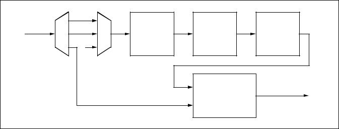
MA28140
THE HASHING FUNCTION
One purpose of the Hashing Function is to compress the variable amount of data bits constituted by the extended message x into a pre-signature P of fixed length (60 bits). The device realising the Hashing Function is a 60-bit linear feedback shift register (LFSR), as shown in Figure 8. The 60 feedback coefficients C0, C1,......,C59 are part of the Authentication Key.
The LFSR is initialised to the 60-bit value P’ = 1000....000 (where Bit P0 = 1) before the process of each authenticated TC Segment begins. P will be the value in the LFSR after the last bit of the variable-length extended message x has been shifted in. The extended message x (x = [m,l,z]) consists of the following data elements, placed one after the other in that order:
-the received message m, i.e., the TC Segment (variable from 1 to 240 octets) without the Authentication Tail;
-the received LAC value l, i.e., 4 octets (2 bits of LAC ID, plus 30 bits of LAC Count);
-three octets of virtual fill z, consisting of 24 zeros.
The purpose of the 24 bits of virtual fill is to ensure that the Hashing Function is provided with a minimum of data bits. The 24 bits of virtual fill z are generated by the PTD. Note that since m (the TC Segment) cannot be equal to zero, the total length of an authenticated TC Segment (i.e., [m,l,s]) cannot be smaller than 10 octets (Segment Header (1 octet) + Authentication tail (9 octets)). Anything smaller than 10 octets is rejected as being too short.
THE HARD KNAPSACK
The purpose of the Hard Knapsack is to ensure that it is not possible to deduce the presignature P from the signature S. The Hard Knapsack is based on the concept of the modular knapsack. It consists of 60 weights (numbered from W0 to W59, each weight being 48 bits long) and is defined by the following transformation:
j=59
S' = (åPjWj) mod 248
j=0
where the bits Pj of the presignature P select the corresponding weights Wj of the knapsack.
The result is the 48-bit knapsack sum S’. The most significant bit of the sum is called S’0.
THE DELETION BOX
The Deletion Box deletes the 8 least significant bits of the 48-bit knapsack sum S’, i.e., bits S’40 through S’47. The result is the 40-bit authentication signature S (numbered from Bit 0 to Bit 39, as for signature s).
THE SIGNATURE COMPARATOR
The Signature Comparator compares the received 40-bit signature s with the onboard generated 40-bit signature S.
TC |
m |
|
|
|
|
|
|
|
Segment |
|
x |
|
P |
|
S' |
|
S |
(m, l, s) |
l |
Hashing |
Hard |
Deletion |
||||
|
z |
|
Function |
|
Knapsack |
|
Box |
|
|
|
|
|
|
|
|
|
|
|
|
|
|
S |
|
|
|
|
|
|
|
|
|
Signature |
|
Signature Valid |
|
|
|
|
|
s |
Comparator |
|
|
|
Figure 7: Functional Diagram of the Authentication Processor
16/72

MA28140
x (i) |
|
P1 (i) |
P2 (i) |
P3 (i) |
P59(i) |
P0 |
(i) |
||||
|
C0 |
C1 |
C2 |
C3 |
C59 |
|
Figure 8: Realisation of the Hashing Function |
|
|||
THE AUTHENTICATION KEY
The Authentication Key consists of: |
|
|
60 x 48-bit Hard Knapsack Weights = |
2880 bits = |
360 octets |
60 x 1-bit Hashing Function coefficients = |
60 bits = |
8 octets |
|
|
|
Full Authentication Key = |
2940 bits = |
368 octets |
The system includes two such 2940-bit keys:
-a fixed, mission-unique Authentication Key, called the Fixed Key;
-an in-flight programmable Authentication Key, called the Programmable Key.
(a) Fixed Key
The Fixed Key is required for start-up and emergency (recovery) operations. The Fixed Key is stored in the external ROM as part of the Mission-Specific Data.
(b) Programmable Key
The Programmable Key is required for all normal operations. The contents of the Programmable Key reside in the RAM where it can be modified by means of Authentication Control Commands specifically defined for that purpose. The format of these Change Programmable Key Block Control Commands, which are specified in the section on AU Control Commands (page 18), allows any 5-octet block to be modified starting at any of the 368 octet boundaries.
The Supervisor
The Supervisor consists of four main parts:
-the Logical Authentication Channel (LAC) Registers;
-the Final Authorisation Function;
-the Control Command Processor;
-the Deletion Function.
They are briefly described in the next four subsections.
THE LAC COUNTERS
A LAC Counter is basically a 30-bit counter which is used to associate every TC segment with an authentication sequence number. The purpose of this number is to protect the system against attacks by ensuring that identical TC segments will not have the same signature except at very large intervals of time. The LAC counter is incremented by one every time a TC segment is successfully authenticated (and only then). The LAC counter value used for authenticating each TC segment is uplinked with each signature.
Three LAC Registers are provided:
-one Principal LAC register (LAC ID = 00);
-one Auxiliary LAC register (LAC ID = 01);
-one Recovery LAC register (LAC ID = 10).
Bits 0 and 1 of the LAC are fixed in order to select the LAC Register to be used for the final authorisation of a TC Segment. For what concerns the 30 bits of LAC Count (Bits 2 through 31, where the LSB is Bit 31), they are implemented as follows:
-The Principal and Auxiliary LAC counters have 30 bits.
-The Recovery LAC counter has 8 bits (the LSBs 24-31) whereas the remaining 22 bits (2-23) are permanently set to 1.
THE FINAL AUTHORISATION FUNCTION
When the received signature s of a TC Segment compares with the onboard-generated signature S, the contents of the received LAC Count field is compared with the contents of the indicated LAC Register. If both contents are found equal, there are two cases:
- The TC Segment was transferred on a MAP to be authenticated with a MAP ID lower or equal to the MAP ID pointer. In this case, the TC Segment is authorised for transfer to the Segmentation Layer.
17/72
MA28140
- The TC Segment was transferred on MAP 63 (i.e., MAP 111111), which is dedicated to the transfer of Authentication Control Commands. In this case, the Control Command Processor is authorised to further process the TC Segment, which will never be transferred to the Segmentation Layer.
In both cases, the contents of the indicated LAC Register is incremented by one.
THE CONTROL COMMAND PROCESSOR
The function of the Control Command Processor is to execute the special TC Segments called Authentication Control Commands after being authorised by the Final Authorisation Function. The formats of the various Authentication Control Commands are specified in the section on AU Control Commands next. Any TC Segment not conforming to the specified formats (i.e., both in length and in contents) are rejected and reported as not executable.
THE DELETION FUNCTION
The Deletion Function deletes the Authentication Tail of all TC Segments authorised by the Final Authorisation Function. The complete authentication process is meant to be transparent to an observer placed at the receiving end of the Segmentation Layer.
AU Control Commands
It is necessary to differentiate TC Segments containing the Authentication Control Commands required to reconfigure the AU. This is done by allocating the TC Segment Header contents “all ones” to these particular segments, i.e.:
-Sequence Flags set to 11 (Unsegmented)
-MAP ID set to 111111 (MAP63)
TC Segments containing the Authentication Control Commands shall always be authenticated. The formats of the Authentication Control Commands are organised in three groups as follows:
-One octet of TC Segment Header for all three groups.
-One octet following the Segment Header to specify the Control Command Identifier
-Zero, four or eight octets of Control Command Data Field, depending on the group.
Table 2 gives the complete list of Authentication Control Commands, with Group numbers, Control Command IDs and Command Names. Table 3 shows the format of the TC Segment for each Group, complete with Authentication Tail. Each Control Command is specified in the next subsections.
DUMMY CONTROL COMMAND
The purpose of this command is to serve as NOP (No Operation) for testing purposes. After being authenticated, this Control Command will have no effect. However, since the AU has authenticated the Dummy Segment, the contents of the LAC Register used during the authorisation process have been incremented and a telemetry report prepared accordingly.
SELECT KEY CONTROL COMMANDS
(a) Select Fixed Key
The AU selects the Fixed Key prior to authenticating the TC Segment:
-If authentication is successful, the Fixed Key remains selected.
-If authentication is unsuccessful, the key previously in use remains selected.
(b) Select Programmable Key
The AU selects the Programmable Key for authentication of the TC Segment:
-If authentication is successful, the Programmable Key remains selected.
-If authentication is unsuccessful, the key previously in use remains selected.
LOAD FIXED KEY IN PROGRAMMABLE KEY MEMORY CONTROL COMMAND
This command reloads the Fixed Key set in the Programmable Key memory with a single command instruction. The key used for authenticating the TC Segment containing the Control Command will be whatever key was selected in the AU at the time the command was transmitted.
SET NEW LAC COUNT VALUE CONTROL COMMAND
The purpose of this Control Command is to set the value of one of the three programmable LAC Counters: Principal, Auxiliary or Recovery with LAC Identifiers 00, 01 and 10 respectively. If the LAC Identifier is set to 11, the command is not executed and reported as not executable. As soon as the TC Segment is authorised by the authentication process, the specified LAC Count value is forced into the selected LAC Register. Note that the 22 MSBs of the 30-bit Recovery LAC Register are permanently set to all ones, therefore those same bits in a Set New Recovery LAC Count Value Control Command are ignored by the AU. The key used for authenticating the TC Segment containing the Control Command will be whatever key was selected in the AU at the time the command was transmitted.
18/72

MA28140
|
|
GRO UP |
|
CO NTRO L CO MMAND |
|
|
CO MMAND NAME |
|
|
|
|
||||||||||||
|
|
|
|
IDENTIFIER (8 BITS) |
|
|
|
|
|
|
|
|
|
|
|
|
|
|
|
|
|||
|
|
|
|
|
|
0000 0000 |
|
|
|
|
|
|
|
DUMMY |
|
|
|
|
|||||
|
|
GRO UP 1 |
|
|
|
0000 0101 |
|
|
|
|
|
|
|
SELECT FIXED KEY |
|
||||||||
|
|
|
|
|
0000 0110 |
|
|
|
SELECT PRO GRAMMABLE KEY |
|
|||||||||||||
|
|
|
|
|
|
|
|
|
|
||||||||||||||
|
|
|
|
|
|
0000 0111 |
|
|
|
LO AD FIXED KEY IN PRO GRAMMABLE KEY MEMO RY |
|
||||||||||||
|
|
GRO UP 2 |
|
|
|
0000 1001 |
|
|
|
SET NEW LAC CO UNT VALUE |
|
||||||||||||
|
|
GRO UP 3 |
|
|
|
0000 1010 |
|
|
|
CHANGE PRO GRAMMABLE KEY BLO CK A |
|
||||||||||||
|
|
|
|
|
0000 1011 |
|
|
|
CHANGE PRO GRAMMABLE KEY BLO CK B |
|
|||||||||||||
|
|
|
|
|
|
|
|
|
|
||||||||||||||
|
|
|
|
|
|
|
Table 2: List of Authentication Control Commands |
|
|
|
|
||||||||||||
|
|
1 octet |
|
|
|
1 octet |
|
|
|
9 octets |
|
|
|
|
|||||||||
|
|
|
|
|
|
|
|
|
|||||||||||||||
|
|
Segment Header |
|
Control Command Identifier |
|
|
|
Authentication Tail |
|
|
|
|
|||||||||||
|
11111111 |
|
|
00000*** |
|
|
|
LAC+Signature |
|
|
|
|
|||||||||||
Group 1 Control Command, 11 Octets |
|
|
|
|
|
|
|
|
|
|
|
|
|
|
|
|
|||||||
|
|
1 octet |
|
|
1 octet |
|
|
4 |
|
octets |
|
|
|
|
9 octets |
|
|
||||||
|
|
|
|
|
|
|
|
|
|||||||||||||||
|
|
Segment Header |
Control Command |
|
|
|
LAC value |
|
to be set |
|
|
|
Authentication Tail |
|
|
||||||||
|
|
|
|
|
|
Identifier |
|
|
|
|
|
|
|
|
|
|
|
|
|
|
|
|
|
11111111 |
|
00001001 |
|
|
|
LAC ID 2 bits |
|
LAC Count 30 bits |
|
|
|
LAC + Signature |
|
|
|||||||||
Group 2 Control Command, 15 Octets |
|
|
|
|
|
|
|
|
|
|
|
|
|
|
|
|
|||||||
|
|
1 octet |
|
|
1 octet |
|
|
|
1 octet |
|
7 octets |
|
|
|
9 octets |
|
|||||||
|
|
|
|
|
|
|
|
|
|
||||||||||||||
|
|
Segment Header |
Control Command |
|
|
|
Start Address of |
|
Key specific pattern |
|
|
|
|
Authentication Tail |
|
||||||||
|
|
|
|
|
|
Identifier |
|
|
new 40 bit Keyblock |
|
to be encoded |
|
|
|
|
|
|
||||||
|
|
11111111 |
|
0000101* |
|
|
|
|
|
|
|
|
|
|
|
|
LAC+Signature |
|
|||||
Group 3 Control Command, 19 Octets
Table 3: Formats of Authentication Control Commands (Full TC Segment)
19/72

MA28140
CHANGE PROGRAMMABLE KEY BLOCK CONTROL COMMANDS A AND B
Two such Control Commands are provided to cover the full size of the Programmable Key:
-Command A concerns the first 256 octet boundaries.
-Command B concerns the last 112 octet boundaries.
It is possible to load a 5-octet (40 bits) block starting from any of the 368 octet boundaries. Any transmission using the unused boundaries of Command B (from 113 to 255) is ignored and reported as non-executable. The key used for authenticating the TC Segment containing one of these Control Commands will be whatever key was selected in the AU at the time each Control Command was received. Once the TC Segment has been authorized by the authentication process, the TC Segment, minus the 40-bit signature s (i.e. [m,l]) is complemented and passed once more through the
signature-building process, i.e. through the Authentication Processor. The 24 bits of virtual fill z are inserted as before, i.e., they are not complemented, but remain all zeros. The result of the process is a 40-bit pseudo-signature which, instead of being sent to the Signature Comparator, is loaded in the Programmable Key memory, starting at the octet location indicated by the start address field, as follows:
-Bits 32 through 39 of pseudo-signature at the indicated octet location;
-Bits 24 through 31 of pseudo-signature at the next location (start address + 1);
-And so on, until Bits 0 through 7 are loaded at location start address + 4.
Any arbitary procedure can be used for changing the key, starting from any of the 368 octet boundaries.
RAM
Mapping
200
201
202
203
204
205
206
207
2FF
300
367
368
369
36A
36B
36C
36D
36E
36F
Address provided in the
Control command (decimal)
|
000 |
40 |
W0 (40 to 47) |
47 |
|
|
||
|
001 |
32 |
W0 (32 to 39) |
39 |
|
|
||
|
|
|
|
|
|
|
|
|
|
002 |
24 |
W0 (24 to 31) |
31 |
|
|
||
|
|
|
|
|
|
|
|
|
|
003 |
16 |
W0 (16 to 23) |
23 |
|
|
||
|
004 |
8 |
W0 (8 to 15) |
15 |
|
|
||
|
|
|
|
|
|
|
|
|
|
005 |
0 |
W0 (0 to 7) |
7 |
|
|
||
|
|
|
|
|
|
|
|
|
|
006 |
40 |
W1 (40 to 47) |
47 |
|
|
||
Bank A |
007 |
32 |
W1 (32 to 39) |
39 |
|
|
||
|
|
|
|
|
|
|
|
|
|
|
|
|
|
|
|
|
|
|
|
|
|
|
|
|
|
|
|
|
|
|
|
|
|
|
|
255 |
16 |
W42 (16 to 23) |
23 |
|
|
|||
|
|
|
||||||
B |
000 |
8 |
W42 (8 to 15) |
15 |
|
|
||
Bank |
|
|
|
|
|
|
|
|
|
|
|
|
|
|
|
|
|
|
|
|
|
|
|
|
|
|
|
|
|
|
|
|
|
|
|
103 |
0 |
W59 (0 to 7) |
7 |
|
|
|||
|
|
|
||||||
|
104 |
|
|
59 C (59 to 56) |
56 |
|
|
|
|
105 |
55 |
C (55 to 48) |
48 |
|
|
||
|
106 |
47 |
C (47 to 40) |
40 |
|
|
||
|
107 |
39 |
C (39 to 32) |
32 |
|
|
||
|
|
|
|
|
|
|
|
|
|
108 |
31 |
C (31 to 24) |
24 |
|
|
||
|
109 |
23 |
C (23 to 16) |
16 |
|
|
||
|
110 |
15 |
C (15 to 8) |
8 |
|
|
||
|
|
|
|
|
|
|
|
|
|
111 |
7 |
C (7 to 0) |
0 |
Note: Bit 0 is the MSB |
|||
|
|
|
|
|
|
|
|
|
Figure 9: Organisation of the Programmable Key Memory
20/72
4.4 SEGMENTATION LAYER
Overview of the Layer
The segmentation layer provides the means to distribute several distinct streams of variable-length data units (e.g. the TC packets) to different applications by providing a number of service access points called the Multiple Access Points (MAPs). The data flow on each stream can be controlled by the receiving application using handshake control.
A TC segment consists of three distinct protocol data elements:
-an 8-bit segment header, the purpose of which is to identify the MAP connection and flag the sequential position of the segment relative to the complete TC Packet,
-a segment data field, of maximum length 248 octets, which contains all or a portion of a TC Packet,
-the 9-octet Segment Trailer specific to authenticated segments is removed by the authentication layer.
Standard Data Structures Within the Layer
The structure of the TC segment is given below:
|
|
|
|
|
SEGMENT DATA |
|
|
SEGMENT |
HEADER |
|
FIELD |
|
|
Sequence |
MAP |
|
|
|
|
Flags |
Identifier |
|
|
|
|
2 bits |
6 bits |
|
variable |
<--------------- |
1 octet ------------ |
><- from 0 to 248 octets -> |
|||
Segment Header
The Segment Header is the first octet (octet 0) of the TC segment structure. The Segment Header is divided into two major fields as follows:
- Sequence Flags (bits 0 & 1): this field is used by the segmentation protocol to indicate the sequential position of the segment relative to the complete data unit (e.g. the TC Packet). The flags are interpreted as follows:
Bit 0 (MSB) |
Bit 1 |
Interpretation |
0 |
1 |
First segment |
0 |
0 |
Continuation segment |
1 |
0 |
Last segment |
1 |
1 |
Unsegmented |
When the flags are set to 11 this means that the TC Segment Data Field contains an entire TC Packet. Except for the CPDU described in section 4.5, these flags are ignored by the PTD.
- Multiplexed Access Point (MAP) Identifier: this 6-bit field enables up to 64 MAP connection addresses to be associated with a single Virtual Channel. The PTD supports MAP 1 to 63 as externally available MAPs. MAP 0 is dedicated to the CPDU. MAP 63, when AU is enabled, is reserved for AU commands; when the AU is disabled, MAP 63 is processed by the segment layer like a standard MAP (see section 4.3).
MA28140
Segment Data Field
The segment data field may vary from 0 to 248 octets maximum. When the optional Segment Trailer is used, the maximum length of the segment data field will be reduced by 9 octets.
Standard Procedures Within the Layer
The following segmentation layer functions are implemented in the PTD:
-the back-end buffer for the accepted TC segment. The back-end buffer is shared between the Transfer Layer and the Segmentation Layer.
-the MAP interface.
Upon reception of a new segment the Segment Layer performs the following operations:
-Checks whether the segment is authenticated or not.
-Starts the AU process if the segment is authenticated and if the AU is not disabled. The Segment Layer waits for the completion of the AU process (internal or external). A security mechanism is implemented, in case of AU locking mechanism the user can stop the AU process by activating the AU disable signal. In this case, the segment layer stops waiting for the AU completion process and the content of the back end buffer is lost.
-Checks if the frame is a CPDU command (MAP 0). In this case, the CPDU layer is activated and no data is output on the MAP interface.
-Checks if the frame is an AU command (MAP 63) and the AU is not disabled. In this case no data is output on the MAP interface.
-For a MAP 1 to 62 and for MAP 63 if the AU is disabled, the data is provided in serial or in parallel via the MAP interface. The MAP output frequency for serial MAP is selectable by reading a value associated with each MAP in the external ROM (see section 5.2).
21/72

MA28140
4.5 COMMAND PULSE DISTRIBUTION UNIT
General Requirements
The CPDU is a simple unit that is solely accessible from ground. The aim of this unit is to generate pulses to drive certain actuators (e.g. relays). The CPDU is identified by the Application Process Identifier placed in the TC Packet Header. The Application Identifier of the CPDU is programmable in ROM at addresses 006 and 007.
Functional Description
The CPDU receives TC segments, each segment containing a complete TC Packet. TC segments having a MAP equal to zero are carrying CPDU commands. It must be noted that if the internal AU is enabled, MAP0 segments are always authenticated. When a new segment carrying CPDU commands has arrived, two cases are possible:
-the CPDU is still executing previous CPDU commands. In this case, the incoming TC segment is ignored, whether it was transferred in an AD or BD transfer frame.
-the CPDU is idle. The incoming TC segment is copied from the back end buffer to the CPDU buffer for checking and execution by the CPDU.
An important point must be noted: there is no packetisation layer abort command associated with the CPDU. Once it has accepted a TC Packet, the CPDU cannot release it until all command instructions specified in that packet have been executed.
The CPDU performs first the clean validation process which verifies the complete packet (CRC, packet length, segmentation flags). If the clean validation process is successful, the CPDU performs the legal validation process, which checks the content of the Packet Headers. The result of the two previous verifications is reported in the 16 bits CPDU status. For a dirty or illegal CPDU Packet, the CPDU buffer is erased. The execution of the CPDU commands is possible only if all the verifications succeed.
A short description of the fields of the CPDU Packet is given below:
-version number: 3-bit field occupying the 3 MSBs of the packet header. To be compliant with ref.1, these 3 bits should be 000.
-type bit: this bit identifies if the Packet is telemetry type (type bit = 0) or telecommand type (type bit = 1). To be compliant with ref 1, this bit should be set to 1.
-data field header flag: this indicates the presence (data field header flag = 1) or absence (data field header flag = 0) of a data field header within the packet data field. To be compliant with ref 1, this bit should be set to 0.
-application process identifier: this field identifies the particular process to which the CPDU Packet is sent.
-sequence flags: this two-bit field indicates if the packet is a first, last or intermediate component of a higher layer data structure. For CPDU Packets, these two bits shall be equal to 11.
-packet sequence count: this 14-bit field allows a particular TC Packet to be identified with respect to others occurring within a telecommand session. This field is reported in the CPDU status for clean and legal CPDU packets.
-packet length: this field specifies the number of octets contained within the packet data field, by indicating the number of octets in data field minus 1.
-packet data field: this field contains the CPDU commands and the CRC for packet error control.
Checking the CPDU-Specific TC Packet
The CPDU Packet format is shown below:
|
|
|
PACKET HEADER (48 bits) |
|
|
|
PACKET DATA FIELD |
|||||
|
|
|
|
|
|
|
|
|
|
|
(variable) |
|
PACKET |
IDENTIFICATION |
|
PACKET |
PACKET |
DATA |
APPLIC- |
PACKET |
|||||
|
|
|
|
|
|
SEQUENCE |
LENGTH |
FIELD |
ATION |
ERROR |
||
|
|
|
|
|
|
CONTROL |
|
HEADER |
DATA |
CON- |
||
|
|
|
|
|
|
|
|
|
|
|
|
TROL |
version |
type |
|
data field |
|
applicat- |
Sequence |
|
Packet |
|
|
|
|
number |
|
|
header |
|
ion |
Flags |
|
Name or |
|
|
|
|
|
|
|
flag |
|
process |
|
|
Sequence |
|
|
|
|
|
|
|
|
|
ID |
|
|
Count |
|
|
|
|
3 |
1 |
|
1 |
|
11 |
2 |
|
14 |
|
|
|
|
|
|
16 |
|
|
|
16 |
16 |
variable |
variable |
16 |
||
22/72
 Loading...