


R630
Table of contents
 Loading...
Dell PowerEdge R630
Owner's Manual
Regulatory Model: E26S Series
Regulatory Type: E26S001

Notes, cautions, and warnings
NOTE: A NOTE indicates important information that helps you make better use of your computer.
CAUTION: A CAUTION indicates either potential damage to hardware or loss of data and tells you
how to avoid the problem.
WARNING: A WARNING indicates a potential for property damage, personal injury, or death.
© 2016 Dell Inc. All rights reserved. This product is protected by U.S. and international copyright and intellectual
property laws. Dell and the Dell logo are trademarks of Dell Inc. in the United States and/or other jurisdictions. All other
marks and names mentioned herein may be trademarks of their respective companies.
2016 - 03
Rev. A03

Contents
1 Dell PowerEdge R630 system overview........................................................... 9
Supported configurations for the PowerEdge R630 system...............................................................9
Front panel...........................................................................................................................................10
10 x 2.5-inch hard drive chassis.................................................................................................... 11
Eight x 2.5-inch hard drive chassis................................................................................................13
24 x 1.8-inch hard drive chassis....................................................................................................15
LCD panel.......................................................................................................................................17
Back panel............................................................................................................................................19
Two-riser chassis...........................................................................................................................19
Three-riser chassis.........................................................................................................................21
Diagnostic indicators.......................................................................................................................... 23
Hard drive indicator codes............................................................................................................25
uSATA SSD indicator codes.......................................................................................................... 26
NIC indicator codes.......................................................................................................................27
Power supply unit indicator codes............................................................................................... 27
iDRAC Direct LED indicator codes............................................................................................... 30
Quick Sync indicator codes.......................................................................................................... 32
Locating Service Tag of your system................................................................................................. 33
2 Documentation resources................................................................................ 34
3 Technical specifications.................................................................................... 37
Chassis dimensions............................................................................................................................. 37
Chassis weight.....................................................................................................................................38
Processor specifications..................................................................................................................... 38
PSU specifications...............................................................................................................................38
System battery specifications............................................................................................................. 39
Expansion bus specifications..............................................................................................................39
Memory specifications........................................................................................................................39
Drive specifications.............................................................................................................................40
Hard drives.................................................................................................................................... 40
Optical drive.................................................................................................................................. 40
Ports and connectors specifications..................................................................................................40
USB ports.......................................................................................................................................40
NIC ports........................................................................................................................................41
Serial connector.............................................................................................................................41
VGA ports.......................................................................................................................................41
Internal Dual SD Module............................................................................................................... 41
3

Video specifications.............................................................................................................................41
Environmental specifications..............................................................................................................41
Particulate and gaseous contamination specifications............................................................... 43
Standard operating temperature..................................................................................................44
Expanded operating temperature................................................................................................ 44
Expanded operating temperature restrictions............................................................................. 45
4 Initial system setup and configuration...........................................................46
Setting up your system....................................................................................................................... 46
iDRAC configuration...........................................................................................................................46
Options to set up iDRAC IP address.............................................................................................46
Options to install the operating system............................................................................................. 47
Methods to download firmware and drivers................................................................................47
5 Pre-operating system management applications........................................49
Options to manage the pre-operating system applications.............................................................49
System Setup.......................................................................................................................................49
Viewing System Setup...................................................................................................................50
System Setup details..................................................................................................................... 50
System BIOS.................................................................................................................................. 50
iDRAC Settings utility.....................................................................................................................74
Device Settings.............................................................................................................................. 74
Dell Lifecycle Controller..................................................................................................................... 75
Embedded system management..................................................................................................75
Boot Manager...................................................................................................................................... 75
Viewing Boot Manager.................................................................................................................. 75
Boot Manager main menu............................................................................................................ 76
PXE boot.............................................................................................................................................. 76
6 Installing and removing system components............................................... 77
Safety instructions............................................................................................................................... 77
Before working inside your system.....................................................................................................77
After working inside your system....................................................................................................... 78
Recommended tools.......................................................................................................................... 78
Front bezel (optional)..........................................................................................................................78
Removing the optional front bezel...............................................................................................78
Installing the optional front bezel................................................................................................ 80
System cover....................................................................................................................................... 81
Removing the system cover..........................................................................................................81
Installing the system cover........................................................................................................... 82
Inside the system................................................................................................................................ 83
Cooling shroud................................................................................................................................... 86
4

Removing the cooling shroud......................................................................................................86
Installing the cooling shroud........................................................................................................ 87
System memory.................................................................................................................................. 87
General memory module installation guidelines.........................................................................89
Mode-specific guidelines............................................................................................................. 90
Sample memory configurations....................................................................................................91
Removing memory modules........................................................................................................94
Installing memory modules.......................................................................................................... 95
Hard drives...........................................................................................................................................97
Removing a 2.5-inch hard drive blank..........................................................................................97
Installing a 2.5-inch hard drive blank........................................................................................... 98
Removing a 1.8-inch hard drive blank......................................................................................... 99
Installing a 1.8-inch hard drive blank........................................................................................... 99
Removing a hot swappable hard drive or SSD...........................................................................100
Installing a hot swappable hard drive.........................................................................................102
Removing a hard drive from a hard drive carrier....................................................................... 103
Installing a hot swappable hard drive into a hot swappable hard drive carrier........................104
Removing a 1.8-inch hard drive from a hard drive carrier........................................................ 105
Installing a 1.8-inch hard drive into a hard drive carrier............................................................106
Optical drive (optional)..................................................................................................................... 106
Removing the optional optical drive.......................................................................................... 106
Installing the optional optical drive............................................................................................ 107
Removing the slim optical drive blank....................................................................................... 108
Installing the slim optical drive blank......................................................................................... 109
Cooling fans.......................................................................................................................................110
Removing a cooling fan.............................................................................................................. 110
Installing a cooling fan.................................................................................................................111
Internal USB memory key (optional).................................................................................................112
Replacing the optional internal USB memory key......................................................................112
Expansion cards and expansion card riser....................................................................................... 114
Expansion card installation guidelines........................................................................................114
Removing expansion card risers................................................................................................. 115
Removing an expansion card...................................................................................................... 117
Installing an expansion card........................................................................................................118
Installing expansion card risers................................................................................................... 119
SD vFlash media card (optional)........................................................................................................121
Replacing an SD vFlash card........................................................................................................121
Internal dual SD module (optional)...................................................................................................122
Removing an internal SD Card....................................................................................................122
Installing an internal SD card...................................................................................................... 123
Removing the optional internal dual SD module.......................................................................123
Installing the optional internal dual SD module ........................................................................125
5

Integrated storage controller card....................................................................................................127
Removing the integrated storage controller card......................................................................127
Installing the integrated storage controller card....................................................................... 129
Network daughter card..................................................................................................................... 131
Removing the network daughter card........................................................................................131
Installing the network daughter card..........................................................................................132
Processors and heat sinks.................................................................................................................134
Removing a heat sink.................................................................................................................. 134
Removing a processor.................................................................................................................135
Installing a processor.................................................................................................................. 139
Installing a heat sink....................................................................................................................140
Power supply units............................................................................................................................142
Hot spare feature.........................................................................................................................143
Removing the power supply unit blank......................................................................................143
Installing the power supply unit blank........................................................................................144
Removing an AC power supply unit........................................................................................... 145
Installing an AC power supply unit.............................................................................................146
Wiring instructions for a DC power supply unit......................................................................... 147
Removing a DC power supply unit.............................................................................................150
Installing a DC power supply unit............................................................................................... 151
System battery...................................................................................................................................152
Replacing the system battery......................................................................................................152
Hard drive backplane........................................................................................................................ 154
Removing the hard drive backplane...........................................................................................154
Installing the hard drive backplane............................................................................................. 161
Control panel assembly.................................................................................................................... 163
Removing the control panel board–eight hard drive system................................................... 163
Installing the control panel board–eight hard drive system..................................................... 164
Removing the control panel–eight hard drive system.............................................................. 165
Installing the control panel–eight hard drive system................................................................ 167
Removing the control panel–10 hard drive and 24 hard drive system.................................... 168
Installing the control panel–10 hard drive system and 24 hard drive system..........................169
VGA module.......................................................................................................................................171
Removing the VGA module.........................................................................................................171
Installing the VGA module...........................................................................................................172
System board.....................................................................................................................................174
Removing the system board....................................................................................................... 174
Installing the system board..........................................................................................................177
Trusted Platform Module..................................................................................................................180
Installing the Trusted Platform Module......................................................................................180
Initializing the TPM for BitLocker users...................................................................................... 181
Initializing the TPM for TXT users............................................................................................... 182
6

7 Using system diagnostics................................................................................183
Dell Embedded System Diagnostics.................................................................................................183
Running the Embedded System Diagnostics from Boot Manager............................................183
Running the Embedded System Diagnostics from the Dell Lifecycle Controller.....................183
System diagnostics controls.......................................................................................................184
8 Jumpers and connectors ............................................................................... 185
System board jumper settings.......................................................................................................... 185
System board jumpers and connectors...........................................................................................186
Disabling a forgotten password........................................................................................................188
9 Troubleshooting your system........................................................................189
Safety first — for you and your system.............................................................................................189
Troubleshooting system startup failure........................................................................................... 189
Troubleshooting external connections............................................................................................189
Troubleshooting the video subsystem.............................................................................................189
Troubleshooting a USB device......................................................................................................... 190
Troubleshooting iDRAC Direct (USB XML configuration)................................................................191
Troubleshooting iDRAC Direct (Laptop connection).......................................................................191
Troubleshooting a serial I/O device................................................................................................. 192
Troubleshooting a NIC......................................................................................................................192
Troubleshooting a wet system......................................................................................................... 193
Troubleshooting a damaged system................................................................................................194
Troubleshooting the system battery................................................................................................ 195
Troubleshooting power supply units................................................................................................195
Troubleshooting power source problems................................................................................. 196
Power supply unit problems.......................................................................................................196
Troubleshooting cooling problems................................................................................................. 196
Troubleshooting cooling fans...........................................................................................................197
Troubleshooting system memory....................................................................................................198
Troubleshooting an internal USB key...............................................................................................199
Troubleshooting an SD card.............................................................................................................199
Troubleshooting an optical drive.....................................................................................................200
Troubleshooting a tape backup unit................................................................................................ 201
Troubleshooting a hard drive...........................................................................................................202
Troubleshooting a storage controller..............................................................................................202
Troubleshooting expansion cards................................................................................................... 203
Troubleshooting processors............................................................................................................204
10 Getting help.................................................................................................... 206
Contacting Dell.................................................................................................................................206
7

Documentation feedback................................................................................................................ 206
Accessing system information by using QRL.................................................................................. 206
Quick Resource Locator for R630............................................................................................. 207
8

1
Dell PowerEdge R630 system overview
The Dell PowerEdge R630 rack servers support up to:
• Two Intel Xeon E5-2600 v3 or v4 processors
• 24 x 1.8-inch hard drives or 10 x 2.5-inch hard drives or eight x 2.5-inch hard drives
• Four optional NVMe Express Flash PCIe SSDs
• 24 DIMM slots supporting up to 1536 GB of memory
• Two AC or DC redundant power supply units
NOTE: The Dell PowerEdge R630 system supports hot swappable hard drives.
Supported configurations for the PowerEdge R630
system
The Dell PowerEdge R630 system supports the following configurations:
9
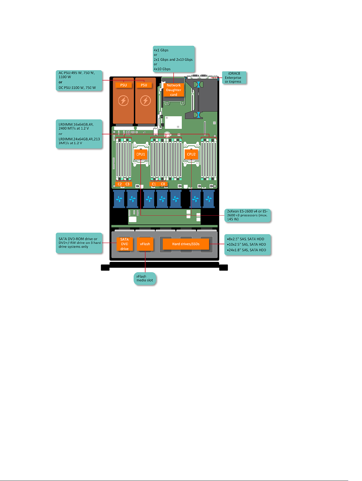
Figure 1. Supported configurations for the PowerEdge R630 system
Front panel
10
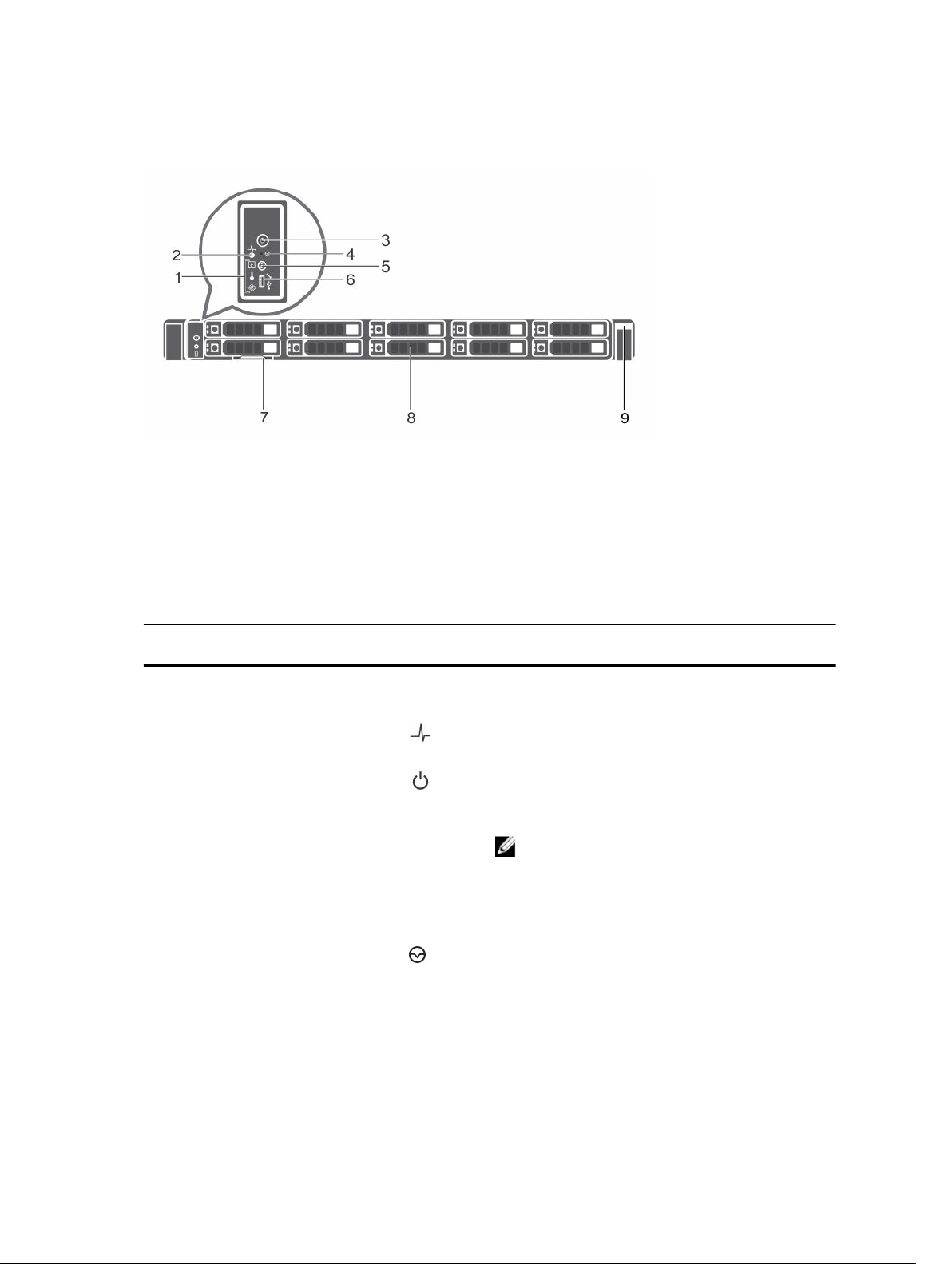
10 x 2.5-inch hard drive chassis
Figure 2. Front panel features of the 10 x 2.5-inch hard drive PowerEdge R630 chassis
1. Diagnostic indicators 2. System health indicator
3. Power-on indicator, power button 4. NMI button
5. System identification button 6. Micro USB port/iDRAC Direct
7. Information tag 8. Hard drives (10)
9. Quick Sync
Table 1. Front panel features of the 10 x 2.5-inch hard drive PowerEdge R630 chassis
Item Indicator, Button, or
Connector
Icon Description
1 Diagnostic indicators The diagnostic indicators light up to display error
status.
2 System health indicator The system health indicator flashes amber when a
system fault is detected.
3 Power-on indicator,
power button
The power indicator turns on when the system
power is on. The power button controls the power
supply output to the system.
NOTE: On ACPI-compliant operating systems,
turning off the system by using the power
button causes the system to perform a
graceful shutdown before power to the
system is turned off.
4 NMI button
Used to troubleshoot software and device driver
errors when running certain operating systems.
This button can be pressed by using the end of a
paper clip.
11

Item Indicator, Button, or
Connector
Icon Description
NOTE: Use this button only if directed to do
so by qualified support personnel or by the
operating system documentation.
5 System identification
button
The identification buttons on the front and back
panels can be used to locate a particular system
within a rack. When one of these buttons is
pressed, the system status indicator on the back
flashes until one of the buttons is pressed again.
Press to toggle the system ID on or off.
If the system stops responding during POST, press
and hold the system ID button for more than five
seconds to enter BIOS progress mode.
To reset the iDRAC (if not disabled in F2 iDRAC
setup), press and hold the button for more than 15
seconds.
6 Micro USB port/iDRAC
Direct
Enables you to connect USB devices to the system
or provides access to the iDRAC Direct features.
For more information, see the Integrated Dell
Remote Access Controller User's Guide at
Dell.com/idracmanuals. The port is USB 3.0-
compliant.
7 Information tag Contains system information such as service tag,
NIC, MAC address for your reference. The
information tag is a slide-out label panel.
8 Hard drives (10) Up to ten 2.5-inch hot swappable hard drives. Up
to six 2.5-inch hot swappable hard drives and up to
four 2.5-inch Dell PowerEdge Express Flash
devices (PCIe SSDs).
9 Quick Sync
Indicates a Quick Sync enabled system. The Quick
Sync feature is optional and needs a Quick Sync
bezel. This feature allows management of the
system by using mobile devices. This feature
aggregates hardware or firmware inventory and
various system level diagnostic and error
information that can be used in troubleshooting
the system. For more information, see the
Integrated Dell Remote Access Controller User’s
Guide at Dell.com/idracmanuals.
12
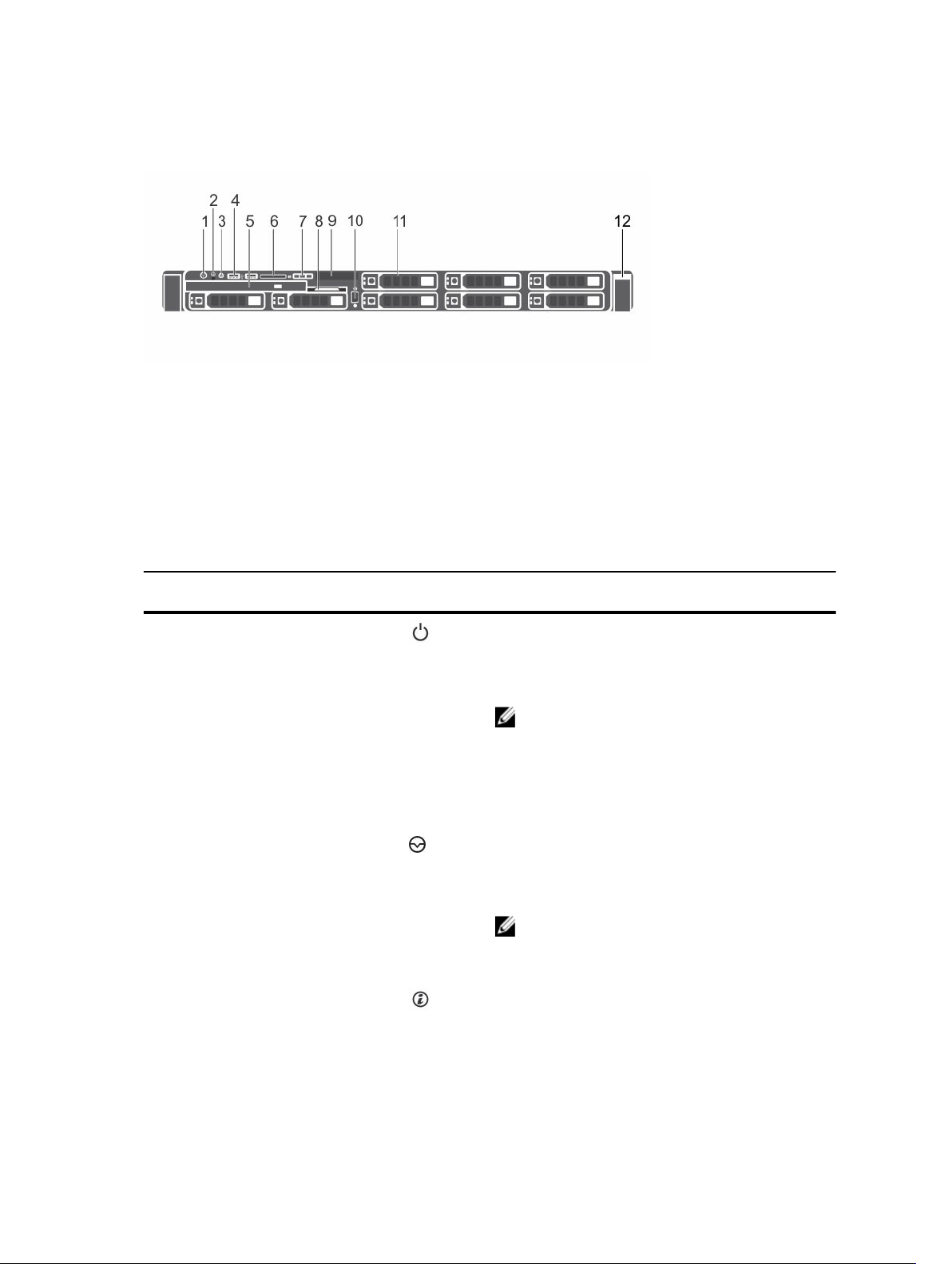
Eight x 2.5-inch hard drive chassis
Figure 3. Front panel features of the eight x 2.5-inch PowerEdge R630 hard drive chassis
1. Power-on indicator, power button 2. NMI button
3. System identification button 4. USB management port or iDRAC Direct (2)
5. Optical drive (optional) 6. SD vFlash media card slot
7. LCD menu buttons 8. Information tag
9. LCD panel 10. Video connector
11. Hard drives (8) 12. Quick Sync
Table 2. Front panel features of the eight x 2.5-inch PowerEdge R630 hard drive chassis
Item Indicator, Button, or
Connector
Icon Description
1 Power-on indicator,
power button
Enables you to know the power status of the
system. The power indicator turns on when the
system power is on. The power button controls
the power supply output to the system.
NOTE: On Advanced Configuration and
Power Interface (ACPI)-compliant operating
systems, turning off the system by using the
power button causes the system to perform a
graceful shutdown before power to the
system is turned off.
2 NMI button
Enables you to troubleshoot software and device
driver errors when running certain operating
systems. This button can be pressed by using the
end of a paper clip.
NOTE: Use this button only if directed to do
so by qualified support personnel or by the
operating system documentation.
3 System identification
button
Enables you to locate a particular system within a
rack. The identification buttons are on the front
and back panels. When one of these buttons is
pressed, the LCD panel on the front and the
13

Item Indicator, Button, or
Connector
Icon Description
system status indicator on the back flash until one
of the buttons is pressed again.
To turn the system ID on or off, press the system
identification button.
If the system stops responding during POST, press
and hold the system ID button for more than five
seconds to enter BIOS progress mode.
To reset the iDRAC (if not disabled in F2 iDRAC
setup), press and hold the button for more than 15
seconds.
4 USB management port/
iDRAC Direct (2)
Functions as a regular USB port or provides access
to the iDRAC Direct features. For more
information, see the iDRAC Guide at Dell.com/
idracmanuals.
The ports are USB 3.0-compliant.
5 Optical drive (optional) One optional SATA DVD-ROM drive or DVD+/-RW
drive.
NOTE: DVD devices are data only.
6 SD vFlash media card
slot
Enables you to insert a vFlash media card.
7 LCD menu buttons Enables you to navigate the control panel LCD
menu.
8 Information tag Contains system information such as service tag,
NIC, MAC address for your reference. The
information tag is a slide-out label panel.
9 LCD panel Displays system ID, status information, and system
error messages. The LCD turns blue during normal
system operation. When the system needs
attention, the LCD turns amber and the LCD panel
displays an error code followed by descriptive text.
NOTE: If the system is connected to AC
power and an error is detected, the LCD turns
amber regardless of whether the system is
turned on or off.
10 Video connector Enables you to connect a VGA display to the
system.
11 Hard drives (8) Up to eight 2.5-inch hot swappable hard drives.
12. Quick Sync
Indicates a Quick Sync enabled system. The Quick
Sync feature is optional and needs a Quick Sync
14
Item Indicator, Button, or
Connector
Icon Description
bezel. This feature allows management of the
system by using mobile devices. This feature
aggregates hardware or firmware inventory and
various system level diagnostic and error
information that can be used in troubleshooting
the system. For more information, see the
Integrated Dell Remote Access Controller User’s
Guide at Dell.com/idracmanuals.
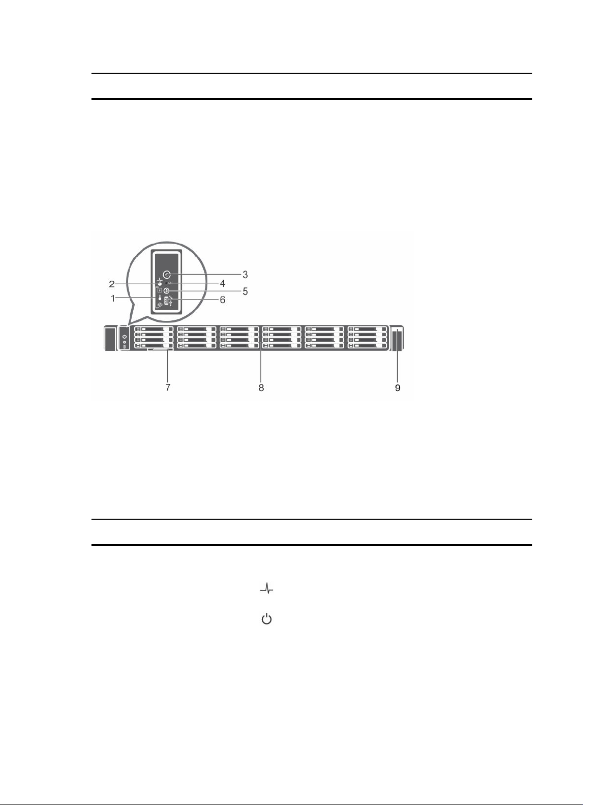
24 x 1.8-inch hard drive chassis
Figure 4. Front panel features of the 24 x 1.8-inch hard drive PowerEdge R630 chassis
1. Diagnostic indicators 2. System health indicator
3. Power-on indicator, power button 4. NMI button
5. System identification button 6. Micro USB port
7. Information tag 8. Hard drives (24)
9. Quick Sync
Table 3. Front panel features of the 24 x 1.8-inch hard drive PowerEdge R630 chassis
Item Indicator, Button, or
Connector
Icon Description
1 Diagnostic indicators The diagnostic indicators light up to display error
status.
2 System health indicator The system health indicator flashes amber when a
system fault is detected.
3 Power-on indicator,
power button
The power indicator turns on when the system
power is on. The power button controls the
power supply output to the system.
15

Item Indicator, Button, or
Connector
Icon Description
NOTE: On ACPI-compliant operating
systems, turning off the system by using the
power button causes the system to perform
a graceful shutdown before power to the
system is turned off.
4 NMI button
Used to troubleshoot software and device driver
errors when running certain operating systems.
This button can be pressed by using the end of a
paper clip.
NOTE: Use this button only if directed to do
so by qualified support personnel or by the
operating system documentation.
5 System identification
button
The identification buttons on the front and back
panels can be used to locate a particular system
within a rack. When one of these buttons is
pressed, the system status indicator on the back
flashes until one of the buttons is pressed again.
Press to toggle the system ID on or off.
If the system stops responding during POST, press
and hold the system ID button for more than five
seconds to enter BIOS progress mode.
To reset the iDRAC (if not disabled in F2 iDRAC
setup), press and hold the button for more than
15 seconds.
6 Micro USB port Enables you to connect USB devices to the
system or provides access to the iDRAC Direct
features. For more information, see the Integrated
Dell Remote Access Controller User's Guide at
Dell.com/idracmanuals. The port is USB 3.0-
compliant.
7 Information tag Contains system information such as service tag,
NIC, MAC address for your reference. The
information tag is a slide-out label panel.
8 Hard drives (24) Up to twenty four 1.8-inch hot swappable hard
drives.
9 Quick Sync
Indicates a Quick Sync enabled system. The
Quick Sync feature is optional and needs a Quick
Sync bezel. This feature allows management of
the system by using mobile devices. This feature
aggregates hardware or firmware inventory and
various system level diagnostic and error
information that can be used in troubleshooting
the system. For more information, see the
16
Item Indicator, Button, or
Connector
Icon Description
Integrated Dell Remote Access Controller User’s
Guide at Dell.com/idracmanuals.
LCD panel
The LCD panel of your system provides system information, status, and error messages to indicate if the
system is functioning correctly or if the system needs attention. For more information about error
messages, see the Dell Event and Error Messages Reference Guide at Dell.com/
openmanagemanuals >OpenManage software.
• The LCD backlight turns blue during normal operating conditions.
• When the system needs attention, the LCD turns amber, and displays an error code followed by
descriptive text.
NOTE: If the system is connected to a power source and an error is detected, the LCD turns
amber regardless of whether the system is turned on or off.
• The LCD backlight is turned off when the system is in standby mode and can be turned on by pressing
either the Select, Left, or Right button on the LCD panel.
• The LCD backlight remains off if LCD messaging is turned off using the iDRAC utility, the LCD panel,
or other tools.
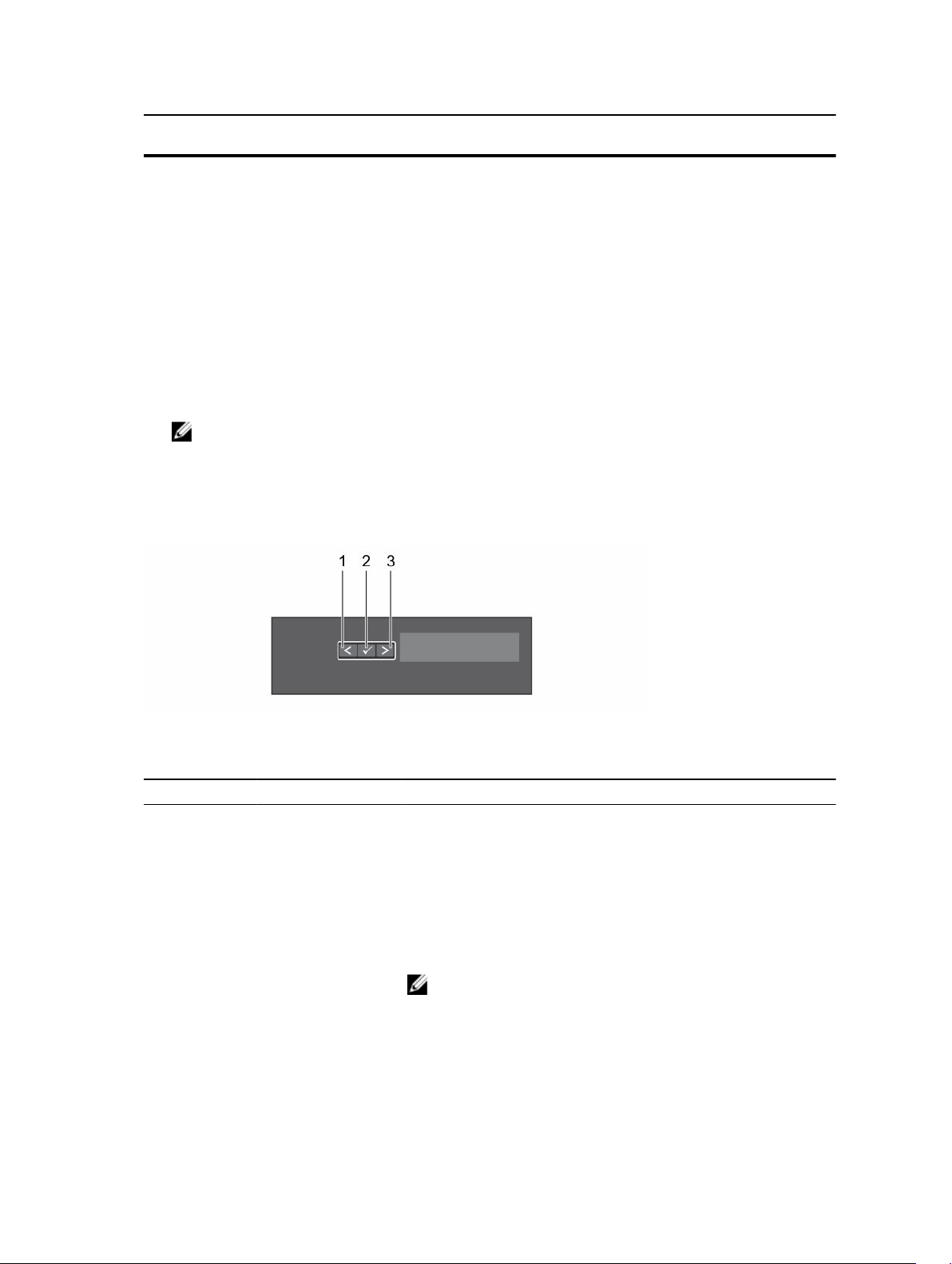
Figure 5. LCD panel features
Table 4. LCD panel features
Item Button Description
1 Left Moves the cursor back in one-step increments.
2 Select Selects the menu item highlighted by the cursor.
3 Right Moves the cursor forward in one-step increments.
During message scrolling:
• Press and hold the button to increase scrolling speed.
• Release the button to stop.
NOTE: The display stops scrolling when the button is
released. After 45 seconds of inactivity the display starts
scrolling.
17

Viewing Home screen
About this task
The Home screen displays user-configurable information about the system. This screen is displayed
during normal system operation when there are no status messages or errors. When the system is in
standby mode, the LCD backlight turns off after a few minutes of inactivity, if there are no error
messages.
Steps
1. To view the Home screen, press one of the three navigation buttons (Select, Left, or Right).
2. To navigate to the Home screen from another menu, complete the following steps:
a. Press and hold the up arrow until the Home icon is displayed.
b. Select the Home icon.
c. On the Home screen, press the Select button to enter the main menu.
Setup menu
NOTE: When you select an option in the Setup menu, you must confirm the option before
proceeding to the next action.
Option Description
iDRAC Select DHCP or Static IP to configure the network mode. If Static IP is selected,
the available fields are IP, Subnet (Sub), and Gateway (Gtw). Select Setup DNS to
enable DNS and to view domain addresses. Two separate DNS entries are available.
Set error Select SEL to view LCD error messages in a format that matches the IPMI
description in the SEL. This enables you to match an LCD message with an SEL
entry.
Select Simple to view LCD error messages in a simplified user-friendly description.
For more information about error messages, see the Dell Event and Error Messages
Reference Guide at Dell.com/openmanagemanuals > OpenManage software.
Set home Select the default information to be displayed on the Home screen. See View menu
section for the options and option items that can be set as the default on the
Home screen.
Related Links
View menu
View menu
NOTE: When you select an option in the View menu, you must confirm the option before
proceeding to the next action.
Option Description
iDRAC IP Displays the IPv4 or IPv6 addresses for iDRAC8. Addresses include DNS (Primary
and Secondary), Gateway, IP, and Subnet (IPv6 does not have Subnet).
MAC Displays the MAC addresses for iDRAC, iSCSI, or Network devices.
Name Displays the name of the Host, Model, or User String for the system.
Number Displays the Asset tag or the Service tag for the system.
18
Option Description
Power Displays the power output of the system in BTU/hr or Watts. The display format can
be configured in the Set home submenu of the Setup menu.
Temperature Displays the temperature of the system in Celsius or Fahrenheit. The display format
can be configured in the Set home submenu of the Setup menu.
Back panel
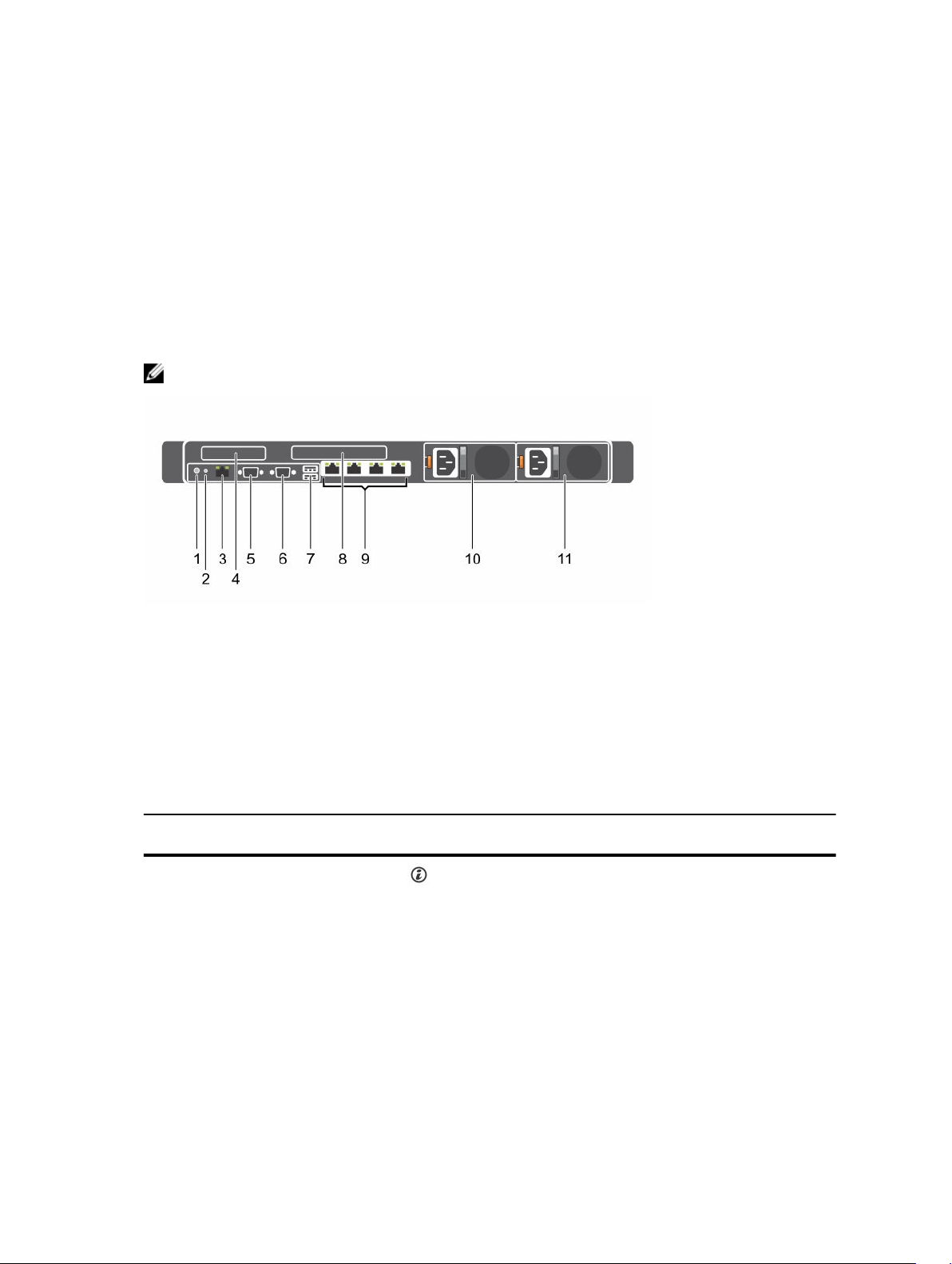
Two-riser chassis
NOTE: This is only applicable for eight x 2.5-inch hard drive chassis.
Figure 6. Back panel features (two PCIe expansion cards)
1. System identification button 2. System identification connector
3. iDRAC8 Enterprise port 4. PCIe expansion card slot (riser 1)
5. Serial connector 6. Video connector
7. USB ports (2) 8. PCIe expansion card slot (riser 2)
9. Ethernet connectors (4) 10. Power supply unit (PSU1)
11. Power supply unit (PSU2)
Table 5. Back panel features (two PCIe expansion cards)
Item Indicator, Button, or
Connector
Icon Description
1 System identification
button
The identification buttons on the front and back
panels can be used to locate a particular system
within a rack. When one of these buttons is
pressed, the LCD panel on the front and the
system status indicator on the back flash until one
of the buttons is pressed again.
Press to toggle the system ID on and off. If the
system stops responding during POST, press and
hold the system ID button for more than five
seconds to enter BIOS progress mode.
19

Item Indicator, Button, or
Connector
Icon Description
To reset iDRAC (if not disabled in F2 iDRAC setup),
press and hold for more than 15 seconds.
2 System identification
connector
Enables you to connect the optional system status
indicator assembly through the optional cable
management arm.
3 iDRAC8 Enterprise port Dedicated management port.
NOTE: The port is available for use only if the
iDRAC8 Enterprise license is installed on your
system.
4 PCIe expansion card slot
(riser 1)
Enables you to connect a low profile PCIe
expansion card. See the Expansion card installation
guidelines section.
5 Serial connector Enables you to connect a serial device to the
system.
6 Video connector Enables you to connect a VGA display to the
system.
7 USB ports (2) Enables you to connect USB devices to the system.
The ports are USB 3.0-compliant.
8 PCIe expansion card slot
(riser 2)
Enables you to connect a full height three-fourth
length PCIe expansion card. See the Expansion
card installation guidelines section.
9 Ethernet connectors (4) Four integrated 10/100/1000 Mbps NIC
connectors
or
Four integrated connectors:
• Two integrated 10/100/1000 Mbps NIC
connectors
• Two integrated 100 Mbps/1 Gbps/10 Gbps SFP
+ connectors
or
• Four 10 Gbps
10 PSU1
• Two 495 W, 750 W, or 1100 W AC power supply
units (PSUs)
Or
• Two 1100 W DC PSUs
Or
• Two 750 W mixed mode PSUs
11 PSU2
• Two 495 W, 750 W, or 1100 W AC PSUs
Or
• Two 1100 W DC PSUs
20
Item Indicator, Button, or
Connector
Icon Description
Or
• Two 750 W mixed mode PSUs
Related Links
Expansion card installation guidelines
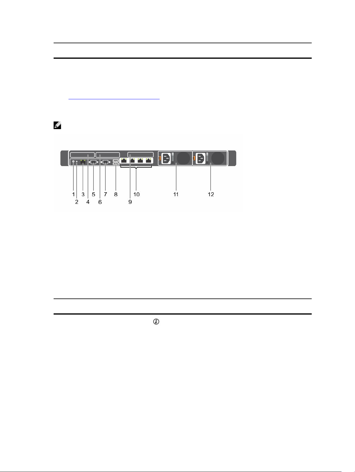
Three-riser chassis
NOTE: This is applicable for eight x 2.5-inch, 10 x 2.5-inch, or 24 x 1.8-inch hard drive chassis.
Figure 7. Back panel features (three PCIe expansion cards)
1. System identification button 2. System identification connector
3. pci 4. iDRAC8 Enterprise port
5. LP PCIe expansion card slot (riser 1) 6. Serial connector
7. LP PCIe expansion card slot (riser 2) 8. Video connector
9. USB port (2) 10. LP PCIe expansion card slot (riser 3)
11. Ethernet connectors (4) 12. Power supply (PSU1)
13. Power supply (PSU2)
Table 6. Back panel features (three PCIe expansion cards)
Item Indicator, Button, or
Connector
Icon Description
1 System identification
button
The identification buttons on the front and back
panels can be used to locate a particular system
within a rack.
10/24 hard drive
system
When one of these buttons
is pressed, the system status
indicator on the back
flashes until one of the
buttons is pressed again.
Eight hard drive
system
When one of these buttons
is pressed, the LCD panel
on the front and the system
21

Item Indicator, Button, or
Connector
Icon Description
status indicator on the back
flashes until one of the
buttons is pressed again.
Press to toggle the system ID on and off. If the
system stops responding during POST, press and
hold the system ID button for more than five
seconds to enter BIOS progress mode.
To reset iDRAC (if not disabled in F2 iDRAC setup)
press and hold for more than 15 seconds.
2 System identification
connector
Enables you to connect the optional system status
indicator assembly through the optional cable
management arm.
3 iDRAC8 Enterprise port Dedicated management port.
NOTE: The port is available for use only if the
iDRAC8 Enterprise license is installed on your
system.
4 LP PCIe expansion card
slot (riser 1)
Enables you to connect a low profile LP PCIe
expansion card. See the Expansion card installation
guidelines section.
5 Serial connector Enables you to connect a serial device to the
system.
6 LP PCIe expansion card
slot (riser 2)
Enables you to connect a low profile LP PCIe
expansion card. See the Expansion card installation
guidelines section.
7 Video connector Enables you to connect a VGA display to the
system.
8 USB port (2) Enables you to connect USB devices to the system.
The ports are USB 3.0-compliant.
9 LP PCIe expansion card
slot (riser 3)
Enables you to connect a LP PCIe expansion card.
See the Expansion card installation guidelines
section.
10 Ethernet connectors (4) Four integrated 10/100/1000 Mbps NIC
connectors
or
Four integrated connectors:
• Two integrated 10/100/1000 Mbps NIC
connectors
• Two integrated 100 Mbps/1 Gbps/10 Gbps SFP
+ connectors
22

Item Indicator, Button, or
Connector
Icon Description
or
• Four 10 Gbps
11 PSU1
• Two 495 W, 750 W, or 1100 W AC power supply
units (PSUs)
Or
• Two 1100 W DC PSUs
Or
• Two 750 W mixed mode PSUs
12 PSU2
• Two 495 W, 750 W, or 1100 W AC PSUs
Or
• Two 1100 W DC PSUs
Or
• Two 750 W mixed mode PSUs
Related Links
Expansion card installation guidelines
Diagnostic indicators
The diagnostic indicators on the system front panel display system status during system startup.
NOTE: The diagnostic indicators are not present if the system is equipped with an LCD display.
NOTE: The diagnostic indicators are present only on the 10 hard drive and the 24 hard drive
systems.
NOTE: No diagnostic indicators are lit when the system is turned off. To start the system, plug it into
a working power source and press the power button.
Table 7. Diagnostic indicators
Icon Description Condition Corrective action
Health
indicator
The indicator turns solid
blue if the system is in good
health.
None required.
The indicator flashes amber:
• When the system is
turned on.
• When the system is in
standby.
• If any error condition
exists. For example, a
failed fan, PSU, or a hard
drive.
Check the System Event Log or system
messages for the specific issue. For more
information about error messages, see the
Dell Event and Error Messages Reference
Guide at Dell.com/openmanagemanuals >
OpenManage software.
The POST process is interrupted without
any video output due to invalid memory
configurations. See the Getting help
section.
23

Icon Description Condition Corrective action
Hard drive
indicator
The indicator flashes amber
if there is a hard drive error.
Check the System Event Log to determine
the hard drive that has an error. Run the
appropriate Online Diagnostics test. Restart
the system and run embedded diagnostics
(ePSA). If the hard drives are configured in a
RAID array, restart the system and enter the
host adapter configuration utility program.
Electrical
indicator
The indicator flashes amber
if the system experiences an
electrical error (for example,
voltage out of range, or a
failed power supply unit
(PSU) or voltage regulator).
Check the System Event Log or system
messages for the specific issue. If it is due
to a problem with the PSU, check the LED
on the PSU. Reseat the PSU. If the problem
persists, see the Getting help section.
Temperature
indicator
The indicator flashes amber
if the system experiences a
thermal error (for example,
the ambient temperature is
out of range or fan failure).
Ensure that none of the following
conditions exist:
• A cooling fan has been removed or has
failed.
• System cover, cooling shroud, EMI filler
panel, memory module blank, or back
filler bracket is removed.
• Ambient temperature is too high.
• External airflow is obstructed.
See the Getting help section.
Memory
indicator
The indicator flashes amber
if a memory error occurs.
Check the system event log or system
messages for the location of the failed
memory. Reseat the memory module. If
the problem persists, see the Getting help
section.
PCIe indicator The indicator flashes amber
if a PCIe card experiences
an error.
Restart the system. Update any required
drivers for the PCIe card. Reinstall the card.
If the problem persists, see the Getting help
section.
NOTE: For more information on
supported PCIe cards, see the
Expansion card installation guidelines
section.
Related Links
Getting help
Expansion card installation guidelines
24
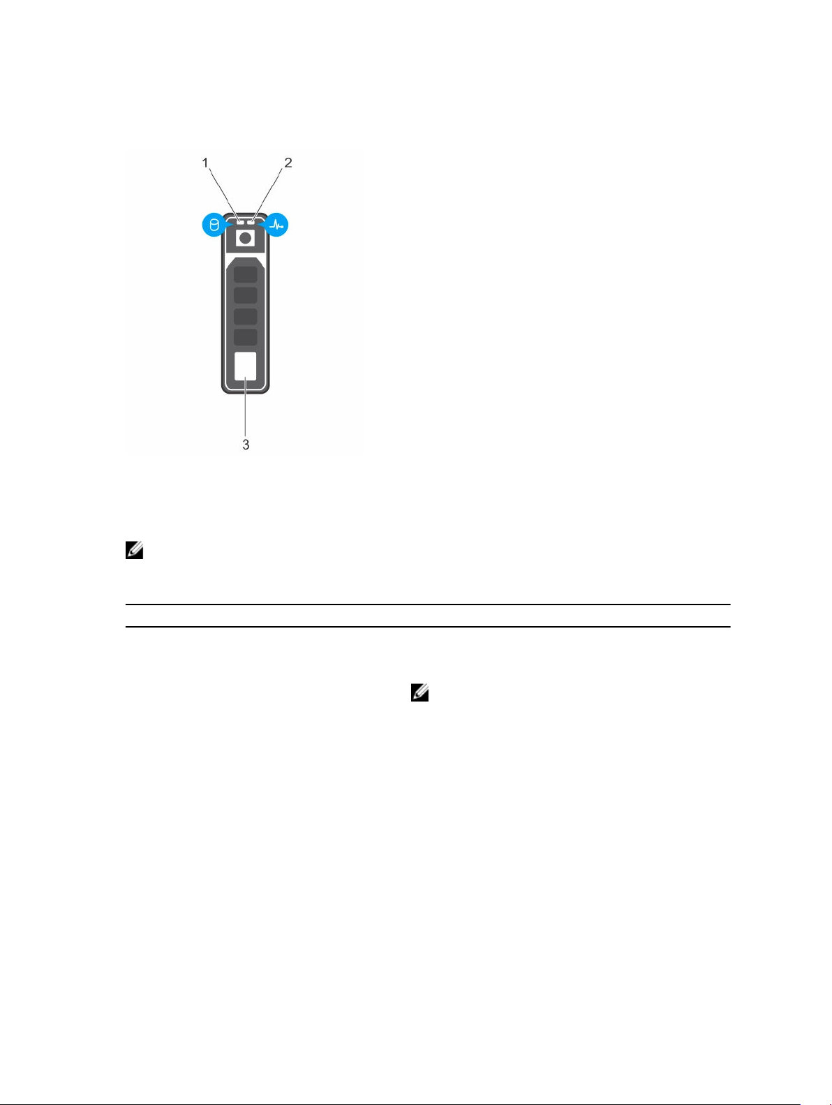
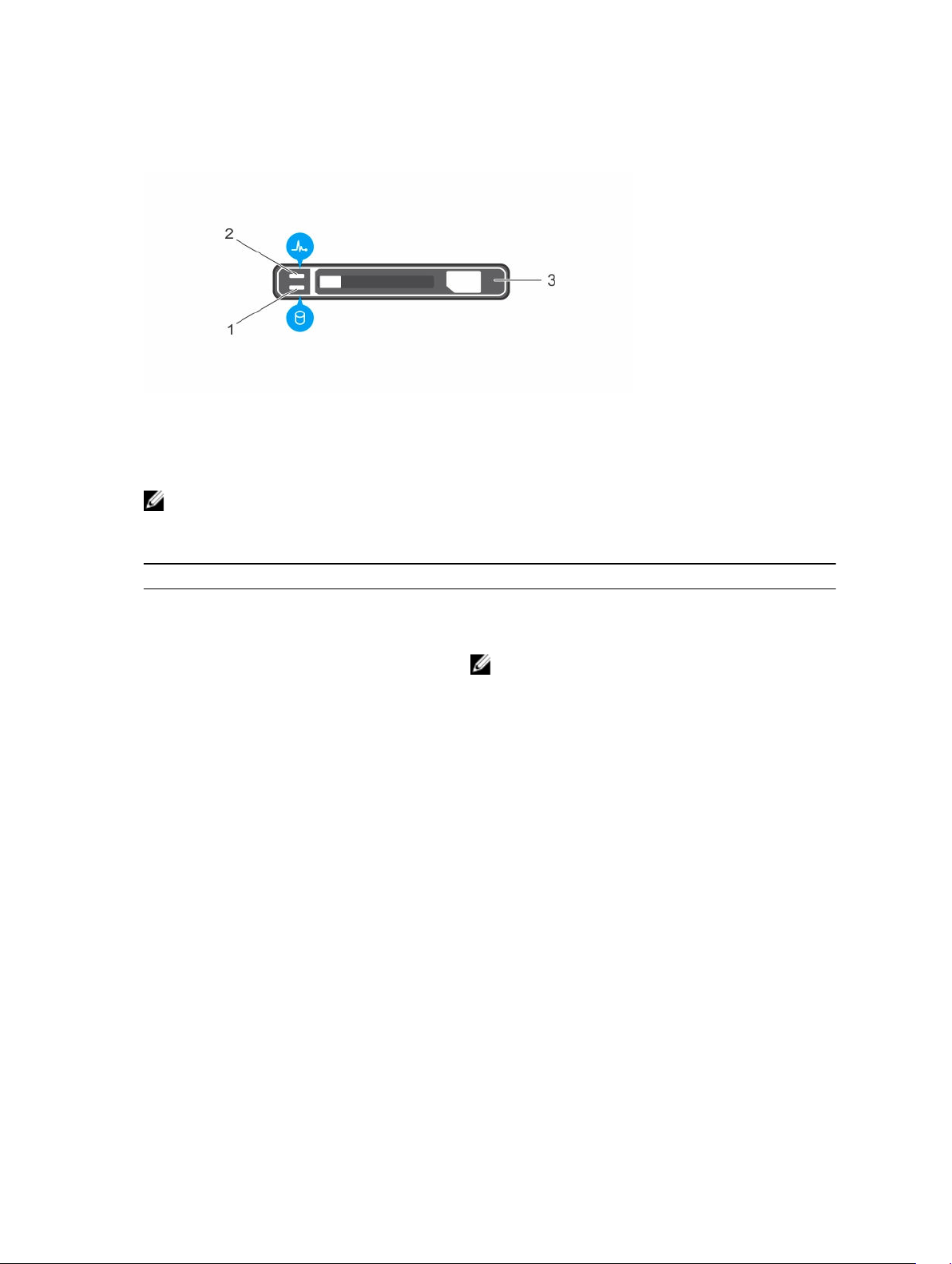
Hard drive indicator codes
Figure 8. Hard drive indicators
1. hard drive activity indicator 2. hard drive status indicator
3. hard drive
NOTE: If the hard drive is in the Advanced Host Controller Interface (AHCI) mode, the status
indicator (on the right side) does not function and remains off.
Table 8. Hard drive indicator codes
Drive-status indicator pattern (RAID only) Condition
Flashes green twice per second Identifying drive or preparing for removal.
Off Drive ready for insertion or removal.
NOTE: The drive status indicator remains off until
all hard drives are initialized after the system is
turned on. Drives are not ready for insertion or
removal during this time.
Flashes green, amber, and turns off Predicted drive failure
Flashes amber four times per second Drive failed
Flashes green slowly Drive rebuilding
Steady green Drive online
Flashes green for three seconds, amber for
three seconds, and turns off after six seconds
Rebuild stopped
25
uSATA SSD indicator codes
Figure 9. uSATA SSD indicators
1. uSATA SSD activity indicator 2. uSATA SSD status indicator
3. uSATA SSD
NOTE: If the SSD is in the Advanced Host Controller Interface (AHCI) mode, the status indicator (on
the right side) does not function and remains off.
Table 9. Drive status indicator codes
Drive-status indicator pattern Condition
Flashes green twice per second Identifying drive or preparing for removal.
Off Drive ready for insertion or removal.
NOTE: The drive status indicator remains off until
all hard drives are initialized after the system is
turned on. Drives are not ready for insertion or
removal during this time.
Flashes green, amber, and turns off Predicted drive failure
Flashes amber four times per second Drive failed
Steady green Drive online
Flashes green for three seconds, amber for
three seconds, and turns off after six seconds
Rebuild aborted
26
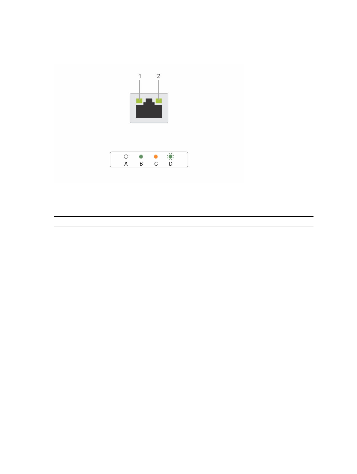
NIC indicator codes
Figure 10. NIC indicators
1. link indicator 2. activity indicator
Table 10. NIC indicators
Convention Status Condition
A Link and activity indicators are off The NIC is not connected to the
network.
B Link indicator is green The NIC is connected to a valid network
at its maximum port speed (1 Gbps or 10
Gbps).
C Link indicator is amber The NIC is connected to a valid network
at less than its maximum port speed.
D Activity indicator is flashing green Network data is being sent or received.
Power supply unit indicator codes
AC power supply units (PSUs) have an illuminated translucent handle that serves as an indicator and DC
PSUs have an LED that serves as an indicator. The indicator shows whether power is present or a power
fault has occurred.
27
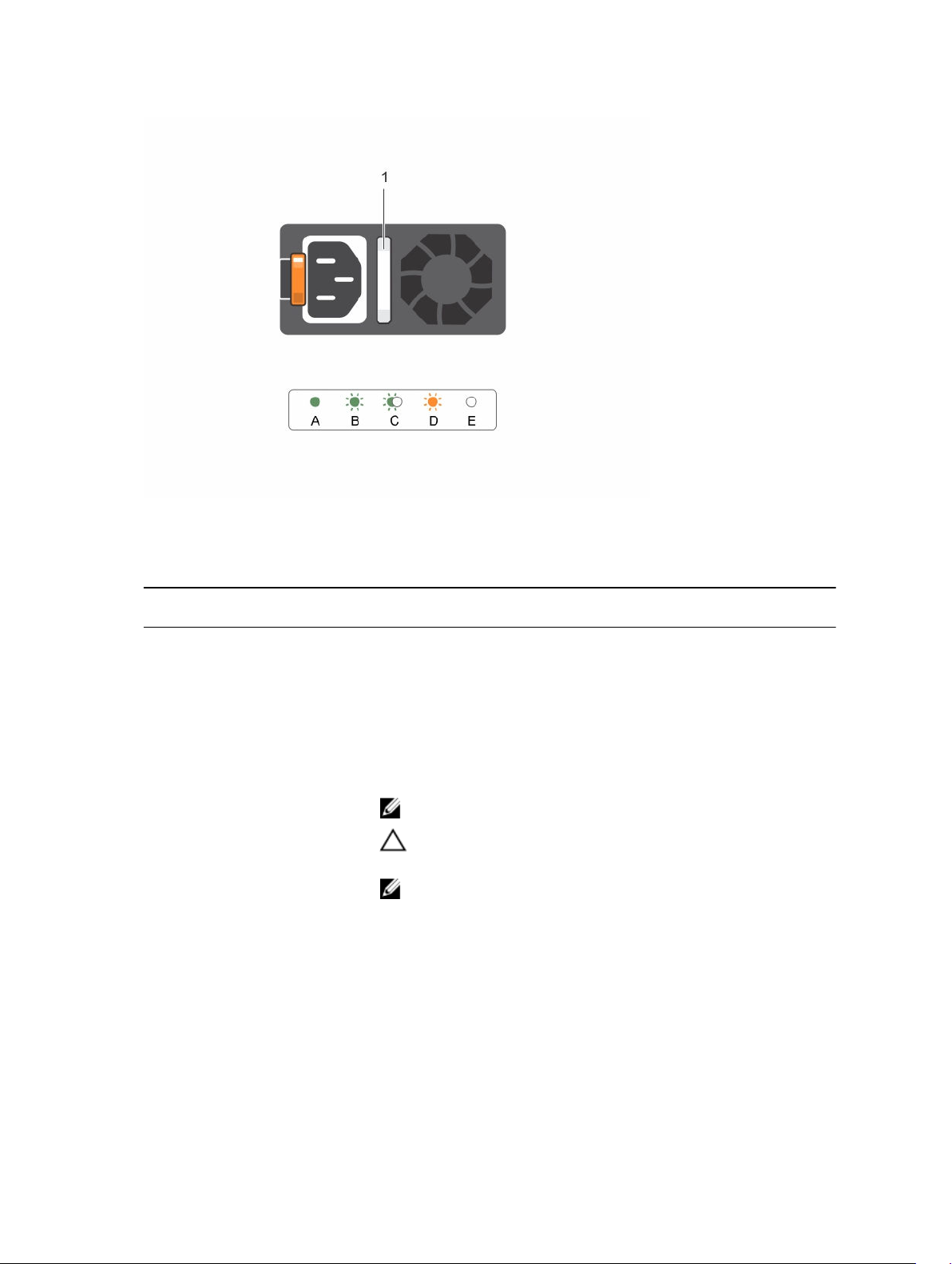
Figure 11. AC PSU status indicator
1. AC PSU status indicator/handle
Table 11. AC PSU status indicators
Convention Power indicator
pattern
Condition
A Green A valid power source is connected to the PSU and the PSU is
operational.
B Flashing green When the firmware of the PSU is being updated, the PSU handle
flashes green.
C Flashing green
and turns off
When hot-adding a PSU, the PSU handle flashes green five times at
4 Hz rate and turns off. This indicates a PSU mismatch with respect
to efficiency, feature set, health status, and supported voltage.
NOTE: Ensure that both the PSUs are of the same capacity.
CAUTION: For AC PSUs, use only PSUs with the Extended
Power Performance (EPP) label on the back.
NOTE: Mixing PSUs from previous generations of Dell
PowerEdge servers can result in a PSU mismatch condition or
failure to turn the system on.
D Flashing amber Indicates a problem with the PSU.
28
Convention Power indicator
pattern
Condition
CAUTION: When correcting a PSU mismatch, replace only the
PSU with the flashing indicator. Swapping the PSU to make a
matched pair can result in an error condition and unexpected
system shutdown. To change from a high output
configuration to a low output configuration or vice versa, you
must power down the system.
CAUTION: AC PSUs support both 220 V and 110 V input
voltages with the exception of Titanium PSUs, which support
only 220 V. When two identical PSUs receive different input
voltages, they can output different wattages, and trigger a
mismatch.
CAUTION: If two PSUs are used, they must be of the same type
and have the same maximum output power.
CAUTION: Combining AC and DC PSUs is not supported and
triggers a mismatch.
E Not lit Power is not connected.
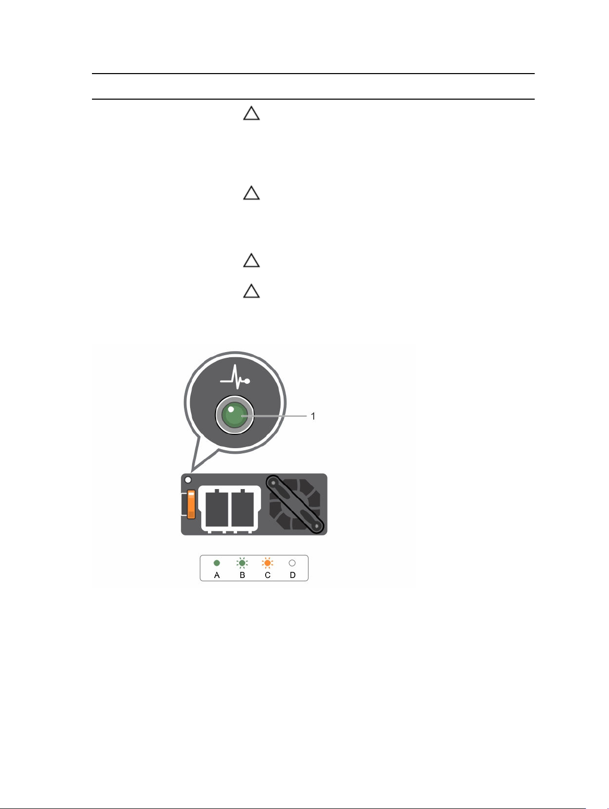
Figure 12. DC PSU status indicator
1. DC PSU status indicator
29

Table 12. DC PSU status indicators
Convention Power indicator
pattern
Condition
A Green A valid power source is connected to the PSU and that the PSU is
operational.
B Flashing green When hot-adding a PSU, the PSU indicator flashes green. This
indicates that there is a PSU mismatch with respect to efficiency,
feature set, health status, and supported voltage. Ensure that both
the PSUs are of the same capacity.
C Flashing amber Indicates a problem with the PSU.
CAUTION: When correcting a PSU mismatch, replace only
the PSU with the flashing indicator. Swapping the PSU to
make a matched pair can result in an error condition and
unexpected system shutdown. To change from a High
Output configuration to a Low Output configuration or vice
versa, you must power down the system.
CAUTION: AC PSU support both 220 V and 110 V input
voltages with the exception of Titanium PSU, which support
only 220 V. When two identical PSU receive different input
voltages, they can output different wattages, and trigger a
mismatch.
CAUTION: If two PSU are used, they must be of the same
type and have the same maximum output power.
CAUTION: Combining AC and DC PSU is not supported and
triggers a mismatch.
D Not lit Power is not connected.
iDRAC Direct LED indicator codes
NOTE: The iDRAC Direct LED indicator does not turn on when the USB port is used in the USB
mode.
30
Loading...