


 Loading...
Dell SC5020 Storage System
Owner’s Manual

Notes, Cautions, and Warnings
NOTE: A NOTE indicates important information that helps you make better use of your product.
CAUTION: A CAUTION indicates either potential damage to hardware or loss of data and tells you how to avoid the problem.
WARNING: A WARNING indicates a potential for property damage, personal injury, or death.
Copyright © 2017 Dell Inc. or its subsidiaries. All rights reserved. Dell, EMC, and other trademarks are trademarks of Dell Inc. or its subsidiaries. Other trademarks may be trademarks of their respective owners.
2017 - 06
Rev. A

Contents |
|
About This Manual............................................................................................................. |
5 |
Revision History.................................................................................................................................................................. |
5 |
Audience............................................................................................................................................................................ |
5 |
Contacting Dell................................................................................................................................................................... |
5 |
1 SC5020 Storage System Hardware................................................................................. |
6 |
SC5020 Storage System Front-Panel Features and Indicators........................................................................................... |
6 |
SC5020 Storage System Back-Panel Features and Indicators............................................................................................ |
7 |
SC5020 Storage System Drives......................................................................................................................................... |
8 |
SC5020 Storage System Drive Numbering......................................................................................................................... |
8 |
SC5020 Storage Controller Features and Indicators .......................................................................................................... |
9 |
SC5020 Storage Controller.......................................................................................................................................... |
9 |
2 Replacing SC5020 Storage System Components.......................................................... |
12 |
Safety Precautions............................................................................................................................................................ |
12 |
Installation Safety Precautions.................................................................................................................................... |
12 |
Electrical Safety Precautions....................................................................................................................................... |
12 |
Electrostatic Discharge Precautions............................................................................................................................ |
13 |
General Safety Precautions......................................................................................................................................... |
13 |
Bezel................................................................................................................................................................................. |
13 |
Remove the Front Bezel.............................................................................................................................................. |
13 |
Install the Front Bezel.................................................................................................................................................. |
14 |
Hard Drives ...................................................................................................................................................................... |
14 |
Identify the Failed Drive............................................................................................................................................... |
14 |
Remove the Failed Drive............................................................................................................................................. |
15 |
Install the Replacement Drive...................................................................................................................................... |
15 |
Power Supply/Cooling Fan Modules................................................................................................................................. |
15 |
Identify the Failed Power Supply................................................................................................................................. |
15 |
Identify the Failed Cooling Fan.................................................................................................................................... |
16 |
Replace a Power Supply/Cooling Fan Module............................................................................................................. |
16 |
Storage Controllers............................................................................................................................................................ |
17 |
Before Working Inside an SC5020 Storage Controller................................................................................................. |
18 |
Storage Controller Service Baffle................................................................................................................................ |
18 |
Storage Controller....................................................................................................................................................... |
19 |
Storage Controller Cover............................................................................................................................................. |
21 |
Battery Backup Unit................................................................................................................................................... |
23 |
Riser 1......................................................................................................................................................................... |
24 |
I/O Card..................................................................................................................................................................... |
26 |
Mezzanine Card......................................................................................................................................................... |
29 |
Rack Rails......................................................................................................................................................................... |
32 |
Remove the Rack Rails............................................................................................................................................... |
32 |
Install the Rack Rails................................................................................................................................................... |
32 |
3

Power Up the Storage Center Hardware.......................................................................................................................... |
33 |
3 SC5020 Storage System Technical Specifications........................................................ |
34 |
Technical Specifications.................................................................................................................................................... |
34 |
4

About This Manual
This manual describes the features and technical specifications of an SC5020 storage system.
Revision History
Document Number: 680-138-001
Revision |
Date |
Description |
|
|
|
A |
June 2017 |
Initial release |
Audience
The information provided in this manual is intended for use by Dell end users.
Contacting Dell
Dell provides several online and telephone-based support and service options. Availability varies by country and product, and some services might not be available in your area.
To contact Dell for sales, technical support, or customer service issues, go to www.dell.com/support.
•For customized support, type your system service tag on the support page and click Submit.
•For general support, browse the product list on the support page and select your product.
About This Manual |
5 |

1
SC5020 Storage System Hardware
The SC5020 storage system ships with Dell Enterprise drives, two redundant power supply/cooling fan modules, and two redundant storage controllers.
Each storage controller contains the front-end, back-end, and management communication ports of the storage system.
SC5020 Storage System Front-Panel Features and Indicators
The front panel of the SC5020 contains power and status indicators, and a system identification button. In addition, the hard drives are installed and removed through the front of the storage system chassis.
Figure 1. SC5020 Storage System Front-Panel View
Item |
Name |
Icon |
Description |
|
|
|
|
1 |
Power indicator |
|
Lights when the storage system power is on |
|
|
|
• O„ – No power |
|
|
|
• On steady green – At least one power supply is providing power to the |
|
|
|
storage system |
|
|
|
|
2 |
Status indicator |
|
Lights when at least one power supply is supplying power to the storage |
|
|
|
system |
|
|
|
• O„ – No power |
|
|
|
• On steady blue – Power is on and firmware is running |
|
|
|
• Blinking amber – Fault detected |
|
|
|
|
3 |
Identification button |
|
Blinking blue continuously – A user sent a command to the storage system to |
|
|
|
make the LED blink so that the user can identify the storage system in the |
|
|
|
rack. |
|
|
|
• The identification LED blinks on the control panel of the chassis, to allow |
|
|
|
users to find the storage system when looking at the front of the rack. |
|
|
|
|
6 |
SC5020 Storage System Hardware |
Item |
Name |
Icon |
Description |
|
|
|
|
|
|
|
• The identification LEDs on the storage controllers also blink, which allows |
|
|
|
users to find the storage system when looking at the back of the rack. |
|
|
|
|
4 |
Hard drives |
— |
Can have up to 30 internal 2.5-inch SAS hard drives |
|
|
|
|
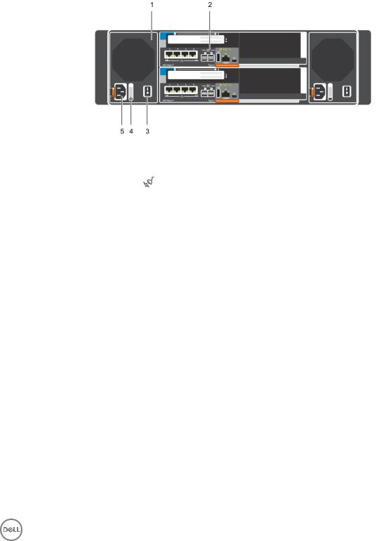
SC5020 Storage System Back-Panel Features and Indicators
The back panel of the SC5020 contains the storage controller indicators and power supply indicators.
Figure 2. SC5020 Storage System Back-Panel View
Item |
Name |
Icon |
Description |
|
|
|
|
|
|
1 |
Power supply/cooling |
|
Contains a 1485 W power supply and fans that provide cooling for the storage |
|
|
fan module (2) |
|
system, with AC input to the power supply of 200–240 V. In Dell Storage |
|
|
|
|
Manager, the power supply/cooling fan module on the left side of the back |
|
|
|
|
panel is Power Supply 1 and power supply/cooling fan module on the right side |
|
|
|
|
of the back panel is Power Supply 2. |
|
|
|
|
An LED behind the LED handle indicates whether the power supply has AC/ |
|
|
|
|
input power. |
|
|
|
|
• Green – A valid power source is connected to the power supply and the |
|
|
|
|
power supply is operational. |
|
|
|
|
• Not lit – The power supply is o„ or the power source has a fault. |
|
|
|
|
|
|
2 |
Storage controller (2) |
— |
Each storage controller contains: |
|
|
|
|
• Mezzanine card with four SFP+ ports or four RJ45 10GBASE-T ports |
|
|
|
|
• One expansion slot a front-end I/O card: |
|
|
|
|
– |
Fibre Channel |
|
|
|
– |
iSCSI |
|
|
|
– |
SAS |
|
|
|
• SAS expansion ports – Two 12 Gbps SAS ports for back-end connectivity |
|
|
|
|
to expansion enclosures |
|
|
|
|
• USB port – Single USB 2.0 port |
|
|
|
|
• MGMT port – Embedded Ethernet port for system management |
|
|
|
|
• Serial port – Micro-USB serial port used for an alternative initial |
|
|
|
|
configuration and support-only functions |
|
|
|
|
|
|
3 |
Power switch (2) |
— |
Controls power for the storage system. Each power supply/cooling fan module |
|
|
|
|
has one power switch. |
|
|
|
|
|
|
SC5020 Storage System Hardware |
7 |
Item |
Name |
Icon |
Description |
|
|
|
|
4 |
Power supply/cooling |
— |
The handle of the power supply/cooling fan module indicates the DC power |
|
fan module LED handle |
|
status of the power supply and the fans. |
|
|
|
• Not lit – No power |
|
|
|
• Solid green – Power supply has valid power source and is operational |
|
|
|
• Blinking amber – Error condition in the power supply |
|
|
|
• Blinking green – Firmware is being updated. |
|
|
|
• Blinking green then o„ – Power supply mismatch |
|
|
|
|
5 |
Power socket (2) |
— |
Accepts the following standard computer power cords: |
|
|
|
• IEC320-C13 for deployments worldwide |
|
|
|
• IEC60320-C19 for deployments in Japan |
|
|
|
|
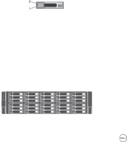
SC5020 Storage System Drives
The SC5020 storage system supports Dell Enterprise Plus Premium drives.
The drives in the SC5020 storage system are installed horizontally. The indicators on the drives provide status and activity information.
Figure 3. SC5020 Storage System Drive Indicators
Item |
Control/Feature |
Indicator Code |
|
|
|
1 |
Drive activity indicator |
• Blinking green – Drive has I/O activity |
|
|
• Steady green – Drive is detected and has no faults |
|
|
|
2 |
Drive status indicator |
• Steady green – Normal operation |
|
|
• Blinking green – A command was sent by Dell Storage Manager to the drive to make |
|
|
the LED blink so that users can identify the drive in the rack. |
|
|
• Blinking amber – Hardware or firmware fault |
|
|
|
SC5020 Storage System Drive Numbering
An SC5020 holds up to 30 drives, which are numbered from left to right in rows starting from 0 at the top-left drive. Drive numbers increment from left to right, and then top to bottom such that the first row of drives is numbered from 0 to 4 from left to right, and the second row of drives is numbered from 5 to 9 from left to right.
The Dell Storage Manager identifies drives as XX-YY, where XX is the number of the unit ID of the storage system and YY is the drive position inside the storage system.
Figure 4. SC5020 Drive Numbering
8 |
SC5020 Storage System Hardware |

SC5020 Storage Controller Features and Indicators
The SC5020 storage system includes two storage controllers in two interface slots.
SC5020 Storage Controller
The following figure shows the features and indicators on an SC5020 storage controller.
Figure 5. SC5020 Storage Controller
Item |
Control/Feature |
Icon |
Description |
|
|
|
|
1 |
I/O card slot |
|
Fibre Channel I/O card – Ports are numbered 1 to 4 from left to right |
|
|
|
• The LEDs on the 16 Gb Fibre Channel ports have the following meanings: |
|
|
|
– All o„ – No power |
|
|
|
– All on – Booting up |
|
|
|
– Blinking amber – 4 Gbps activity |
|
|
|
– Blinking green – 8 Gbps activity |
|
|
|
– Blinking yellow – 16 Gbps activity |
|
|
|
– Blinking amber and yellow – Beacon |
|
|
|
– All blinking (simultaneous) – Firmware initialized |
|
|
|
– All blinking (alternating) – Firmware fault |
|
|
|
• The LEDs on the 32 Gb Fibre Channel ports have the following meanings: |
|
|
|
– All o„ – No power |
|
|
|
– All on – Booting up |
|
|
|
– Blinking amber – 8 Gbps activity |
|
|
|
– Blinking green – 16 Gbps activity |
|
|
|
– Blinking yellow – 32 Gbps activity |
|
|
|
– Blinking amber and yellow – Beacon |
|
|
|
– All blinking (simultaneous) – Firmware initialized |
|
|
|
– All blinking (alternating) – Firmware fault |
|
|
|
iSCSI I/O card – Ports are numbered 1 to 4 from left to right |
|
|
|
NOTE: The iSCSI I/O card supports Data Center Bridging (DCB), but |
|
|
|
the mezzanine card does not support DCB. |
|
|
|
• The LEDs on the iSCSI ports have the following meanings: |
|
|
|
– O„ – No power |
|
|
|
|
SC5020 Storage System Hardware |
9 |

Item |
Control/Feature |
Icon |
Description |
|
|
|
|
|
|
|
|
|
|
– Steady Amber – Link |
|
|
|
|
– Blinking Green – Activity |
|
|
|
SAS I/O card – Ports are numbered 1 to 4 from left to right |
|
|
|
|
The SAS ports on SAS I/O cards do not have LEDs. |
|
|
|
|
|
|
2 |
Identification LED |
|
Blinking blue continuously – A command was sent by Dell Storage Manager to |
|
|
|
|
the storage system to make the LED blink so that users can identify the |
|
|
|
|
storage system in the rack. |
|
|
|
|
The identification LED blinks on the control panel of the chassis, which allows |
|
|
|
|
users to find the storage system when looking at the front of the rack. |
|
|
|
|
The identification LEDs on the storage controllers also blink, which allows |
|
|
|
|
users to find the storage system when looking at the back of the rack. |
|
|
|
|
|
|
3 |
Cache to Flash (C2F) |
|
• O„ – Running normally |
|
|
|
|
• Blinking green – Running on battery |
|
|
|
|
|
|
4 |
Health status |
|
• |
O„ – Unpowered |
|
|
|
• Amber – Powering up |
|
|
|
|
• |
Blinking amber |
|
|
|
|
– Slow blinking amber (2s on, 1s o„) – Controller hardware fault was |
|
|
|
|
detected. Use Dell Storage Manager to view specific details about the |
|
|
|
|
hardware fault. |
|
|
|
|
– Fast blinking amber (4x per second) – Power good and the pre- |
|
|
|
|
operating system is booting |
|
|
|
• |
Blinking green |
|
|
|
|
– Slow blinking green (2s on, 1s o„) – Operating system is booting |
|
|
|
|
– Blinking green (1s on, 1s o„) – System is in safe mode |
|
|
|
|
– Fast blinking green (4x per second) – Firmware is updating |
|
|
|
• Solid green – Running normal operation |
|
|
|
|
|
|
5 |
Serial port (micro USB) |
|
Used under the supervision of Dell Technical Support to troubleshoot and |
|
|
|
|
support systems. |
|
|
|
|
|
|
6 |
MGMT port |
— |
Ethernet port used for storage system management and access to Dell |
|
|
|
|
Storage Manager. |
|
|
|
|
Two LEDs with the port indicate link status (left LED) and activity status |
|
|
|
|
(right LED): |
|
|
|
|
• Link and activity indicators are o„ – Not connected to the network |
|
|
|
|
• Link indicator is green – The NIC is connected to a valid network at its |
|
|
|
|
|
maximum port speed. |
|
|
|
• Link indicator is amber – The NIC is connected to a valid network at less |
|
|
|
|
|
than its maximum port speed. |
|
|
|
• Activity indicator is blinking green – Network data is being sent or |
|
|
|
|
|
received. |
|
|
|
|
|
7 |
USB port |
|
One USB 2.0 connector that is used for SupportAssist diagnostic files when |
|
|
|
|
the storage system is not connected to the Internet. |
|
|
|
|
|
|
8 |
Mini-SAS port B (ports 1 |
|
Back-end expansion ports 1 and 2. LEDs with the ports indicate connectivity |
|
|
and 2) |
|
information between the storage controller and the expansion enclosure: |
|
|
|
|
• Steady green indicates the SAS connection is working properly. |
|
|
|
|
• Steady yellow indicates the SAS connection is not working properly. |
|
|
|
|
|
|
10 SC5020 Storage System Hardware
Item |
Control/Feature |
Icon |
Description |
|
|
|
|
9 |
Mezzanine card |
|
The iSCSI ports on the mezzanine card are either 10 GbE SFP+ ports or 1 |
|
|
|
GbE/10 GbE RJ45 ports. |
|
|
|
The LEDs on the iSCSI ports have the following meanings: |
|
|
|
• O„ – No connectivity |
|
|
|
• Steady green, left LED – Link (full speed) |
|
|
|
• Steady amber, left LED – Link (degraded speed) |
|
|
|
• Blinking green, right LED – Activity |
|
|
|
NOTE: The mezzanine card does not support DCB. |
|
|
|
|
SC5020 Storage System Hardware |
11 |
Loading...