


 Loading...
Dell EMC PowerEdge R540 System
Technical Guide
March 2021
Rev. A04

Notes, cautions, and warnings

 NOTE: A NOTE indicates important information that helps you make better use of your product.
 CAUTION: A CAUTION indicates either potential damage to hardware or loss of data and tells you how to avoid the problem.
 WARNING: A WARNING indicates a potential for property damage, personal injury, or death.
© 2017 - 2021 Dell Inc. or its subsidiaries. All rights reserved. Dell, EMC, and other trademarks are trademarks of Dell Inc. or its subsidiaries. Other trademarks may be trademarks of their respective owners.

Contents
Figures.......................................................................................................................................... |
5 |
Tables........................................................................................................................................... |
6 |
Chapter 1: System Overview.......................................................................................................... |
7 |
Introduction........................................................................................................................................................................... |
7 |
New technologies................................................................................................................................................................ |
7 |
Chapter 2: System features.......................................................................................................... |
9 |
Product comparison............................................................................................................................................................ |
9 |
Technical specifications................................................................................................................................................... |
10 |
Chapter 3: Chassis overview........................................................................................................ |
12 |
Front view of the system................................................................................................................................................. |
12 |
Left control panel view............................................................................................................................................... |
13 |
Right control panel view............................................................................................................................................. |
16 |
Back panel features........................................................................................................................................................... |
17 |
Inside the system............................................................................................................................................................... |
19 |
Security features................................................................................................................................................................ |
21 |
Chapter 4: Processors................................................................................................................. |
23 |
Supported processors...................................................................................................................................................... |
23 |
Chipset................................................................................................................................................................................. |
25 |
Chapter 5: System memory......................................................................................................... |
26 |
General memory module installation guidelines.......................................................................................................... |
27 |
Chapter 6: Storage...................................................................................................................... |
29 |
IDSDM with vFlash card.................................................................................................................................................. |
29 |
Optical Drives..................................................................................................................................................................... |
30 |
Tape Drives......................................................................................................................................................................... |
30 |
Boot Optimized Storage Subsystem............................................................................................................................ |
30 |
Chapter 7: Networking and PCIe.................................................................................................. |
32 |
LAN on Motherboard(LOM)........................................................................................................................................... |
32 |
PCIe Expansion cards....................................................................................................................................................... |
32 |
Chapter 8: Trusted platform module ........................................................................................... |
34 |
Chapter 9: Video specifications................................................................................................... |
35 |
Chapter 10: Power, Thermal, and Acoustics................................................................................. |
36 |
Power consumption and energy efficiency................................................................................................................. |
36 |
Power supply units............................................................................................................................................................ |
37 |
Contents 3
Thermal and Acoustics..................................................................................................................................................... |
37 |
Thermal design............................................................................................................................................................. |
37 |
Acoustical design......................................................................................................................................................... |
38 |
Chapter 11: Rack rails.................................................................................................................. |
39 |
Chapter 12: Dell EMC OpenManage systems management........................................................... |
49 |
iDRAC with Lifecycle controller..................................................................................................................................... |
50 |
Server and Chassis Managers........................................................................................................................................ |
56 |
Dell EMC consoles............................................................................................................................................................ |
56 |
Automation Enablers........................................................................................................................................................ |
56 |
Integration with third-party consoles........................................................................................................................... |
57 |
Connections for third-party consoles........................................................................................................................... |
57 |
Dell EMC Update Utilities................................................................................................................................................ |
57 |
Dell resources..................................................................................................................................................................... |
57 |
Chapter 13: Appendix A. Additional specifications....................................................................... |
58 |
PSU specifications............................................................................................................................................................ |
58 |
System dimensions........................................................................................................................................................... |
59 |
Chassis weight................................................................................................................................................................... |
59 |
Environmental specifications.......................................................................................................................................... |
59 |
Chapter 14: Appendix B. Standards compliance........................................................................... |
60 |
Chapter 15: Appendix C Additional resources............................................................................... |
61 |
Chapter 16: Appendix D. Support and deployment services.......................................................... |
62 |
Dell EMC ProDeploy Enterprise Suite ......................................................................................................................... |
62 |
Dell EMC ProDeploy Plus........................................................................................................................................... |
62 |
Dell EMC ProDeploy.................................................................................................................................................... |
63 |
Dell EMC Basic Deployment...................................................................................................................................... |
63 |
Dell EMC Residency Services................................................................................................................................... |
63 |
Deployment services........................................................................................................................................................ |
63 |
Dell EMC Remote Consulting Services........................................................................................................................ |
63 |
Dell EMC Data Migration Service.................................................................................................................................. |
63 |
ProSupport Enterprise Suite.......................................................................................................................................... |
63 |
ProSupport Plus................................................................................................................................................................. |
64 |
ProSupport.......................................................................................................................................................................... |
64 |
ProSupport One for Data Center.................................................................................................................................. |
64 |
Support Technologies...................................................................................................................................................... |
65 |
Additional professional services..................................................................................................................................... |
66 |
Dell Education Services................................................................................................................................................... |
66 |
Dell EMC Global Infrastructure Consulting Services................................................................................................ |
66 |
Dell EMC Managed Services.......................................................................................................................................... |
66 |
4 Contents

Figures
1 |
Dell EMC PowerEdge R540..................................................................................................................................... |
7 |
2 |
Front view of 12 x 3.5 inch drive system............................................................................................................ |
12 |
3 |
Front view of 8 x 3.5 inch drive system............................................................................................................. |
12 |
4 |
Left control panel without optional iDRAC Quick Sync 2.0 indicator.......................................................... |
13 |
5 |
Left control panel with optional iDRAC Quick Sync 2.0 indicator................................................................ |
14 |
6 |
iDRAC Quick Sync 2 indicators............................................................................................................................. |
15 |
7 |
Right control panel................................................................................................................................................... |
16 |
8 |
Back panel features of 12 x 3.5 inch + 2 x 3.5 inch (rear) drive system.................................................... |
17 |
9 |
Back panel features of 12 x 3.5 inch + 2 x 3.5 inch (rear) drive system.................................................... |
17 |
10 |
Back panel features of 12 x 3.5 inch drive system with butterfly riser....................................................... |
18 |
11 |
Inside the system without rear drive cage........................................................................................................ |
20 |
12 |
Inside the system with rear drive cage............................................................................................................... |
21 |
13 |
Boot Optimized Storage Subsystem (BOSS).................................................................................................... |
31 |
14 |
Configuration A: LOM riser + 3 x low profile slot + riser blank.................................................................... |
32 |
15 |
Configuration B: LOM riser + Right riser + 2 x 3.5 inch rear hard drive.................................................... |
32 |
16 |
Configuration C: LOM riser + Left riser + Right riser + 2 x 3.5 inch rear hard drive.............................. |
33 |
17 |
Configuration D: LOM riser + Butterfly riser + 3 x low profile slot............................................................. |
33 |
18 |
Sliding rails with optional CMA............................................................................................................................. |
39 |
19 |
Static rails.................................................................................................................................................................. |
40 |
20 |
Static rails in 2-post center mount configuration............................................................................................. |
41 |
21 |
Sliding rails with CMA............................................................................................................................................. |
42 |
22 |
Pull out inner rail...................................................................................................................................................... |
44 |
23 |
Rail standoffs seated in J-slots............................................................................................................................ |
44 |
24 |
Slide system into the rack..................................................................................................................................... |
45 |
25 |
Pull out the intermediate rail................................................................................................................................. |
46 |
26 |
Attach the inner rails to the system.................................................................................................................... |
47 |
27 |
Install system into the extended rails.................................................................................................................. |
48 |
28 |
Slide system into the rack..................................................................................................................................... |
48 |
29 |
Dell EMC OpenManage Portfolio......................................................................................................................... |
49 |
30 |
Dimensions of the PowerEdge R540 system.................................................................................................... |
59 |
31 |
ProDeploy Enterprise Suite capabilities.............................................................................................................. |
62 |
32 |
ProSupport Enterprise Suite................................................................................................................................. |
64 |
33 |
ProSupport One for Data Center model............................................................................................................ |
65 |
34 |
SupportAssist model............................................................................................................................................... |
65 |
Figures 5

Tables
1 |
New technologies....................................................................................................................................................... |
7 |
2 |
Feature comparison................................................................................................................................................... |
9 |
3 |
Technical specifications.......................................................................................................................................... |
10 |
4 |
R540 chassis options............................................................................................................................................... |
12 |
5 |
Features available on the front of the system.................................................................................................. |
13 |
6 |
Left control panel..................................................................................................................................................... |
14 |
7 |
Status LED indicators and descriptions.............................................................................................................. |
14 |
8 |
iDRAC Quick Sync 2 indicators and descriptions............................................................................................. |
15 |
9 |
Right control panel................................................................................................................................................... |
16 |
10 |
iDRAC Direct LED indicator codes....................................................................................................................... |
17 |
11 |
Back panel features of R540................................................................................................................................. |
18 |
12 |
Security features...................................................................................................................................................... |
21 |
13 |
Supported Processors for R540.......................................................................................................................... |
23 |
14 |
Supported Memory................................................................................................................................................. |
26 |
15 |
DIMM Performance Details................................................................................................................................... |
26 |
16 |
Supported RAS features........................................................................................................................................ |
27 |
17 |
PERC series controller offerings.......................................................................................................................... |
29 |
18 |
BOSS RAID controller features............................................................................................................................. |
31 |
19 |
Supported video resolution options.................................................................................................................... |
35 |
20 |
Power tools and technologies............................................................................................................................... |
36 |
21 |
Acoustical reference points and output comparisons..................................................................................... |
38 |
22 |
Static, Sliding, or Stab-in/Drop-in sliding rails.................................................................................................. |
41 |
23 |
Rail Adjustability Range and Rail Depth.............................................................................................................. |
42 |
24 |
Rail component......................................................................................................................................................... |
46 |
25 |
iDRAC feature comparison.................................................................................................................................... |
50 |
26 |
Dell resources........................................................................................................................................................... |
57 |
27 |
PSU specifications................................................................................................................................................... |
58 |
28 |
Dimensions of the PowerEdge R540 system.................................................................................................... |
59 |
29 |
Chassis weight......................................................................................................................................................... |
59 |
30 |
Industry standard documents............................................................................................................................... |
60 |
31 |
Additional resources................................................................................................................................................. |
61 |
6 Tables
1
System Overview
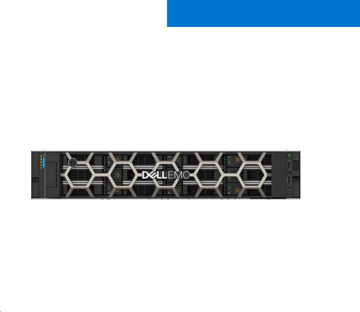
R540 Overview
Power your applications with a versatile 2-socket, 2U general-purpose rack server. Support various applications such as virtualization, video streaming, web tech, data analytics, and mail and messaging with the flexible Dell EMC PowerEdge R540. Its balanced combination of resources, expandability, and affordability adapt to the changing demands of a modern data center. Optimize your application performance with one-button tuning. Scale for future requirements with up to 14 x 3.5" drives. Embedded diagnostics and SupportAssist help to maximize uptime without added effort, in a worry-free environment.
Figure 1. Dell EMC PowerEdge R540
Topics:
•Introduction
•New technologies
Introduction
The PowerEdge R540 is a general-purpose platform with highly expandable memory - up to 512 GB with single processor and up to 1 TB with dual processors, and impressive I/O capabilities to match.

 NOTE: 768 GB max memory is recommended for performance optimized configurations. The R540 features:
●The 2nd Generation Intel® Xeon® Scalable processors product family (with up to 20 cores and two threads per core)
●Up to six channels with two DIMMs per channel per CPU and 16 DIMMs (supports DDR4 RDIMM)
●PCI Express (PCIe) 3.0 enabled expansion slots (with up to 48 lanes per CPU)
●M.2 based Boot Optimized Storage Solution module
●Modular storage and PCIe riser options
New technologies
The following are the new technologies that are featured on the PowerEdge R540:
Table 1. New technologies
New technology |
Detailed description |
|
|
|
|
The 2nd Generation Intel® Xeon® Scalable processor |
The 2nd Generation Intel® Xeon® Processor product family |
|
has advanced features such as, embedded PCIe lanes |
|
|
System Overview |
7 |
Table 1. New technologies (continued)
New technology |
Detailed description |
|
|
|
|
|
for improved I/O performance that delivers exceptional |
|
performance and value. |
|
For details, see the Processor section. |
|
|
Intel C620 series chipset |
The R540 system uses the Intel C620 chipset. It is a 2 chip |
|
platform - CPU and PCH. |
|
|
2666 MT/s DDR4 memory |
The Intel® Xeon® Scalable processor product family supports |
|
2666 MT/s memory and sixteen 288-pin DIMMs. |
|
The R540 system supports: |
|
● 6x DDR4 Channels per socket, 2 DIMMs per channel |
|
● Up to 2666 MT/s (configuration-dependent) |
|
● RDIMMs up to 32 GB, LRDIMMs 64 GB |
|
For details, see the Memory section. |
|
|
iDRAC9 with Lifecycle Controller |
The new embedded systems management solution for the |
|
Dell EMC systems features hardware and firmware inventory |
|
and alerting, data center level power monitoring, and faster |
|
performance. |
|
For details, see the Dell EMC OpenManage systems |
|
management section |
|
|
PERC S140 |
This new software RAID solution supports: |
|
● RAID 0, 1, 5, and Non-RAID |
|
● SATA hard drive and SSD devices only |
|
● Up to eight 3.5 inch and 2.5 inch hot-plug SATA HDDs or |
|
SSDs |
|
● Software RAID is through the Intel Lewisburg chipset |
|
● Software RAID solution is supported on Linux and |
|
Windows |
|
For details, see the Storage section. |
|
|
LCD bezel |
The PowerEdge R540 LCD control panel is embedded in an |
|
optional front bezel for easy access and management. |
|
|
Wireless Management |
The Quick Sync 2 BLE/WiFi module offers secure, wireless |
|
access to the embedded iDRAC, SupportAssist Collections, |
|
remote RACADM, and VNC remote console connectivity. |
|
|
8 System Overview

2
System features
Compared to previous generations, the PowerEdge R540 offers faster processing power and advanced system management. The PowerEdge R540 also provides extraordinary storage capacity options, making it well-suited for data-intensive applications that require greater storage, while not sacrificing the I/O performance.
Topics:
•Product comparison
•Technical specifications
Product comparison
Table 2. Feature comparison
Feature |
PowerEdge R540 |
PowerEdge R530 |
||
|
|
|
||
|
|
|
|
|
Processors |
The 2nd Generation Intel® Xeon® |
Intel® Xeon® Processor E5-2600 v3 or |
||
|
Scalable processor family |
E5-2600 v4 product family |
||
|
|
|
||
Chipset |
Intel C620 series chipset |
Intel C610 |
||
|
|
|
||
Memory |
16x DDR4 RDIMM/LRDIMM |
12 x DDR4 RDIMM/LRDIMM |
||
|
|
|
||
Drive bays |
12 x 3.5 inch SAS/SATA |
12 x 3.5 inch SAS/SATA |
||
|
Rear: 2 x 3.5 inch SAS/SATA |
|
|
|
|
|
|
||
PCIe Slots |
Up to 5 x PCIe Gen3 |
Up to 3 x PCIe Gen3, and 2 x PCIe Gen2 |
||
|
|
|
||
RAID Controller |
PERC 9/10 |
Mini-PERC 9 |
||
|
|
|
||
Backplane |
● 14 x 3.5 inches or 2.5 inch SATA/SAS |
● 8 x 2.5 inches or 3.5 inches SAS/ |
||
|
● 8 x 3.5 inch SATA/SAS |
|
SATA |
|
|
● 2 x 2.5 inches rear SATA/SAS |
|
|
|
Embedded NIC |
2x 1 Gb LOM and optional LAN on riser |
4 x 1 Gb |
||
|
card: |
|
|
|
|
● |
2X 1 GbE |
|
|
|
● |
2X 10 GbE |
|
|
|
● 2X 10 GbE SFP+ |
|
|
|
Power Supplies |
● 450 W AC Cable PSU |
● 450 W AC Cable PSU |
||
|
● |
495 W AC |
● |
495 W AC |
|
● |
750 W AC |
● |
750 W AC |
|
● 750 W Mixed Mode HVDC (For China |
● |
1100 W AC |
|
|
|
Only) |
● |
750 W DC |
|
● 750 W Mixed Mode (DC input for |
|
|
|
|
|
China Use Only) |
|
|
|
● |
1100 W AC |
|
|
|
● 1100 W Mixed Mode HVDC |
|
|
|
Remote Management |
iDRAC9 |
iDRAC8 |
||
|
|
|
||
TPM |
TPM 2.0 China, TPM1.2, TPM2.0 |
TPM China, TPM1.2, TPM2.0 |
||
|
|
|
||
Rear USB 3.0 port |
Two rear ports |
One rear port |
||
|
|
|
||
iDRAC Direct front port |
Micro-AB USB |
Micro-AB USB |
||
|
|
|
|
|
System features |
9 |
Table 2. Feature comparison (continued)
Feature |
PowerEdge R540 |
PowerEdge R530 |
|
|
|
|
|
|
Cooling Fan |
Up to 6 fan support |
Up to 6 fan support |
|
|
|
IDSDM Module |
Internal Dual SD Module (IDSDM) and |
Internal Dual SD Module (IDSDM) |
|
vFlash |
|
|
|
|
BOSS Module |
M.2 SATA interface |
None |
|
|
|
PERC |
PCIe PERC 9 or PERC 10 |
Mini-PERC 9 |
|
|
|
Technical specifications
Table 3. Technical specifications
Feature |
PowerEdge R540 technical specification |
|
|
|
|
|
|
|
Form factor |
2U rack |
|
|
|
|
Processor |
The 2nd Generation Intel® Xeon® Processor Scalable Family |
|
Processor sockets |
2 sockets |
|
|
|
|
Internal interconnect |
Up to 3 Intel Ultra Path Interconnect (Intel® UPI); up to 11.2 GT/s |
|
|
|
|
Chipset |
Intel C620 series Chipset |
|
|
|
|
Memory |
● |
Supports DDR4 RDIMM |
|
● Up to 512 GB RDIMM and 1 TB LRDIMMs |
|
|
● 16 DIMM slots: 8 GB, 16 GB, 32 GB, DDR4 up to 2666 MT/s |
|
I/O slots |
Up to 5 x PCIeGen 3 slots plus a dedicated PERC and LOM slot |
|
|
|
|
RAID controller |
Internal - PERC S140, PERC H330, PERC H330, PERC H730P, PERC H740P |
|
|
External HBA - PERC H840P and 12 Gb/s SAS HBA(non-RAID) |
|
|
|
|
Hard drives |
12 x 3.5 inch + 2 x 2.5-inch rear drive bays (supports 2.5-inch drive using 3.5-inch |
|
|
adapter) |
|
|
|
|
Embedded network adapter |
LOM1: 2x1G |
|
|
LOM Riser: 2x1GbE, 2X10GbE, 2x10GbE SFP+ |
|
|
|
|
Power supply |
Two hot plug PSUs or option for single cabled PSU |
|
|
● 495 W, 750 W, 1100 W hot plug PSU |
|
|
● Bronze efficiency 450 W cabled AC PSU |
|
|
|
|
Supported operating systems |
● |
Canonical® Ubuntu® LTS |
|
● |
Citrix® XenServer® |
|
● Microsoft Windows Server® with Hyper-V |
|
|
● Red Hat® Enterprise Linux |
|
|
● SUSE® Linux Enterprise Server |
|
|
● |
VMware® ESXi |
|
For more information, go to www.dell.com/ossupport |
|
|
|
|
Systems management |
Dell EMC Systems management consoles and tools: |
|
|
● |
OpenManage Enterprise |
|
● |
OpenManage Mobile |
|
● |
OpenManage Power Manager |
|
Embedded Management: |
|
|
|
|
10 System features
Table 3. Technical specifications (continued)
Feature |
PowerEdge R540 technical specification |
||
|
|
|
|
|
|
|
|
|
● |
|
iDRAC9 |
|
● |
|
iDRAC9 Direct |
|
● iDRAC REST API with Redfish |
||
|
● Quick Sync 2 BLE/wireless module |
||
|
Dell EMC OpenManage Integrations : |
||
|
● |
|
Microsoft® System Center |
|
● |
|
VMware® vCenter™ |
|
● |
|
BMC Truesight |
|
● Red Hat® Ansible® Modules |
||
|
Dell EMC OpenManage Connections: |
||
|
● Micro Focus Operations Manager I |
||
|
● Nagios Core and Nagios XI |
||
|
● |
|
IBM Tivoli® Netcool/OMNIbus |
|
|
|
|
Dimensions and weight |
● |
|
Height: 86.8 mm (3.41”) |
|
● Width*: 434 mm (17.08”) |
||
|
● Depth*: 703.76 mm (27.71”) |
||
|
● Weight: 29.68 kg (65.43 lb) |
||
|
|
|
NOTE: *Dimensions do not include bezel. |
|
|
|
|
|
|
||
|
|
||
|
|
|
|
|
|
||
Recommended support |
Dell ProSupport Plus for critical systems or Dell ProSupport for premium hardware |
||
|
and software support for your PowerEdge solution. Consulting and deployment |
||
|
offerings are also available. |
||
|
Contact your Dell representative for more information. Availability and terms of Dell |
||
|
Services vary by region. For more information, go to Dell.com/ServiceDescriptions. |
||
|
|
|
|
System features |
11 |
3
Chassis overview
The PowerEdge R540 is a dual socket, 2U rack server with up to 16 DIMMs, storage capacity of up to 12 drive slots, and the 2nd Generation Intel® Xeon® Scalable Family processors.
Table 4. R540 chassis options
Chassis Options |
Configurations |
|
|
|
|
Eight drive chassis |
Up to eight 3.5 or 2.5 inches in 3.5-inch adapter front accessible SAS/SATA drives. |
|
|
Twelve drive chassis |
Up to twelve 3.5 or 2.5 inches in front accessible SAS/SATA drives and two optional 3.5 inch |
|
rear accessible SAS/SATA drives. |
|
|
Topics:
•Front view of the system
•Back panel features
•Inside the system
•Security features
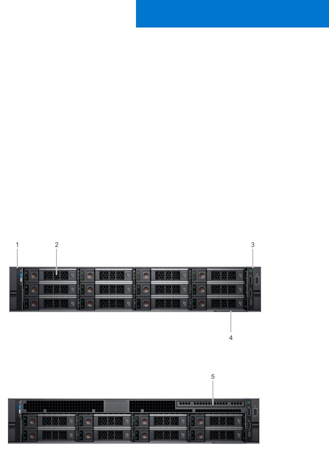
Front view of the system
The front view displays the features available on the front of the system.
Figure 2. Front view of 12 x 3.5 inch drive system
Figure 3. Front view of 8 x 3.5 inch drive system
12 Chassis overview
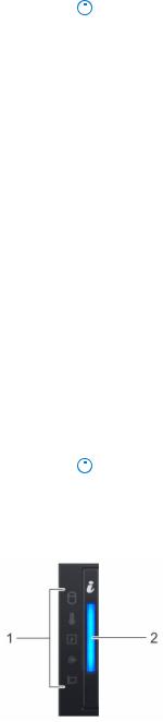
Table 5. Features available on the front of the system
Item |
Ports, panels, and |
Icon |
Description |
|||
|
slots |
|
|
|
|
|
|
|
|
|
|||
1 |
Left control panel |
N/A |
Contains the system health and system ID, status LED, and the |
|||
|
|
|
iDRAC Quick Sync 2 (wireless) indicator. |
|||
|
|
|
|
|
NOTE: The iDRAC Quick Sync 2 indicator is available only |
|
|
|
|
|
|
||
|
|
|
|
|||
|
|
|
|
|
on certain configurations. |
|
|
|
|
● Status LED: Enables you to identify any failed hardware |
|||
|
|
|
|
|
components. There are up to five status LEDs and an overall |
|
|
|
|
|
|
system health LED (Chassis health and system ID) bar. For |
|
|
|
|
|
|
more information, see the Status LED indicators section. |
|
|
|
|
● Quick Sync 2 (wireless): Indicates a Quick Sync enabled |
|||
|
|
|
|
|
system. The Quick Sync feature is optional. This feature |
|
|
|
|
|
|
allows management of the system by using mobile devices. |
|
|
|
|
|
|
This feature aggregates hardware or firmware inventory |
|
|
|
|
|
|
and various system level diagnostic and error information |
|
|
|
|
|
|
that can be used in troubleshooting the system. For |
|
|
|
|
|
|
more information, see the Integrated Dell Remote Access |
|
|
|
|
|
|
Controller User’s Guide at Dell.com/idracmanuals. |
|
2 |
Drive slots |
N/A |
Enable you to install drives that are supported on your |
|||
|
|
|
system. For more information about drives, see the Technical |
|||
|
|
|
specifications section. |
|||
3 |
Right control panel |
N/A |
Contains the power button, USB ports, iDRAC Direct (Micro-AB |
|||
|
|
|
USB), VGA port. |
|||
4 |
Information tag |
N/A |
|
|
|
|
The Information tag is a slide-out label panel that contains |
||||||
|
|
|
||||
|
|
|
system information such as Service Tag, NIC, MAC address, |
|||
|
|
|
and so on. If you have opted for the secure default access |
|||
|
|
|
to iDRAC, the Information tag also contains the iDRAC secure |
|||
|
|
|
default password. |
|||
5 |
Optical drive (optional) |
N/A |
One optional slim SATA DVD-ROM drive or DVD+/-RW drive. |
|||
|
|
|
|
|
NOTE: DVD devices are data only. |
|
|
|
|
|
|
||
|
|
|
|
|
||
|
|
|
|
|
|
|
|
|
|
|
|
|
|
Left control panel view
Figure 4. Left control panel without optional iDRAC Quick Sync 2.0 indicator
Chassis overview |
13 |
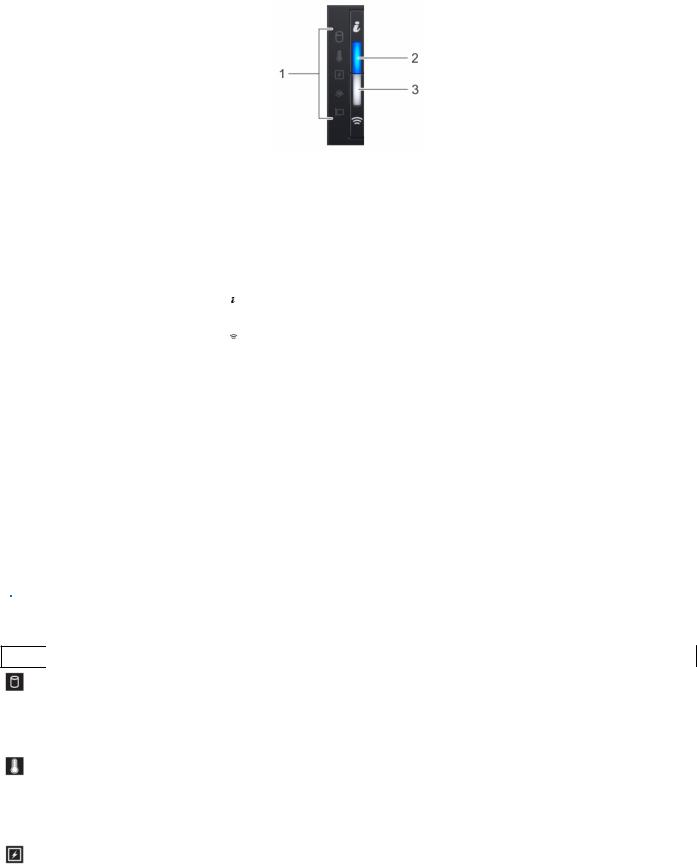
Figure 5. Left control panel with optional iDRAC Quick Sync 2.0 indicator
Table 6. Left control panel
Item |
Indicator, button, or |
Icon |
Description |
|
connector |
|
|
|
|
|
|
|
|
|
|
1 |
Status LED indicators |
N/A |
Indicate the status of the system. For more information, see the |
|
|
|
Status LED indicator section. |
|
System health and system |
|
Indicates the system health. |
2 |
|
||
|
ID indicator |
|
|
|
iDRAC Quick Sync |
|
|
3 |
|
Indicates if the iDRAC Quick Sync 2 wireless option is activated. |
|
|
2 wireless indicator |
|
The Quick Sync 2 feature allows management of the system |
|
(optional) |
|
using mobile devices. This feature aggregates hardware/ |
|
|
|
firmware inventory and various system level diagnostic/error |
|
|
|
information that can be used in troubleshooting the system. |
|
|
|
You can access system inventory, Dell Lifecycle Controller |
|
|
|
logs or system logs, system health status, and also configure |
|
|
|
iDRAC, BIOS, and networking parameters. You can also launch |
|
|
|
the virtual Keyboard, Video, and Mouse (KVM) viewer and |
|
|
|
virtual Kernel-based Virtual Machine (KVM), on a supported |
|
|
|
mobile device. For more information, see the Integrated Dell |
|
|
|
Remote Access Controller User's Guide at www.dell.com/ |
|
|
|
poweredgemanuals |
|
|
|
|
Status LED indicators

 NOTE: The indicators display solid amber if any error occurs.
Table 7. Status LED indicators and descriptions
Icon |
Description Condition |
Corrective action |
Drive |
The indicator turns solid amber if |
indicator |
there is a drive error. |
Temperature The indicator turns solid amber indicator if the system experiences a
thermal error (for example, the ambient temperature is out of range or there is a fan failure).
Electrical |
The indicator turns solid amber |
indicator |
if the system experiences an |
|
electrical error (for example, |
|
voltage out of range, or a failed |
|
power supply unit (PSU) or |
|
voltage regulator). |
●Check the System event log to determine if the drive has an error.
●Run the appropriate Online Diagnostics test. Restart the system and run embedded diagnostics (ePSA).
●If the drives are configured in a RAID array, restart the system, and enter the host adapter configuration utility.
Ensure that none of the following conditions exist:
●A cooling fan has been removed or has failed.
●System cover, air shroud, or back filler bracket is removed.
●Ambient temperature is too high.
●External airflow is obstructed.
Check the System event log or system messages for the specific issue. If it is due to a problem with the PSU, check the LED on the PSU. Reseat the PSU.
14 Chassis overview

Table 7. Status LED indicators and descriptions (continued)
Icon Description |
Condition |
Corrective action |
|
|
|
Memory |
The indicator turns solid amber if |
Check the System event log or system messages for the location of |
indicator |
a memory error occurs. |
the failed memory. Reseat the memory module. |
PCIe |
The indicator turns solid amber |
Restart the system. Update any required drivers for the PCIe card. |
indicator |
if a PCIe card experiences an |
Reinstall the card. |
|
error. |
|
|
|
|
iDRAC Quick Sync 2 indicator codes
iDRAC Quick Sync 2 module (optional) is located on the left control panel of your system.
Figure 6. iDRAC Quick Sync 2 indicators
Table 8. iDRAC Quick Sync 2 indicators and descriptions
iDRAC Quick Sync 2 indicator Condition code
Off (default state) |
Indicates that the iDRAC Quick Sync 2 |
|
feature is turned off. Press the iDRAC |
|
Quick Sync 2 button to turn on the |
|
iDRAC Quick Sync 2 feature. |
Solid white |
Indicates that iDRAC Quick Sync 2 is |
|
ready to communicate. Press the iDRAC |
|
Quick Sync 2 button to turn off. |
Blinks white rapidly |
Indicates data transfer activity. |
Blinks white slowly |
Indicates that firmware update is in |
|
progress. |
Blinks white five times rapidly |
Indicates that the iDRAC Quick Sync 2 |
and then turns off |
feature is disabled. |
Solid amber |
Indicates that the system is in fail-safe |
|
mode. |
Blinking amber |
Indicates that the iDRAC Quick Sync 2 |
|
hardware is not responding properly. |
Corrective action
If the LED fails to turn on, reseat the left control panel flex cable and check.
If the LED fails to turn off, restart the system.
NA
NA
Check if iDRAC Quick Sync 2 feature is configured to be disabled by iDRAC. For more information, see Integrated Dell Remote
Access Controller User's Guide at www.dell.com/ idracmanuals or Dell OpenManage Server Administrator User’s Guide atwww.dell.com/ openmanagemanuals .
Restart the system.
Restart the system.
Chassis overview |
15 |
Right control panel view
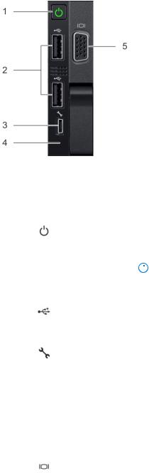
Figure 7. Right control panel
Table 9. Right control panel
Item |
Indicator, button, or connector |
Icon |
Description |
||
|
|
|
|
||
|
|
|
|
|
|
1 |
Power button |
|
Indicates if the system is powered on or off. |
||
|
|
|
Press the power button to manually power |
||
|
|
|
on or off the system. |
||
|
|
|
|
|
NOTE: Press the power button to |
|
|
|
|
|
|
|
|
|
|
||
|
|
|
|
|
gracefully shut down an ACPI-compliant |
|
|
|
|
|
operating system. |
|
USB port |
|
|
||
2 |
|
The USB ports are 4-pin, 2.0-compliant. |
|||
|
|
|
These ports enable you to connect USB |
||
|
|
|
devices to the system. |
||
|
iDRAC Direct (Micro-AB USB) |
|
The iDRAC Direct (Micro-AB USB) port |
||
3 |
|
||||
|
|
|
enables you to access the iDRAC Direct |
||
|
|
|
(Micro-AB) features. For more information, |
||
|
|
|
see the iDRAC User’s Guide at Dell.com/ |
||
|
|
|
idracmanuals. |
||
|
iDRAC Direct (Micro-AB USB) LED |
N/A |
The iDRAC Direct (Micro-AB USB) LED |
||
4 |
|||||
|
|
|
indicator lights up to indicate that the |
||
|
|
|
iDRAC Direct port is connected. For more |
||
|
|
|
information, see the iDRAC Direct LED |
||
|
|
|
indicator codes section. |
||
|
VGA port |
|
|
||
5 |
|
Enables you to connect a display device to |
|||
|
|
|
the system. For more information, see the |
||
|
|
|
Technical specifications section. |
||
|
|
|
|
|
|
iDRAC Direct LED indicator codes
The iDRAC Direct LED indicator lights up to indicate that the port is connected and is being used as a part of the iDRAC subsystem.
You can configure iDRAC Direct by using a USB to micro USB (type AB) cable, which you can connect to your laptop or tablet. The following table describes iDRAC Direct activity when the iDRAC Direct port is active:
16 Chassis overview

Table 10. iDRAC Direct LED indicator codes
iDRAC Direct LED indicator code
Solid green for two seconds
Flashing green (on for two seconds and off for two seconds)
Turns off
Condition
Indicates that the laptop or tablet is connected.
Indicates that the laptop or tablet connected is recognized.
Indicates that the laptop or tablet is unplugged.
Back panel features
Figure 8. Back panel features of 12 x 3.5 inch + 2 x 3.5 inch (rear) drive system
Figure 9. Back panel features of 12 x 3.5 inch + 2 x 3.5 inch (rear) drive system
Chassis overview |
17 |
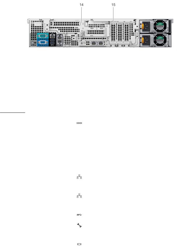
Figure 10. Back panel features of 12 x 3.5 inch drive system with butterfly riser
1. |
Serial port |
2. |
Drive (rear) |
3. |
Low profile riser right slot |
4. |
Low profile riser left slot |
5. |
Power supply unit (PSU) |
6. |
LOM riser ports |
7. |
Ethernet ports |
8. |
USB 3.0 ports |
9. |
iDRAC9 dedicated network port |
10. |
VGA port |
11. |
CMA power port |
12. |
System identification button |
13. |
Full height riser slot |
14. |
Butterfly riser slot |
15. PCIe slot
Table 11. Back panel features of R540
Item |
Features |
Icon |
|
Description |
|
|
|
|
|
1 |
Serial port |
|
|
Use the serial port to connect a serial device to the system. |
|
|
|
|
For more information about the supported serial port, see the |
|
|
|
|
Technical specifications section. |
2 |
|
|
|
|
Drive |
N/A |
|
Two optional rear drives supported for 12 x 3.5 inch system. |
|
3 |
Low profile riser right slot |
N/A |
|
Use the card slot to connect half-height PCIe expansion card |
|
|
|
|
on low profile riser. |
4 |
Low profile riser left slot |
N/A |
|
Use the card slot to connect half-height PCIe expansion card |
|
|
|
|
on low profile riser. |
5 |
Power supply unit (PSU) |
N/A |
|
For information about supported PSUs, see the Technical |
|
|
|
|
specifications section. |
6 |
LOM riser ports |
|
|
Use the Ethernet or SFP+ ports to connect Local Area |
|
|
|||
|
|
|
|
Networks (LANs) to the system. For more information about |
|
|
|
|
the supported Ethernet or SFP+ ports, see the Technical |
|
|
|
|
specifications section. |
7 |
Ethernet ports (2) |
|
|
Use the Ethernet ports to connect Local Area Networks |
|
|
|
|
(LANs) to the system. For more information about the |
|
|
|
|
supported Ethernet ports, see the Technical specifications |
|
|
|
|
section. |
8 |
USB 3.0 port |
|
|
Use the USB 3.0 port to connect USB devices to the system. |
|
|
|
|
These ports are 4-pin, USB 3.0-compliant. |
9 |
iDRAC9 dedicated network |
|
|
Use the iDRAC9 dedicated network port to securely access |
|
port |
|
|
the embedded iDRAC on a separate management network, see |
|
|
|
|
the Integrated Dell Remote Access Controller User’s Guide at |
|
|
|
|
Dell.com/idracmanuals. |
10 |
VGA port |
|
|
Use the VGA port to connect a display to the system. For |
|
|
|
|
more information about the supported VGA port, see the |
|
|
|
|
Technical specifications section. |
11 |
CMA power port |
N/A |
|
The Cable Management Arm (CMA) power port enables you |
|
||||
|
|
|
|
to connect to the CMA. |
|
|
|
|
|
18 Chassis overview

Table 11. Back panel features of R540 (continued)
Item |
Features |
Icon |
Description |
||
|
|
|
|
||
12 |
System identification button |
|
Press the system ID button: |
||
|
|
|
● To locate a particular system within a rack. |
||
|
|
|
● To turn the system ID on or off. |
||
|
|
|
To reset iDRAC, press and hold the button for more than 15 |
||
|
|
|
seconds. |
||
|
|
|
|
|
NOTE: |
|
|
|
|
||
|
|
|
|
|
● To reset iDRAC using system ID, ensure that the |
|
|
|
|
|
system ID button is enabled in the iDRAC setup. |
|
|
|
|
|
● If the system stops responding during POST, press and |
|
|
|
|
|
hold the system ID button (for more than five seconds) |
|
|
|
|
|
to enter the BIOS progress mode. |
13 |
Full height riser slot |
|
Use the card slots to connect full-height PCIe expansion cards |
||
|
|
|
on full height riser. |
||
14 |
Butterfly riser slot |
|
Use the card slots to connect full-height PCIe expansion cards |
||
|
|
|
on butterfly riser. |
||
15 |
PCIe slot |
|
Use the card slots to connect up to three half-height PCIe |
||
|
|
|
expansion cards on the system board. |
||
|
|
|
|
|
|
Inside the system

 NOTE: Components that are hot swappable are marked orange and touch points on the components are marked blue.
Chassis overview |
19 |
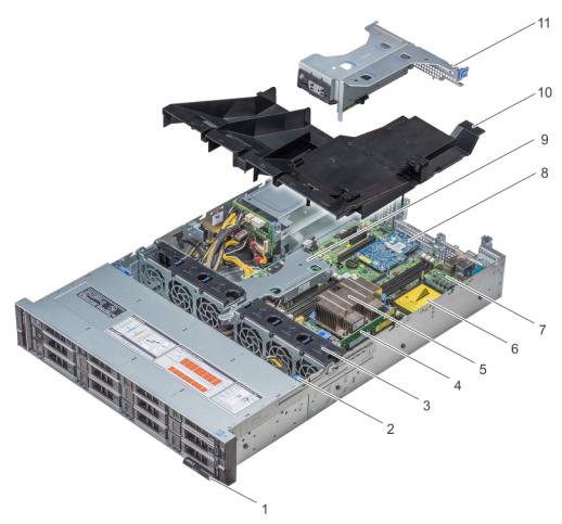
Figure 11. Inside the system without rear drive cage
20 Chassis overview
Loading...