


 Loading...
Reference Manual
EN

Contents |
|
Introduction |
3 |
Features .................................................................... |
3 |
Manuals for PX amplifier ........................................... |
3 |
Usage examples ....................................................... |
4 |
Use with two full-range speakers ......................... |
4 |
Use with a full-range speaker and subwoofer...... |
4 |
Use with a full-range speaker |
|
driven in bi-amp mode ...................................... |
5 |
Use for driving a subwoofer with a stereo signal |
...5 |
PX amplifier available system configurations....... |
6 |
Signal processing in PX amplifier ........................ |
7 |
Input sensitivity and amplifier gain ....................... |
7 |
Controls and functions |
8 |
Front panel ................................................................ |
8 |
Rear panel................................................................. |
9 |
Setup |
10 |
Setup procedure...................................................... |
10 |
Rack mounting ........................................................ |
11 |
Speaker connection ................................................ |
11 |
Connecting to the [SPEAKERS] terminal........... |
11 |
Panel Operation |
12 |
Basic operation ....................................................... |
12 |
Basic mode and Advanced mode ...................... |
12 |
Screen structure...................................................... |
13 |
Alert messages ....................................................... |
14 |
Panel lock................................................................ |
14 |
HOME screen.......................................................... |
15 |
CONFIG VIEW screen ........................................... |
16 |
MENU screen ......................................................... |
17 |
MENU screen types .......................................... |
17 |
Operation .......................................................... |
17 |
Operation tree ................................................... |
18 |
CONFIG WIZARD screen (Basic mode) ................ |
20 |
SP TYPE (speaker type) ................................... |
20 |
SP SERIES (speaker series) ............................ |
20 |
SP MODEL (speaker model)............................. |
20 |
HPF (high pass filter) ........................................ |
21 |
LPF (low pass filter) .......................................... |
21 |
X-OVER (crossover) ......................................... |
21 |
CONFIRMATION .............................................. |
21 |
CONFIG WIZARD screen (Advanced mode) ......... |
22 |
WIZARD MODE ................................................ |
22 |
SP TYPE (speaker type) ................................... |
22 |
ROUTING.......................................................... |
23 |
SENS./GAIN (input sensitivity/amplifier gain) ... |
24 |
SP SERIES (speaker series) ............................ |
24 |
SP MODEL (speaker model)............................. |
24 |
SP IMPEDANCE (speaker impedance) ............ |
24 |
CONFIRMATION .............................................. |
24 |
TUNING screen...................................................... |
25 |
D-CONTOUR .................................................... |
25 |
DELAY .............................................................. |
26 |
X-OVER (crossover) ......................................... |
26 |
HPF (high pass filter) ........................................ |
27 |
LPF (low pass filter) .......................................... |
27 |
POLARITY (speaker polarity)............................ |
28 |
SP DELAY......................................................... |
28 |
EQ (6 Band PEQ).............................................. |
29 |
LEVEL (output level) ......................................... |
29 |
LIMITER ............................................................ |
30 |
CHANNEL LINK ................................................ |
30 |
CHANNEL COPY .............................................. |
30 |
SAVE/LOAD ...................................................... |
31 |
AMP PRESET screen............................................. |
32 |
RECALL ............................................................ |
32 |
STORE .............................................................. |
32 |
CLEAR .............................................................. |
32 |
TITLE................................................................. |
33 |
PROTECT ......................................................... |
33 |
UTILITY screen ...................................................... |
34 |
PANEL SETUP.................................................. |
34 |
PANEL LOCK.................................................... |
34 |
HOME SCREEN (HOME screen)...................... |
35 |
IMPORT SP PRESET |
|
(import speaker preset) ................................. |
35 |
DEVICE BACKUP ............................................. |
36 |
DEVICE INFORMATION................................... |
36 |
INITIALIZE......................................................... |
36 |
LOG................................................................... |
37 |
Initializing the PX amplifier ..................................... |
37 |
Reference |
39 |
Function list ............................................................ |
39 |
Message list............................................................ |
42 |
Troubleshooting...................................................... |
44 |
General specifications ............................................ |
46 |
Block diagram......................................................... |
48 |
Dimensions............................................................. |
49 |
Current draw and thermal dissipation..................... |
50 |
Index....................................................................... |
54 |
PX10/PX8/PX5/PX3 Reference Manual 2

Introduction
Thank you for your purchase of the Yamaha PX10, PX8, PX5 or PX3 power amplifier. Please read through this manual carefully before using for the first time, in order to take full advantage of your PX power amplifier’s superlative features and enjoy trouble-free operation for years to come.
•Please read the Precautions in the PX10/PX8/PX5/PX3 Owner’s Manual before use.
•The illustrations as shown in this manual are for instructional purposes only.
•The company names and product names used in this manual are the trademarks or registered trademarks of their respective companies.
•In this manual, the PX10, PX8, PX5 and PX3 power amplifier models are referred to collectively as “PX amplifier.”
•Unless specified otherwise, the example illustrations used in this manual are taken from the PX10.
•The bitmap fonts used in this instrument have been provided by and are the property of Ricoh Co., Ltd.
Features
•Maximum output of 1,000W (PX10), from an exceptionally lightweight chassis.
•Yamaha’s proprietary Class-D and processing technologies provide superb sound quality and high reliability.
•Speaker presets that allow you to get the best possible performance from Yamaha speakers.
•A wide variety of DSP functions, including D-CONTOUR processing.
•Configuration Wizard that allows easy, optimal configuration for any speaker system.
•Broad range of input/output connectors.
Manuals for PX amplifier
•Owner’s Manual (included with the product)
Explains installation and basic operation.
•Reference Manual (this file)
Explains all required matters for setup and operation.
•Technical Specifications (included with the product)
Describes detailed specifications such as numerical values, dimensions, etc.
PX10/PX8/PX5/PX3 Reference Manual 3

Introduction — Usage examples
Usage examples
PX amplifiers can be used for various applications.
Use with two full-range speakers
This conventional application inputs stereo L/R signals to each channel (A/B) for stereo reproduction with two speakers.
Use with a full-range speaker and subwoofer
The input signal is divided into separate frequency ranges for driving a full-range speaker and subwoofer.
PX10/PX8/PX5/PX3 Reference Manual 4

Introduction — Usage examples
Use with a full-range speaker driven in bi-amp mode
The input signal is divided into separate frequency ranges for driving a two-way full-range speaker in bi-amp mode.
Channel A + Channel B
Use for driving a subwoofer with a stereo signal
Stereo input signals drive a subwoofer in Power Boost mode (PX5 and PX3 only)
(PX5)
PX10/PX8/PX5/PX3 Reference Manual 5

Introduction — Usage examples
PX amplifier available system configurations
PX amplifier can be used with the following 15 types of system configurations, including the examples above.
Output combination (speaker type)
Input configuration (routing)
Dual mode |
|
Parallel mode |
Single mode |
Sum mode |
||||||||
|
|
|
|
|
|
|
|
|
|
|
|
|
|
|
|
|
|
|
|
|
|
|
|
|
|
|
|
|
|
|
|
|
|
|
|
|
|
|
Channel A and channel B are |
After dividing channel A input |
After processing channel A input |
Mixes input signals from |
|||||||||
signal to channel A and channel B, |
signal, the signal is divided to A and |
|||||||||||
independent. |
channel A and channel B. |
|||||||||||
the signal is processed. |
|
channel B. |
||||||||||
|
|
|
|
|
|
|
||||||
|
|
|
|
|
|
|
|
|
|
|
|
|
Two full-range speakers
Two subwoofers
A full-range speaker and a subwoofer
A full-range speaker driven in bi-amp mode
Full-range speaker
Power Boost
mode
Subwoofer
NOTE
In Power Boost mode, the two-channel amplifiers are used as one-channel, high-power amplifier (PX5 and PX3 only).
PX10/PX8/PX5/PX3 Reference Manual 6
Introduction — Usage examples
Signal processing in PX amplifier
The PX amplifier gives you comprehensive control over the sound with input processors and speaker processors. The signals from the input connectors are processed in input processors equipped in each input connectors. The processed signals are added or divided depending on the set routing, processed finally with the speaker processor in each channel, and output from the [SPEAKERS] terminals.
Input processor Speaker processor
D-Contour |
|
Delay |
|
|
|
HPF |
|
LPF |
|
Polarity |
|
Speaker |
|
6 Band |
|
Level |
|
Limiter |
|
|
|
|
|
|
|
Delay |
|
PEQ |
|
|
|||||||
|
|
|
|
|
|
|
|
|
|
|
|
|
|
|
|
|
||
|
|
|
|
|
|
|
|
|
|
|
|
|
|
|
|
|
|
|
Refer to “TUNING screen” (page 25) in “Panel Operation” for details on the processing.
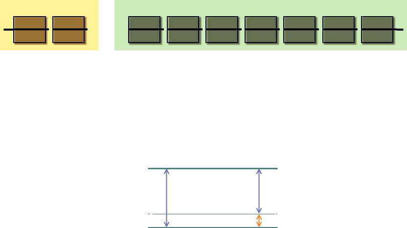
Input sensitivity and amplifier gain
The PX amplifier specifies the input sensitivity/amplifier gain from two input sensitivities or two amplifier gains. Input sensitivity controls the input signal level so that the amplifier can output the maximum power. If signals over the input sensitivity are input, the built-in limiter of the PX amplifier is activated. If the volume is lowered, the input sensitivity rises and the amplifier gain declines. Maximum power is constant if the volume is lowered.
For example, if the amplifier gain on the PX10 is set to 32 dB, the input sensitivity is +9.3 dBu and the maximum output power is 1,000 W (if speaker impedance is 8Ω). When the volume is not lowered (0 dB), output power of 1,000 W results with +9.3 dBu input.
When the volume on the PX10 is lowered to 6 dB, the input sensitivity is +15.3 dBu (9.3 dBu + 6 dBu) and the amplifier gain is 26 dB (32 dB - 6 dB). If a +15.3 dBu signal is input, maximum output power of 1,000 W is gained.
Maximum output power 41.3 dBu (1000 W, 8Ω)
Amplifier gain 26 dB
Amplifier gain 32 dB
Input sensitivity +15.3 dBu
Volume 6 dB
Input sensitivity +9.3 dBu
PX10/PX8/PX5/PX3 Reference Manual 7
Controls and functions
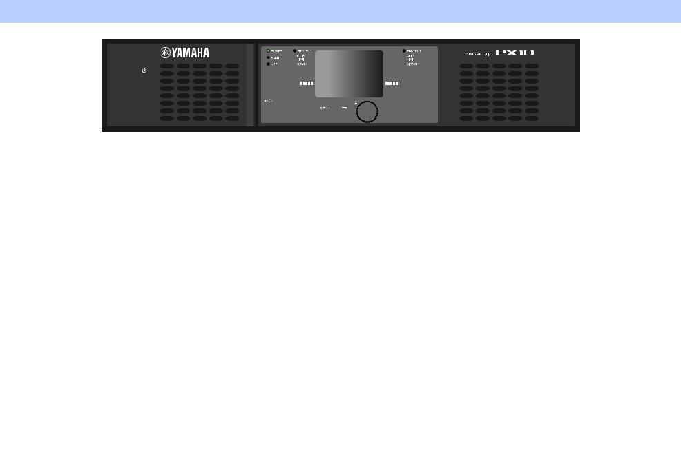
Front panel
q
qPower button
Turns the power to the unit on or off.
 WARNING
To ensure that high-volume noise is not output from the speakers, power-on the equipment starting with the audio sources, then the mixer and processors, and finally the amplifiers. Reverse this order when turning the system off.
w[POWER] indicator
Lights when the power is on.
e[ALERT] indicator
Lights when a problem in the device is detected, and continues to light until the cause of the problem is solved.
NOTE
Details of the problem are shown on the display (i).
Selecting the [  ] icon on the “HOME screen” (page 15) with the main knob calls up the operating log.
r[USB] indicator
Lights when a compatible USB flash drive is inserted into the [USB] terminal.
Flashes when the USB flash drive is being accessed.
NOTICE
Do not unplug the USB flash drive while the [USB] indicator is flashing. Doing so may cause data in the PX amplifier or USB flash drive to be corrupted or lost.
t[CLIP/LIMIT] indicator
Lights when the limiter is operating to protect the amplifier and the speaker, or when the input signal overflows in the digital circuit or clips at the amplifier output.
|
w |
u |
i |
u |
|
e |
t |
t |
|
|
|
|||
!5 |
r |
y |
|
y |
|
|
|
|
|
|
|
!2 |
|
!2 |
|
!3 |
!4 o !0 !1 |
!4 |
|
y[SIGNAL] indicator
Lights when the output is greater than -60 dB of maximum output level (8 ohms).
u[PROTECT] indicator
Lights when the protection circuit is operating.
iDisplay
Displays the status of the PX amplifier and setting menus. For details, refer to “Screen structure” (page 13).
o[MENU] key
Press this to move to the top MENU screen.
!0[  ] (Back) key
Press this to move up to the immediately higher menu level or previous display. Press and briefly hold the key to return the HOME screen.
!1Main knob
Rotate this to change the value of parameters and move the position of cursor. Press the knob to actually enter the set value or enable the selected item.
!2[A]/[B] key
Press this to change the values of parameters and move the cursor position.
NOTE
Press the main knob and [A] key to change the mute status of channel A. Press the main knob and [B] key to change the mute status of channel B.
!5
!3[USB] terminal
Insert a USB flash drive to read/load the data from/to the PX amplifier.
NOTICE
When the [USB] terminal is not used, attach the included USB cap to protect the terminal.
NOTE
The [USB] terminal is used in the following cases:
•Loading speaker preset: IMPORT SP PRESET (page 35)
•Writing operation log: LOG (page 37)
•Device backup: DEVICE BACKUP (page 36)
•Saving/loading SP TUNING DATA: SAVE/LOAD (page 31)
!4Volume knob
Adjusts the level from -∞ dB to 0 dB.
If “ROUTING” is set to something other than “DUAL,” adjust the output balance with the volume knob of channel B.
!5Intake ports
Air intakes for the cooling fan. Make sure to not block these ports.
NOTE
•The settings can be changed so that the display and indicators turn off automatically when panel is not operated (Black-out mode).
To activate the Black-out mode, select “ON” in UTILITY screen–PANEL SETUP screen–BLACKOUT screen (page 34). Keep in mind that the [POWER] indicator, [ALERT] indicator, [CLIP/ LIMIT] indicator, and [PROTECT] indicator all remain lit even if the device is in the Black-out mode.
•For the protection of the display, even if the Black-out mode is not active, the display automatically turns off if the PX amplifier has not been operated for 20 minutes. To turn on the display again, simply press any key on the front panel or rotate the main knob.
PX10/PX8/PX5/PX3 Reference Manual 8

Rear panel


 !9
!9


|
|
!7 |
|
|
|
||
|
|
||
!6 |
|||
|
|||
!6[INPUT] A/B connectors
Two types of input connectors are provided for both channels A and B. In Single mode or Parallel mode, the input connectors of channel A are used.
•XLR jack
XLR type 3-31 jack.
The polarity is shown below (IEC60268).
Hot |
Ground |
2 |
1 |
|
3 |
|
Cold |
•Phone jack
Balanced TRS phone jack.
The polarity of the connections is shown below.
Ring (cold)
|
|
|
|
|
|
|
|
|
|
|
|
|
|
|
|
|
|
|
|
|
|
|
|
|
|
|
|
Sleeve (ground) |
|
Tip (hot) |
||||
NOTE
The XLR input jack and the phones input jack of each channel are connected in parallel. The signal input from an XLR jack can be output from the phone jack and input to another amplifier. Only one of the jacks can be used as an input jack at one time; the signals from the jacks cannot be mixed.
!7[SPEAKERS] A/B terminals
Output terminals for speakers. Three types are available (below).
•Neutrik NL4MD speakON connector
•Binding post connector
•Phone jack
NOTICE
•Do not touch the terminals or metal parts of cords connected to the terminal. If connecting speakers to multiple connectors of the same channel results in a parallel connection, make sure that the total impedance of the speakers to be connected is not excessively low.
•The PX amplifier adopts BTL (Balanced Transformer Less) amplifier circuits. Connecting both terminals of channel A and channel B and contact between the terminal and the chassis may cause a failure or malfunction. Be careful not to connect or contact the two by mistake.
NOTE
In Power Boost mode, the output terminals of channel A are used (PX5/PX3 only).
Controls and functions — Rear panel
!8
!8[AC IN] connector
Connect the supplied AC power cord. First connect the AC power cord to the connector on the amplifier, and then plug it into an appropriate AC power outlet. Secure the AC power cord with the AC plug clamp to prevent accidental disconnection from the connector.
Installing the AC plug clamp
q |
w |
e |
!9Exhaust ports
Exhaust vents for the cooling fan. Make sure to not block these ports.
PX10/PX8/PX5/PX3 Reference Manual 9

Setup
Setup procedure
1. Set the PX amplifier in the desired location.
If the device is to be mounted in a rack, refer to “Rack mounting” (page 11).
2. Lower the two volume knobs to the minimum.
3. Connect speakers to the [SPEAKERS] terminals.
Refer to “Speaker connection” (page 11).
4. Connect outputs from sources, such as a mixer, to the [INPUT] connectors.
5. Connect the power cord to the [AC IN] connector.
AC IN connector
|
|
|
|
|
|
|
Power cord |
To AC power |
||||||||
|
|
|
|
|
|
|
||||||||||
|
|
|
|
|
|
|
outlet |
|||||||||
|
|
|
|
|
|
|
|
|
|
|
|
|||||
|
|
|
|
|
|
|
|
|
|
|
|
|
|
|
|
|
|
|
|
|
|
|
|
|
|
|
|
|
|
|
|
|
|
|
|
|
|
|
|
|
|
|
|
|
|
|
|
|
|
|
|
|
|
|
|
|
|
|
|
|
|
|
|
|
|
|
|
|
|
|
|
|
|
|
|
|
|
|
|
|
|
|
|
|
|
|
|
|
|
|
|
|
|
|
|
|
|
|
|
|
|
|
|
|
|
|
|
|
|
|
|
|
|
|
|
|
|
|
Secure the AC power cord with the AC plug clamp to prevent accidental disconnection from the connector.
Installing the AC plug clamp
q |
w |
e |
6. Turn on the device.
 WARNING
To ensure that high-volume noise is not output from the speakers, power-on the equipment starting with the audio sources, then the mixer and processors, and finally the amplifiers. Reverse this order when turning the system off.
7. Set up the system configuration with the Configuration Wizard.
Though the PX amplifier can be used as a normal amplifier by simply setting the volume knobs properly, using the Configuration Wizard to make settings enhances the performance of speakers.
Refer to “CONFIG WIZARD screen (Basic mode)” (page 20) or “CONFIG WIZARD screen (Advanced mode)” (page 22).
8. Rotate the volume knob to adjust the volume.
9. Control the tone in TUNING screen.
Refer to “TUNING screen” (page 25). In this condition, the device is available.
PX10/PX8/PX5/PX3 Reference Manual 10
Rack mounting
The PX amplifier can be mounted in an EIA standard rack (2U size).
Precautions for rack mounting
This device is rated for operation at ambient temperatures ranging from 0° to 40°C. When mounting the device with other device(s) in an EIA standard equipment rack, internal temperatures can exceed the specified upper limit, resulting in impaired performance or failure. When rack mounting the device, always observe the following requirements to avoid heat buildup:
•When mounting the unit in a rack with devices such as power amplifiers that generate a significant amount of heat, leave more than 1U of space between the device and other equipment. Also, either leave the open spaces uncovered or install appropriate ventilating panels to minimize the possibility of heat buildup. Multiple PX amplifiers can be mounted by stacking vertically.
•To ensure sufficient airflow, leave the rear of the rack open and position it at least 10 centimeters from walls or other surfaces. If the rear of the rack cannot be left open, install a commercially available fan or similar ventilating option to secure sufficient airflow. If you have installed a fan kit, there may be cases in which closing the rear of the rack will produce a greater cooling effect. Refer to the rack and/or fan unit manual for details.
Speaker connection
Connecting to the [SPEAKERS] terminal
 CAUTION
Make sure that the power is turned off, to avoid the danger of electrical shock.
Binding post connector
•Without plugs
Remove about 15 mm of insulation from the end of each speaker cable, pass the bare wire through the holes in the appropriate speaker terminals, and tighten the terminals to securely clamp the wires. Make sure that the bare wire ends do not jut out from the terminals and touch the chassis.
15 mm 

Setup — Rack mounting
•Y-plugs
From above, insert the Y-plugs all the way into the opening, and tighten the terminal.
0.25" (6.3 mm)
≤0.51" (12.9 mm)
speakON connector
Insert the speakON cable plug (Neutrik NL4) into the connector, and turn it to the right to lock it.
2–
2+
1+  1–
1– 
Channel A
Neutrik NL4 |
PX amplifier |
1+ |
A+ |
|
|
1– |
A– |
|
|
2+ |
B+ |
|
|
2– |
B– |
|
|
Channel B
Neutrik NL4 |
PX amplifier |
1+ |
B+ |
|
|
1– |
B– |
|
|
2+ |
(not connected) |
|
|
2– |
(not connected) |
|
|
PX10/PX8/PX5/PX3 Reference Manual 11
Panel Operation
Basic operation
Basic mode and Advanced mode
The PX amplifier provides two setting methods: Basic mode and Advanced mode.
Basic mode is convenient since it lets you use the device quickly and easily with minimum settings. Advanced mode is used when you want to set parameters in detail.
Each mode has a HOME screen and MENU screen.
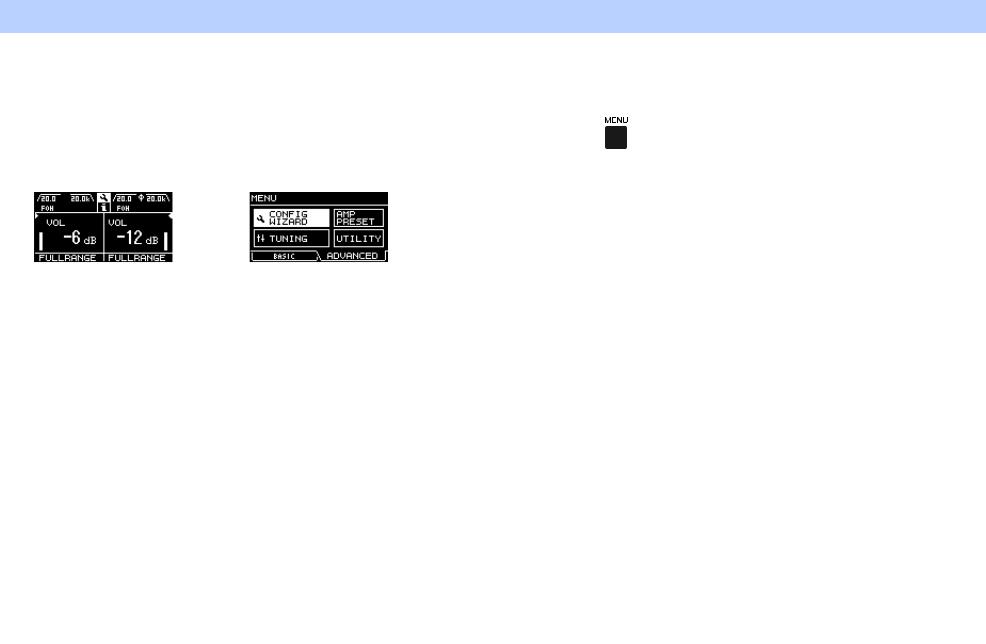
Example of screens
HOME screen (Basic mode) |
MENU screen (Advanced mode) |
To switch between Basic mode and Advanced mode
1. Press the [MENU] key to enter the MENU screen.
2. Rotate the main knob to select the tab of the desired mode, and then press the main knob.
• BASIC:
Basic mode
• ADVANCED:
Advanced mode
PX10/PX8/PX5/PX3 Reference Manual 12

Panel Operation — Screen structure
Screen structure
The screens of the PX amplifier differ depending on the selected mode, Basic or Advanced. The HOME screen and the CONFIG WIZARD screen in the MENU screen are in both modes, but displayed items differ. To switch between the modes, use the OPERATION MODE screen in the MENU screen.
|
|
|
|
|
|
ADVANCED |
||||||
|
|
|
|
|
|
|
|
|
|
|
|
BASIC |
Basic mode |
|
Advanced mode |
||||||||||
|
|
|
MENU screen |
|
|
|
|
MENU screen |
||||
|
|
|
|
|
|
|
||||||
HOME screen |
|
HOME screen |
||||||||||
|
|
|
|
|
MENU top screen |
|
|
|
|
|
|
MENU top screen |
|
|
|
|
|
|
|
|
|
|
|
|
|
|
|
|
|
|
|
|
|
|
|
|
|
|
CONFIG WIZARD screen |
CONFIG WIZARD screen |
CONFIG VIEW screen |
CONFIG VIEW screen |
TUNING screen |
TUNING screen |
AMP PRESET screen |
AMP PRESET screen |
UTILITY screen |
UTILITY screen |
PX10/PX8/PX5/PX3 Reference Manual 13
Alert messages
If an abnormality occurs in the PX amplifier, the [ALERT] indicator lights and an alert message appear on the display. Refer to the “Message list” (page 42) at the end of the book for details on each alert.
Panel Operation — Alert messages
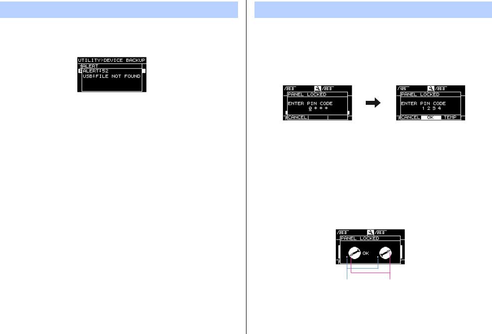
Panel lock
To prevent changes being made to the PX amplifier by mistake, use the panel lock function. This allows you to set a PIN code (a 4-digit identification number).
Refer to “UTILITY screen” – “PANEL LOCK” (page 34) for instructions.
To release the panel lock
If the panel controls are operated while the panel is locked, the following message appears in the display.
To release the panel lock, input the PIN code by rotating the main knob, select “OK,” and then press the main knob.
NOTE
•To release the panel lock temporarily, select “TEMP.” If “TEMP” is selected, the panel will be locked after turning off and turning on again.
•If a PIN code has been set, input the appropriate PIN code (set previously).
NOTE
If the volume knob is operated when the panel is locked with “ALL,” the following screen appears when the lock is released. Rotate the volume knob to match the actual value. The value of the volume cannot be changed unless the values match.
Actual value |
Value of the volume |
PX10/PX8/PX5/PX3 Reference Manual 14
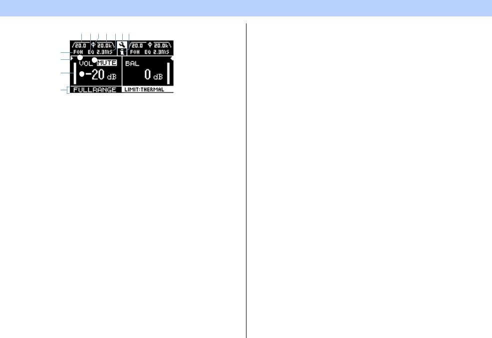
HOME screen
o !0i o u!1!2
y
t e q
r w
!3
qMute indication
Appears when the signal is muted.
w Volume indication
Shows the settings of the volume knobs.
In Power Boost mode, only channel A setting is shown.
e VOL/BAL/GAIN indication
Shows what appears at the volume indications (w).
•VOL: Input volume
•BAL: Output balance
•GAIN: Total level (gain from the input jack to the speaker output terminal)
NOTE
Displayed content depends on the input configuration (routing).
•In Dual mode: Input volume at both channels A and B.
•Other than Dual mode: Input volume at channel A, output balance at channel B. (In Power Boost mode, only channel A is shown.)
Set at “dB VALUE” (page 35) in UTILITY screen–HOME SCREEN screen, which is shown in VOL/ BAL/GAIN indication, input volume or total gain.
rLevel meter
Shows input or output level.
NOTE
Input and output can be switched from [HOME SCREEN] (page 35) in the UTILITY screen.
Panel Operation — HOME screen
tThreshold indication
Indicates the thresholds of the limiter on the output level of the speaker processors with “>” and “<” while the level meter shows the input level.
yD-CONTOUR indication
Shows the status of D-CONTOUR.
•OFF: Nothing appears.
•FOH/MAIN: “FOH” appears.
•MONITOR: “MONI” appears.
u Delay indication
Shows the delay time. When delay is off, nothing appears.
iPolarity indication
Appears when the polarity is inverted.
oFilter indication
Shows the cutoff frequency of the filter. When the filter is off, nothing appears.
!0EQ indication
Appears when the EQ is on.
!1CONFIG VIEW icon
CONFIG VIEW screen appears when selecting the icon by rotating the main knob and pressing it.
!2[  ] icon
Operation log appears when selecting the icon by rotating the main knob and pressing it. Refer to “Operation log indication” (page 37) for details on the operation log.
!3Speaker name, clipping/limiting message
Normally, this shows the name of the speaker that is connected, along with a related message if clipping or limiting has occurred.
NOTE
The displayed speaker name is the speaker preset recalled with the Configuration Wizard.
NOTE
Rotate the main knob to select the group of D-CONTOUR, delay, polarity and filter indications, and then press the main knob to call up the TUNING screen.
PX10/PX8/PX5/PX3 Reference Manual 15
Panel Operation — CONFIG VIEW screen
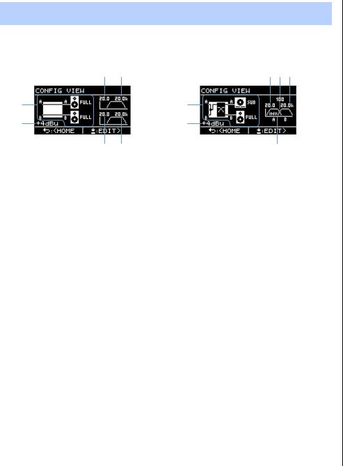
CONFIG VIEW screen
Called up by pressing the main knob when the HOME screen is shown.
The current settings are listed.
e r |
o!0!1 |
q |
u |
w |
i |
t y |
!2 |
q System configuration: page 6
w Input sensitivity/amplifier gain: page 24
e HPF cutoff frequency for channel A: pages 21, 27 r LPF cutoff frequency for channel A: pages 21, 27
tHPF cutoff frequency for channel B: pages 21, 27 y LPF cutoff frequency for channel B: pages 21, 27
u System configuration: page 6
i Input sensitivity/amplifier gain: page 24
o HPF cutoff frequency for channel A: pages 21, 27 !0Crossover frequency: pages 21, 26
!1LPF cutoff frequency for channel B: pages 21, 27 !2Polarity: page 28
To return to the HOME screen, press the [  ] (back) key.
To call up the CONFIG WIZARD screen, press the main knob when the CONFIG VIEW screen appears.
PX10/PX8/PX5/PX3 Reference Manual 16

MENU screen
Sets the basic condition of the device.
MENU screen types
The following MENU screens are available.
•CONFIG WIZARD screen (Basic mode) (Advanced mode)
•TUNING screen
•AMP PRESET screen
•UTILITY screen
NOTE
Refer to the “Function list” (page 39) for details on configurable items in each MENU screen.
Operation
To display the MENU screen:
Press the [MENU] key in the HOME screen.
Panel Operation — MENU screen
To move to the lower layer in MENU screens, or to select a parameter or other item:
Rotate the main knob to move to the desired item, and then press the main knob.
MENU top screen |
HPF screen |
TUNING screen |
Parameter edit screen |
To move to the upper layer in MENU screens:
Press the [  ] (back) key.
NOTE
The layer of the displayed screen is shown at the top of the screen.
To return to the HOME screen:
Press and hold the [  ] (back) key.
PX10/PX8/PX5/PX3 Reference Manual 17
Loading...