


 Loading...
Owner’s Manual
Keep This Manual For Future Reference.
EN

Contents |
|
PRECAUTIONS................................... |
5 |
Introduction .................................... |
8 |
Accessories......................................................... |
8 |
About utility software......................................... |
8 |
About firmware updates..................................... |
8 |
About the Owner’s Manual ................................ |
8 |
Conventions in this manual................................ |
8 |
An overview of the QL series ........... |
9 |
Features ............................................................. |
9 |
About the models ............................................ |
10 |
Controls and functions .................. |
11 |
Top panel ........................................................ |
11 |
Front panel ...................................................... |
15 |
Rear panel........................................................ |
16 |
Touch screen.................................. |
18 |
Basic touch screen operations .......................... |
18 |
On-screen user interface .................................. |
18 |
Viewing the touch screen................................. |
20 |
Using the tool buttons ..................................... |
21 |
Basic operation of the QL series .... |
22 |
Controlling selected channels |
|
(Selected Channel section)........................ |
22 |
Using the top panel (Channel Strip section) ..... |
22 |
Assigning a name............................................. |
23 |
Using libraries .................................................. |
24 |
Initializing settings ........................................... |
28 |
Copying and pasting settings........................... |
28 |
Comparing two sets of settings........................ |
29 |
Connection..................................... |
30 |
About network connections ............................. |
30 |
Connecting to I/O devices ............................... |
30 |
Audio input/output connections ...................... |
32 |
Installing an optional card................................ |
33 |
Quick Guide ................................... |
34 |
Connecting the devices.................................... |
34 |
Setting the input channels ............................... |
35 |
Sending an input channel signal to the |
|
STEREO bus............................................... |
36 |
Applying EQ/dynamics..................................... |
36 |
Setting the output channels ............................. |
37 |
Using GEQ ....................................................... |
37 |
Using Automixer .............................................. |
38 |
Applying effects ............................................... |
38 |
Changing the patch settings ............................ |
40 |
Grouping and linking....................................... |
41 |
Using talkback.................................................. |
41 |
Routing the oscillator to an output |
|
channel..................................................... |
42 |
Using scene memories ..................................... |
42 |
Recording and playing audio using a USB |
|
flash drive ................................................. |
43 |
Saving and loading the unit settings ................ |
44 |
Other functions ............................. |
45 |
Adjusting the brightness of the touch |
|
screen, lamps, and other indicators ........... |
45 |
Setting the date and time of the internal |
|
clock ......................................................... |
45 |
Initializing the unit to factory default settings... |
46 |
Adjusting the faders |
|
(Calibration function)................................ |
46 |
Troubleshooting ............................ |
48 |
Attaching the RK1 rackmount kit |
|
(sold separately)............................ |
50 |
General specifications ................... |
51 |
Dimensional Diagrams................... |
52 |
Index .............................................. |
53 |
Block Diagram ............ |
End of Manual |
Level Diagram............. |
End of Manual |
2 |
|
Owner’s Manual |
|
|
|
The above warning is located on the rear/side of the unit.
L’avertissement ci-dessus est situé sur le arrière/côté de l’appareil.
Explanation of Graphical Symbols Explication des symboles
The lightning flash with arrowhead symbol within an equilateral triangle is intended to alert the user to the presence of uninsulated “dangerous voltage” within the product’s enclosure that may be of sufficient magnitude to constitute a risk of electric shock to persons. L’éclair avec une flèche à l’intérieur d’un triangle équilatéral est destiné à attirer l’attention de l’utilisateur sur la présence d’une « tension dangereuse » non isolée à l’intérieur de l’appareil, pouvant être suffisamment élevée pour constituer un risque d’électrocution.
The exclamation point within an equilateral triangle is intended to alert the user to the presence of important operating and maintenance (servicing) instructions in the literature accompanying the product.
Le point d’exclamation à l’intérieur d’un triangle équilatéral est destiné à attirer l’attention de l’utilisateur sur la présence d’instructions importantes sur l’emploi ou la maintenance (réparation) de l’appareil dans la documentation fournie.
IMPORTANT SAFETY INSTRUCTIONS
1Read these instructions.
2Keep these instructions.
3Heed all warnings.
4Follow all instructions.
5Do not use this apparatus near water.
6Clean only with dry cloth.
7Do not block any ventilation openings. Install in accordance with the manufacturer’s instructions.
8Do not install near any heat sources such as radiators, heat registers, stoves, or other apparatus (including amplifiers) that produce heat.
9Do not defeat the safety purpose of the polarized or grounding-type plug. A polarized plug has two blades with one wider than the other. A grounding type plug has two blades and a third grounding prong. The wide blade or the third prong are provided for your safety. If the provided plug does not fit into your outlet, consult an electrician for replacement of the obsolete outlet.
10Protect the power cord from being walked on or pinched particularly at plugs, convenience receptacles, and the point where they exit from the apparatus.
11Only use attachments/accessories specified by the manufacturer.
12Use only with the cart, stand, tripod, bracket,
or table specified by the manufacturer, or sold with the apparatus. When a cart is used, use caution when moving the cart/apparatus combination to avoid injury from tip-over.
13Unplug this apparatus during lightning storms or when unused for long periods of
time.
14Refer all servicing to qualified service per-
sonnel. Servicing is required when the apparatus has been damaged in any way, such as power-supply cord or plug is damaged, liquid has been spilled or objects have fallen into the apparatus, the apparatus has been exposed to rain or moisture, does not operate normally, or has been dropped.
WARNING
TO REDUCE THE RISK OF FIRE OR ELECTRIC SHOCK, DO NOT EXPOSE THIS APPARATUS TO RAIN OR MOISTURE.
(UL60065_03)
PRÉCAUTIONS CONCERNANT LA SÉCURITÉ
1Lire ces instructions.
2Conserver ces instructions.
3Tenir compte de tous les avertissements.
4Suivre toutes les instructions.
5Ne pas utiliser ce produit à proximité d’eau.
6Nettoyer uniquement avec un chiffon propre et sec.
7Ne pas bloquer les orifices de ventilation. Installer l’appareil conformément aux instructions du fabricant.
8Ne pas installer l’appareil à proximité d’une source de chaleur comme un radiateur, une bouche de chaleur, un poêle ou tout autre appareil (y compris un amplificateur) produisant de la chaleur.
9Ne pas modifier le système de sécurité de la fiche polarisée ou de la fiche de terre. Une fiche polarisée dispose de deux broches dont une est plus large que l’autre. Une fiche de terre dispose de deux broches et d’une troisième pour le raccordement à la terre. Cette broche plus large ou cette troisième broche est destinée à assurer la sécurité de l’utilisateur. Si la fiche équipant l’appareil n’est pas compatible avec les prises de courant disponibles, faire remplacer les prises par un électricien.
10Acheminer les cordons d’alimentation de sorte qu’ils ne soient pas piétinés ni coincés, en faisant tout spécialement attention aux fiches, prises de courant et au point de sortie de l’appareil.
11Utiliser exclusivement les fixations et accessoires spécifiés par le fabricant.
12Utiliser exclusivement le chariot, le stand, le trépied, le support ou la table recommandés
par le fabricant ou vendus avec cet appareil. Si l’appareil est posé sur un chariot, déplacer le chariot avec précaution pour éviter tout risque de chute et de blessure.
13 Débrancher l’appareil en cas d’orage ou lorsqu’il doit rester hors service pendant une période prolongée.
14Confier toute réparation à un personnel qualifié. Faire réparer l’appareil s’il a subi tout dommage, par exemple si la fiche ou le cordon d’alimentation est endommagé, si du liquide a coulé ou des objets sont tombés à l’intérieur de l’appareil, si l’appareil a été exposé à la pluie ou à de l’humidité, si l’appareil ne fonctionne pas normalement ou est tombé.
AVERTISSEMENT
POUR RÉDUIRE LES RISQUES D’INCENDIE OU DE DÉCHARGE ÉLECTRIQUE, N’EXPOSEZ PAS CET APPAREIL À LA PLUIE OU À L’HUMIDITÉ.
(UL60065_03)
Owner’s Manual |
|
3 |
|
|
|
|
FCC INFORMATION (U.S.A.) |
||
1. |
IMPORTANT NOTICE: DO NOT MODIFY THIS UNIT! |
not guarantee that interference will not occur in all installations. If |
|
|
This product, when installed as indicated in the instructions con- |
this product is found to be the source of interference, which can be |
|
|
tained in this manual, meets FCC requirements. Modifications not |
determined by turning the unit “OFF” and “ON”, please try to elimi- |
|
|
expressly approved by Yamaha may void your authority, granted by |
nate the problem by using one of the following measures: |
|
|
the FCC, to use the product. |
Relocate either this product or the device that is being affected by |
|
2. IMPORTANT: When connecting this product to accessories and/ |
|||
the interference. |
|||
|
or another product use only high quality shielded cables. Cable/s |
||
|
Utilize power outlets that are on different branch (circuit breaker or |
||
|
supplied with this product MUST be used. Follow all installation |
||
|
fuse) circuits or install AC line filter/s. |
||
|
instructions. Failure to follow instructions could void your FCC |
||
|
In the case of radio or TV interference, relocate/reorient the |
||
|
authorization to use this product in the USA. |
||
3. NOTE: This product has been tested and found to comply with the |
antenna. If the antenna lead-in is 300 ohm ribbon lead, change the |
||
|
requirements listed in FCC Regulations, Part 15 for Class “B” digital |
lead-in to co-axial type cable. |
|
|
If these corrective measures do not produce satisfactory results, |
||
|
devices. Compliance with these requirements provides a reason- |
||
|
able level of assurance that your use of this product in a residential |
please contact the local retailer authorized to distribute this type of |
|
|
environment will not result in harmful interference with other elec- |
product. If you can not locate the appropriate retailer, please contact |
|
|
tronic devices. This equipment generates/uses radio frequencies |
Yamaha Corporation of America, Electronic Service Division, 6600 |
|
|
and, if not installed and used according to the instructions found in |
Orangethorpe Ave, Buena Park, CA90620 |
|
|
the users manual, may cause interference harmful to the operation |
The above statements apply ONLY to those products distributed by |
|
|
of other electronic devices. Compliance with FCC regulations does |
Yamaha Corporation of America or its subsidiaries. |
|
|
|
||
* This applies only to products distributed by YAMAHA CORPORATION OF AMERICA. |
(class B) |
||
ADVARSEL!
Lithiumbatteri—Eksplosionsfare ved fejlagtig håndtering. Udskiftning må kun ske med batteri af samme fabrikat og type. Levér det brugte batteri tilbage til leverandoren.
VARNING
Explosionsfara vid felaktigt batteribyte. Använd samma batterityp eller en ekvivalent typ som rekommenderas av apparattillverkaren. Kassera använt batteri enligt fabrikantens instruktion.
VAROITUS
Paristo voi räjähtää, jos se on virheellisesti asennettu. Vaihda paristo ainoastaan laitevalmistajan suosittelemaan tyyppiin. Hävitä käytetty paristo valmistajan ohjeiden mukaisesti.
(lithium caution)
NEDERLAND / THE NETHERLANDS
•Dit apparaat bevat een lithium batterij voor geheugen back-up.
•This apparatus contains a lithium battery for memory back-up.
•Raadpleeg uw leverancier over de verwijdering van de batterij op het moment dat u het apparaat ann het einde van de levensduur of gelieve dan contact op te nemen met de vertegenwoordiging van Yamaha in uw land.
•For the removal of the battery at the moment of the disposal at the end of life please consult your retailer or Yamaha representative office in your country.
•Gooi de batterij niet weg, maar lever hem in als KCA.
•Do not throw away the battery. Instead, hand it in as small chemical waste.
(lithium disposal)
This product contains a battery that contains perchlorate material.
Perchlorate Material—special handling may apply,
See www.dtsc.ca.gov/hazardouswaste/perchlorate.
* This applies only to products distributed by |
(Perchlorate) |
YAMAHA CORPORATION OF AMERICA. |
|
COMPLIANCE INFORMATION STATEMENT (DECLARATION OF CONFORMITY PROCEDURE)
Responsible Party: Yamaha Corporation of America
Address: 6600 Orangethorpe Ave., Buena Park, Calif.
90620
Telephone: 714-522-9011
Type of Equipment: Digital Mixing Console
Model Name: QL5/QL1
This device complies with Part 15 of the FCC Rules.
Operation is subject to the following two conditions:
1)this device may not cause harmful interference, and
2)this device must accept any interference received including interference that may cause undesired operation.
See user manual instructions if interference to radio reception is suspected.
* This applies only to products distributed by |
(FCC DoC) |
YAMAHA CORPORATION OF AMERICA. |
|
IMPORTANT NOTICE FOR THE UNITED KINGDOM
Connecting the Plug and Cord
WARNING: THIS APPARATUS MUST BE EARTHED
IMPORTANT. The wires in this mains lead are coloured in accordance with the following code:
GREEN-AND-YELLOW : EARTH
BLUE |
: NEUTRAL |
BROWN |
: LIVE |
As the colours of the wires in the mains lead of this apparatus may not correspond with the coloured markings identifying the terminals in your plug proceed as follows:
The wire which is coloured GREEN-and-YELLOW must be connected to the terminal in the plug which is marked by the letter E or by the safety earth symbol  or colored GREEN or GREEN-and-YELLOW. The wire which is coloured BLUE must be connected to the terminal which is marked with the letter N or coloured BLACK.
The wire which is coloured BROWN must be connected to the terminal which is marked with the letter L or coloured RED.
(3 wires)
(class b korea)
4 |
|
Owner’s Manual |
|
|
|

PRECAUTIONS
PLEASE READ CAREFULLY BEFORE PROCEEDING
Please keep this manual in a safe place for future reference.
 WARNING
Always follow the basic precautions listed below to avoid the possibility of serious injury or even death from electrical shock, short-circuiting, damages, fire or other hazards. These precautions include, but are not limited to, the following:
Power supply/power cord
•Do not place the power cord near heat sources such as heaters or radiators, and do not excessively bend or otherwise damage the cord, place heavy objects on it, or place it in a position where anyone could walk on, trip over, or roll anything over it.
•Only use the voltage specified as correct for the device. The required voltage is printed on the name plate of the device.
•Use only the supplied power cord/plug.
If you intend to use the device in an area other than in the one you purchased, the included power cord may not be compatible. Please check with your Yamaha dealer.
•Check the electric plug periodically and remove any dirt or dust which may have accumulated on it.
•Be sure to connect to an appropriate outlet with a protective grounding connection. Improper grounding can result in electrical shock, damage to the device(s), or even fire.
Do not open
•This device contains no user-serviceable parts. Do not open the device or attempt to disassemble the internal parts or modify them in any way. If it should appear to be malfunctioning, discontinue use immediately and have it inspected by qualified Yamaha service personnel.
Water warning
•Do not expose the device to rain, use it near water or in damp or wet conditions, or place on it any containers (such as vases, bottles or glasses) containing liquids which might spill into any openings. If any liquid such as water seeps into the device, turn off the power immediately and unplug the power cord from the AC outlet. Then have the device inspected by qualified Yamaha service personnel.
•Never insert or remove an electric plug with wet hands.
Fire warning
•Do not put burning items, such as candles, on the unit. A burning item may fall over and cause a fire.
PA_en_2 1/2
If you notice any abnormality
•When one of the following problems occur, immediately turn off the power switch and disconnect the electric plug from the outlet. Then have the device inspected by Yamaha service personnel.
-The power cord or plug becomes frayed or damaged.
-It emits unusual smells or smoke.
-Some object has been dropped into the device.
-There is a sudden loss of sound during use of the device.
•If this device should be dropped or damaged, immediately turn off the power switch, disconnect the electric plug from the outlet, and have the device inspected by qualified Yamaha service personnel.
 CAUTION
Always follow the basic precautions listed below to avoid the possibility of physical injury to you or others, or damage to the device or other property. These precautions include, but are not limited to, the following:
Power supply/power cord
•When removing the electric plug from the device or an outlet, always hold the plug itself and not the cord. Pulling by the cord can damage it.
•Remove the electric plug from the outlet when the device is not to be used for extended periods of time, or during electrical storms.
Location
•Do not place the device in an unstable position where it might accidentally fall over.
•Do not block the vents. This device has ventilation holes at the rear/sides to prevent the internal temperature from becoming too high. In particular, do not place the device on its side or upside down. Inadequate ventilation can result in overheating, possibly causing damage to the device(s), or even fire.
•Keep device away from the reach of children.
•Do not place the device in a location where it may come into contact with corrosive gases or salt air. Doing so may result in malfunction.
•Avoid being near the device during a disaster, such as an earthquake. Since the device may turn over or fall and cause injury, stay away from the device quickly and move to a safe place.
•Before moving the device, remove all connected cables.
•When setting up the device, make sure that the AC outlet you are using is easily accessible. If some trouble or malfunction occurs, immediately turn off the power switch and disconnect the plug from the outlet. Even when the power switch is turned off, electricity is still flowing to the product at the minimum level. When you are not using the product for a long time, make sure to unplug the power cord from the wall AC outlet.
•When setting up the device, make sure that the power switch can be easily turned ON/OFF. If some trouble or malfunction occurs, immediately turn off the power switch and disconnect the plug from the AC outlet.
•When transporting or moving the device, always use two or more people. Attempting to lift the device by yourself may damage your back, result in other injury, or cause damage to the device itself.
Owner’s Manual |
|
5 |
|
|
|

PA_en_2 2/2
Connections
•Before connecting the device to other devices, turn off the power for all devices. Before turning the power on or off for all devices, set all volume levels to minimum.
Maintenance
•Remove the power plug from the AC outlet when cleaning the device.
Handling caution
•Do not insert your fingers or hands in any gaps or openings on the device (vents).
•Avoid inserting or dropping foreign objects (paper, plastic, metal, etc.) into any gaps or openings on the device (vents) If this happens, turn off the power immediately and unplug the power cord from the AC outlet. Then have the device inspected by qualified Yamaha service personnel.
•Do not rest your weight on the device or place heavy objects on it, and avoid use excessive force on the buttons, switches or connectors.
•Do not use headphones for a long period of time at a high or uncomfortable volume level, since this can cause permanent hearing loss. If you experience any hearing loss or ringing in the ears, consult a physician.
Backup battery
•Do not replace the backup battery by yourself. Doing so may cause an explosion and/or damage to the device(s).
If the backup battery power is fully depleted, have qualified Yamaha service personnel replace the battery.
Yamaha cannot be held responsible for damage caused by improper use or modifications to the device, or data that is lost or destroyed.
6 |
|
Owner’s Manual |
|
|
|
NOTICE
To avoid the possibility of malfunction/damage to the product, damage to data, or damage to other property, follow the notices below.
Handling and Maintenance
•Do not use the device in the vicinity of a TV, radio, stereo equipment, mobile phone, or other electric devices. Otherwise, the device, TV, or radio may generate noise.
•Do not expose the device to excessive dust or vibration, or extreme cold or heat (such as in direct sunlight, near a heater, or in a car during the day), in order to prevent the possibility of panel disfiguration, unstable operation, or damage to the internal components.
•Do not place vinyl, plastic or rubber objects on the device, since this might discolor the panel.
•When cleaning the device, use a dry and soft cloth. Do not use paint thinners, solvents, cleaning fluids, or chemicalimpregnated wiping cloths.
•Condensation can occur in the device due to rapid, drastic changes in ambient temperature—when the device is moved from one location to another, or air conditioning is turned on or off, for example. Using the device while condensation is present can cause damage. If there is reason to believe that condensation might have occurred, leave the device for several hours without turning on the power until the condensation has completely dried out.
•Avoid setting all equalizer controls and faders to their maximum. Depending on the condition of the connected devices, doing so may cause feedback and may damage the speakers.
•Do not apply oil, grease, or contact cleaner to the faders. Doing so may cause problems with electrical contact or fader motion.
•When turning on the AC power in your audio system, always turn on the power amplifier/the device LAST, to avoid speaker damage. When turning the power off, the power amplifier/the device should be turned off FIRST for the same reason.
•The rubber feet included in this package can be attached to the speaker to prevent slippage when it is to be used on a slippery surface.
•Always turn the power off when the device is not in use.
Saving data
•This device has a built-in backup battery that maintains internal clock data even when the device’s power is switched off. However, the backup battery will eventually become depleted, and when that happens the internal clock data will be reset. Replace the backup battery before it becomes fully depleted. When the backup battery is running low, the LCD display indicates “Low Battery” when you start up the system.
In this case, contact your Yamaha dealer and have qualified Yamaha service personnel replace the backup battery.
The average life of the backup battery is approximately five years, depending on operating conditions.
Connectors
•XLR-type connectors are wired as follows (IEC60268 standard): pin 1: ground, pin 2: hot (+), and pin 3: cold (–).
Information
About copyrights
•Copying of the commercially available musical data including but not limited to MIDI data and/or audio data is strictly prohibited except for your personal use.
About this manual
•The illustrations and LCD screens as shown in this manual are for instructional purposes only, and may appear somewhat different from those on your device.
•Windows is a registered trademark of Microsoft® Corporation in the United States and other countries.
•Apple, Mac, Macintosh and iPad are trademarks of Apple Inc., registered in the U.S. and other countries.
•The bitmap fonts used in this instrument have been provided by and are the property of Ricoh Co., Ltd.
•MPEG Layer-3 audio coding technology licensed from
Fraunhofer IIS and Thomson.
•The company names and product names in this manual are the trademarks or registered trademarks of their respective companies.
Information for Users on Collection and Disposal of Old Equipment
This symbol on the products, packaging, and/or accompanying documents means that used electrical and electronic products should not be mixed with general household waste.
For proper treatment, recovery and recycling of old products, please take them to applicable collection points, in accordance with your national legislation and the Directives 2002/96/EC.
By disposing of these products correctly, you will help to save valuable resources and prevent any potential negative effects on human health and the environment which could otherwise arise from inappropriate waste handling.
For more information about collection and recycling of old products, please contact your local municipality, your waste disposal service or the point of sale where you purchased the items.
[For business users in the European Union]
If you wish to discard electrical and electronic equipment, please contact your dealer or supplier for further information.
[Information on Disposal in other Countries outside the European Union]
This symbol is only valid in the European Union. If you wish to discard these items, please contact your local authorities or dealer and ask for the correct method of disposal.
(weee_eu_en_01)
Owner’s Manual |
|
7 |
|
|
|

Introduction
Introduction
Thank you for choosing a Yamaha QL series QL5/QL1 Digital Mixing Console. To take full advantage of the superior features and performance offered by your QL series console, and to enjoy years of trouble-free use, please read this owner’s manual carefully before operating your console. After you have read the manual, keep it in a safe place.
Accessories
•AC power cord
•Owner’s Manual (this document)
•Dante Virtual Soundcard license code
•Dust cover (QL5 only)
About utility software
QL series products can be used with a variety of utility software. Information about downloading, installing and setting up the software applications is available on the Yamaha Pro Audio website. In addition, refer to the installation guide that comes with each downloaded application.
http://www.yamahaproaudio.com/
• QL Editor
This software application enables you to set up and operate the unit from a connected computer. You can also use the application to back up console settings or set console parameters without connecting the unit.
• Console File Converter
This software application enables you to convert between Yamaha PM5D, M7CL, LS9, CL and QL series setting files.
• QL StageMix
This software application enables you to control the unit remotely from an iPad on a WiFi network.
NOTE
iOS applications may not be supported in your area. Please check with your Yamaha dealer.
About firmware updates
This product enables you to update the unit firmware to improve the operation, add functions, and correct possible malfunctions. The following two types of firmware are available for the unit.
•Console firmware
•Dante module firmware
You must update each type of firmware separately. Details on updating the firmware are available on the following website. For information about updating and setting up the unit, please refer to the firmware update guide available on the website.
http://www.yamahaproaudio.com/
About the Owner’s Manual
Owner’s Manual (this document)
This book primarily explains panel controls and functions and basic operation of the QL series.
In this manual, most explanations refer to the QL5.
Reference Manual (PDF format; downloadable from the website)
This book primarily explains details about functions, effects parameters, and MIDI.
The Reference Manual is an electronic file in PDF format. Use PDF viewing software such as Adobe® Reader® to read this manual. You can download the latest Adobe Reader application from the website listed below.
http://www.adobe.com/
Help file (XML file; downloadable from the website)
You can read this Help file on the unit’s screen. Load the file on the unit, then press the Help button on the display to view related sections.
You can download the Reference Manual and Help file from the following website.
http://www.yamahaproaudio.com/
Conventions in this manual
In this manual, switch-type controllers on the panel are called “keys.” Control knobs on the panel are called “knobs.” Some knobs rotate from a minimum value to a maximum value, while others rotate endlessly.
Virtual buttons displayed on the screen are called “buttons,” and virtual knobs are called “knobs.” Controls located on the panel are enclosed in square brackets [ ] (e.g., [CUE] key) to distinguish them from virtual buttons and knobs displayed on screen. For some controls, the name of the section is given before the [ ] (e.g., SCENE MEMORY [STORE] key).
8 |
|
Owner’s Manual |
|
|
|

An overview of the QL series
Features
QL series digital mixing consoles create high-quality, refined, live-sound environments. These consoles carry forward the digital evolution of a broad array of advanced concepts that helps to make the consoles easy and intuitive to use. The built-in effect processor and an optional I/O devices can accommodate the most demanding situations at the highest level of quality, while retaining the flexibility necessary to configure a system that meets your needs.
User interface friendly to newcomers but familiar to seasoned users
The Selected Channel section located to the right of the display lets you use the knobs to control the main parameters (gain, EQ, dynamics threshold, etc.) for a particular channel. This section can be operated much like a module in an analog mixer.
The display is a touch screen. You can turn functions on or off or select items simply by touching buttons or knobs on the screen. You can use the [TOUCH AND TURN] knob to adjust the parameters of the selected knob. Groups of channels routed to the top-panel faders can be selected and switched easily in a “Fader Bank”. The Fader Bank holds input and output channel banks, as well as custom fader banks. The custom fader banks enable you to select various combinations of channels, regardless of channel types. Each channel strip offers easy visual identification. The channel name appears on a display, and an indicator shows the channel color. You can adjust the brightness of each indicator across a broad range to accommodate dimly-lit environments. Mix parameter settings, including gain and phantom power for input channels, can be stored and recalled as “scenes.” All faders on the panel are moving faders. When you recall a scene, the recorded fader locations will be reproduced immediately.
Flexible system configuration with Dante
The Ethernet-compatible Dante audio network protocol facilitates connecting QL series consoles to external devices, such as the Rio3224-D I/O device. A connected I/O device that has been assigned a unique unit ID will automatically be recognized and will facilitate patching functions.
Using an I/O rack, you can configure a redundant network to defend against unforeseen difficulties that can arise in large-scale Dante networks. If multiple QL units share the same I/O device, the gain compensation function will maintain network audio streams at a constant level to help you enjoy the benefits of a large-scale sound system.
An overview of the QL series
The Dante Virtual Soundcard software enables you to carry out multi-channel recording to DAW software installed on a computer. Consequently, no other audio interface is needed.
Integration of mixer and I/O device with port-to-port functionality
Direct “port-to-port” patching functionality between input ports and output ports allows direct routing of QL analog inputs and outputs to/from external Dante devices without passing through the mixing channels.
Further, you can remotely control the head amps from other CL series and QL series consoles, allowing QL series consoles to be used as remote I/O devices. You can use recall safe in the port to port function to remove a head amp from scene recall in QL series consoles so that it is controlled only from another CL series or QL series console.
Ultra-realistic digital reproduction of analog sound by PREMIUM RACK
The QL series features PREMIUM RACK, which employs VCM technology. This technology models analog circuitry on a component level to faithfully reproduce amazing analog sounds. PREMIUM RACK creates authentic sounds by modeling and faithfully capturing the sonic characteristics of analog circuitry fine-tuned to be faithful to the original sound. The QL’s PREMIUM RACK includes six models, including a Portico 5033 EQ/Portico 5043 Compressor by Rupert Neve Designs, a U76 Compressor, an Opt-2A Leveling Amplifier, etc.
Sonic flexibility from versatile effects and GEQ rack
Independent of the PREMIUM RACK, high-quality multi-effect processors are built into your QL series console, with up to eight available simultaneously.
Effects such as reverb, delay, multiband compression, and various modulation effects can be routed via internal buses or inserted into the desired channel.
In addition to the effects, the QL series features a GEQ rack. This includes a 31-band graphic EQ, a Flex15GEQ, and an Automixer function–each of which can be inserted into any channel or bus. The Flex15GEQ allows you to adjust the gain for any 15 of the 31 bands. Automixer allows you to reduce noise and maintain feedback margins, by automating the gain distribution for multiple microphones, freeing the operator from making constant fader adjustments. To use effects or the graphic EQ, you mount them in virtual racks displayed on the touch screen. The currently-mounted modules can be seen at a glance, and you can switch modules and change input/output patching in an intuitive manner.
Owner’s Manual |
|
9 |
|
|
|
An overview of the QL series
I/O card and processing card expansion
The rear panel provides two slots in which separately sold mini-YGDAI cards can be installed. You can add inputs and outputs by installing AD cards, DA cards, or digital I/O cards in these slots. You can also expand processing or effects by installing a DSP card.
Cascade connections in the digital domain
You can cascade a second QL series unit or another digital mixer, such as the Yamaha CL series, M7CL, PM5D or LS9, connected via a digital I/O card installed in a slot or a Dante connector. (Cascade connections via a Dante connector are possible only between QL series consoles.) You can cascade any of the MIX, MATRIX, STEREO (L/R), MONO, and CUE (L/R) buses.
Recorder function useful for sound checks and mix recording
The QL series features a USB memory recorder function that enables you to record output from STEREO or MIX buses onto a USB flash drive. It also enables you to play audio files that reside on a USB flash drive by assigning the files to input channels or monitor outputs. The MP3 format (MPEG-1 Audio Layer-3) is supported for recording. For playback, MP3, WMA (Windows Media Audio), and MPEG-4 AAC (Advanced Audio Coding) formats are supported. This function can be useful if you want to record certain bus mix outputs or play music for a sound check through speakers.
Security functions at user or system level
Functionality can be restricted for users other than the administrator at three levels of security: administrator, guest, and user. Passwords can be specified for the administrator and for users to help prevent important settings from being changed accidentally.
Information specific to each user (user level, system settings, and user-defined key/knob settings) can be stored on the unit or on a USB flash drive as a “user authentication key.” By loading your own user authentication key, you can instantly reconfigure the unit for your own ideal operating environment.
Help file downloadable to the unit
You can download from the website a Help file that explains the parameters and messages displayed on the screen. Once you load the Help file, it will be stored inside the unit so that you can use the Help function at any time.
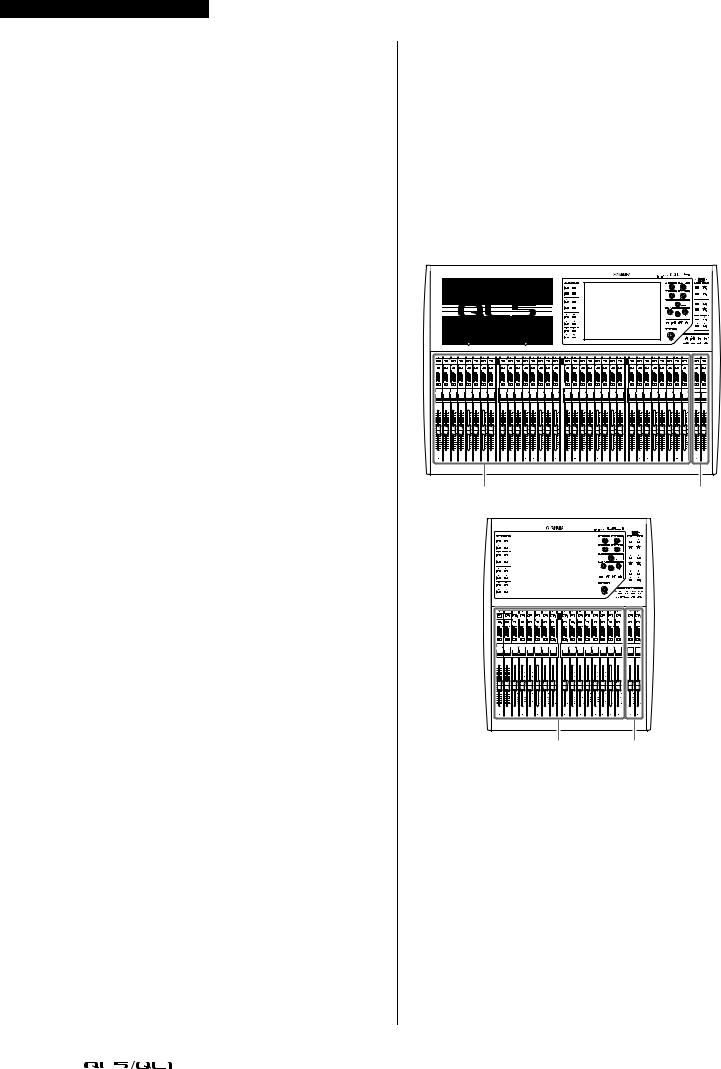
About the models
The QL series is available in two models: QL5 and QL1. Model differences are shown in the table below.
|
Analog |
Analog |
Monaural |
|
|
|
input |
Channel strips |
|||
|
inputs |
outputs |
|||
|
channels |
|
|||
|
|
|
|
||
|
|
|
|
|
|
QL5 |
32 |
16 |
64 |
Block A/B: 32 |
|
Master section: 2 |
|||||
|
|
|
|
||
|
|
|
|
|
|
QL1 |
16 |
8 |
32 |
Block A/B: 16 |
|
Master section: 2 |
|||||
|
|
|
|
||
|
|
|
|
|
• QL5 |
|
Block A/B |
Master section |
• QL1 |
|
|
|
|
|
|
|
|
|
|
|
|
|
|
|
|
|
|
|
|
|
|
|
|
|
|
|
|
|
|
|
|
|
|
|
|
|
|
|
|
|
|
|
|
|
|
|
|
|
|
|
|
|
|
|
|
|
|
|
|
|
|
|
|
|
|
|
|
|
|
|
|
|
|
|
|
|
|
|
|
|
|
|
|
|
|
|
|
|
|
|
|
|
|
|
|
|
|
|
|
|
|
|
|
|
|
|
|
|
|
|
|
|
|
|
|
|
|
|
|
|
|
|
|
|
|
|
|
|
|
|
|
|
|
|
|
|
|
|
|
|
|
|
|
|
|
|
|
|
|
|
|
|
|
|
|
|
|
|
|
|
|
|
|
|
|
|
|
|
|
|
|
|
|
|
|
|
|
|
|
|
|
|
|
|
|
|
|
|
|
|
|
|
|
|
|
|
|
|
|
|
|
|
|
|
|
|
|
|
|
|
|
|
|
|
|
|
|
|
|
|
|
|
|
|
|
|
|
|
|
|
|
|
|
|
|
|
|
|
|
|
|
|
|
|
|
|
|
|
|
|
|
|
|
|
|
|
|
|
|
|
|
|
|
|
|
|
|
|
|
|
|
|
|
|
|
|
|
|
|
|
|
|
|
|
|
|
|
|
|
|
|
|
|
|
|
|
|
|
|
|
|
|
|
|
|
|
|
|
|
|
|
|
|
|
|
|
|
|
|
|
|
|
|
|
|
|
|
|
|
|
|
|
|
|
|
|
|
|
|
|
|
|
|
|
|
|
|
|
|
|
|
|
|
|
|
|
|
|
|
|
|
|
|
|
|
|
|
|
|
|
|
|
|
|
|
|
|
|
|
|
|
|
|
|
|
|
|
|
|
|
|
|
|
|
|
|
|
|
|
|
|
|
|
|
|
|
|
|
|
|
|
|
|
|
|
|
|
|
|
|
|
|
|
|
|
|
|
|
|
|
|
|
|
|
|
|
|
|
|
|
|
|
|
|
|
|
|
|
|
|
|
|
|
|
|
|
|
|
|
|
|
|
|
|
|
|
|
|
|
|
|
|
|
|
|
|
|
|
|
|
|
|
|
|
|
|
|
|
|
|
|
|
|
|
|
|
|
|
|
|
|
|
|
|
|
|
|
|
|
|
|
|
|
|
|
|
|
|
|
|
|
|
|
|
|
|
|
|
|
|
|
|
|
|
|
|
|
|
|
|
|
|
|
|
|
|
|
|
|
|
|
|
|
|
|
|
|
|
|
|
|
|
|
|
|
|
|
|
|
|
|
|
|
|
|
|
|
|
|
|
|
|
|
|
|
|
|
|
|
|
|
|
|
|
|
|
|
|
|
|
|
|
|
|
|
|
|
|
|
|
|
|
|
|
|
|
|
|
|
|
|
|
|
|
|
|
|
|
|
|
|
|
|
|
|
|
|
|
|
|
|
|
|
|
|
|
|
|
|
|
|
|
|
|
|
|
|
|
|
|
|
|
|
|
|
|
|
|
|
|
|
|
|
|
|
|
|
|
|
|
|
|
|
|
|
|
|
|
|
|
|
|
|
|
|
|
|
|
|
|
|
|
|
|
|
|
|
|
|
|
|
|
|
|
|
|
|
|
|
|
|
|
|
|
|
|
|
|
|
|
|
|
|
|
|
|
|
|
|
|
|
|
|
|
|
|
|
|
|
|
|
|
|
|
|
|
|
|
|
|
|
|
|
|
|
|
|
|
|
|
|
|
|
|
|
|
|
|
|
|
|
|
|
|
|
|
|
|
|
|
|
|
|
|
|
|
|
|
|
|
|
|
|
|
|
|
|
|
|
|
|
|
|
|
|
|
|
|
|
|
|
|
|
|
|
|
|
|
|
|
|
|
|
|
|
|
|
|
|
|
|
|
|
|
|
|
|
|
|
|
|
|
|
|
|
|
|
|
|
|
|
|
|
|
|
|
|
|
|
|
|
|
|
|
|
|
|
|
|
|
|
|
|
|
|
|
|
|
|
|
|
|
|
|
|
|
|
|
|
|
|
|
|
|
|
|
|
|
|
|
|
|
|
|
|
|
|
|
|
|
|
|
|
|
|
|
|
|
|
|
|
|
|
|
|
|
|
|
|
|
|
|
|
|
|
|
|
|
|
|
|
|
|
|
|
|
|
|
|
|
|
|
|
|
|
|
|
|
|
|
|
|
|
|
|
|
|
|
|
|
|
|
|
|
|
|
|
|
|
|
|
|
|
|
|
|
|
|
Block A/B |
|
|
Master section |
||||||||||||||||||||||
10 |
|
Owner’s Manual |
|
|
|

Controls and functions
Controls and functions
Top panel
The top panel of the QL series is divided into the following sections.
2 |
3 |
4 |
5 |
|
|
|
6 |
|
|
|
7 |
1 (Block A/B) |
|
|
8 |
1 Channel Strip section page 12
2 SENDS ON FADER section page 12
3 Display section page 13
4 Selected Channel section page 13
5 USB connector page 15
6 USER DEFINED KEYS section page 14
7 FADER BANK section page 14
8 Master section page 14
NOTE
This illustration shows the top panel of the QL5.
Owner’s Manual 11
Controls and functions
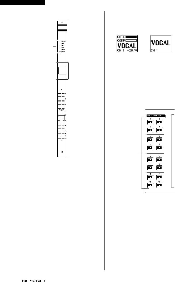
Channel Strip section
1


2


3 |
4


5
6
7

1[SEL] key
Selects the channel that will be controlled in the Channel Strip section and on the touch screen. When a channel is selected, the key LED will light. If you control an ST IN channel in the Channel Strip section, the L channel will be routed to an odd-numbered channel, and the R channel will be routed to the adjacent even-numbered channel. If you control the custom fader bank, and if you assign L/R channels, the selected object of control will alternate between the L and R channels each time you press the [SEL] key.
NOTE
If you assign either the L or R channel, this key will simply select the channel.
2[CUE] key
Selects the channel to be cue-monitored. If cue is on, the LED will light.
3Meter LEDs
Indicate the channel level.
4[ON] key
Switches the channel on or off. If a channel is on, the key LED will light. In SENDS ON FADER mode, this is an on/off switch for signals sent from each channel to the currently-selected MIX/MATRIX bus.
5Channel name display
Indicates the channel name, fader value, etc. You can set the display so that it will indicate only the channel name. The information to be shown can be specified in the USER SETUP screen PREFERENCE tab.
6Channel color indicator
Lights in the channel color specified on the PATCH/NAME screen. You can select the channel color from nine options, including OFF.
7Fader
Adjusts the input/output level of the channel. In SENDS ON FADER mode, this fader adjusts the send level of the signal from each channel to the currently-selected MIX/MATRIX bus.
SENDS ON FADER section
1
1MIX/MATRIX buses [1]–[16]
For selecting the MIX/MATRIX buses whose send levels will be adjusted in the Selected Channel section. The LED of the key corresponding to the currently selected bus will light (or flash, in the case of a MATRIX bus).
In SENDS ON FADER mode, these keys select a MIX/MATRIX bus as the send-destination. In this case, the LED of the key corresponding to the currently selected bus will flash, and the LED of keys corresponding to selectable buses will light. For MATRIX buses, the [9]–[16] keys will be dark and cannot be selected.
12 |
|
Owner’s Manual |
|
|
|
Display section
This is a touch screen that you can operate by touching the surface of the screen. You can touch your finger to the screen to select menus or set parameters. Please note that you cannot operate the unit by touching multiple points simultaneously.
NOTICE
Never use a sharp or pointed object such as your fingernail to operate the touch panel. Doing so may damage the screen and render the touch functions inoperable.
NOTE
If the touch screen becomes dirty, wipe it with a soft dry cloth.
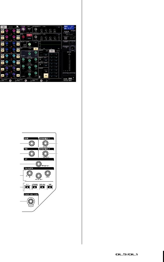
Selected Channel section
This section enables you to set the mix parameters for the currently-selected channel.
1 |
3 |
2 |
4 |
5 |
|
6 |
|
7 |
|
8 |
|
1[GAIN] knob
Adjusts the head amp’s analog gain for an input channel.
Alternately, it adjusts the digital gain if GAIN KNOB FUNCTION is set to DIGITAL GAIN in the PREFERENCE tab of the USER SETUP screen.
This knob has no effect for other types of channels.
Top panel
NOTE
•The PAD will be switched on or off internally when the HA analog gain is adjusted between +17dB and +18dB. Keep in mind that noise may be generated when using phantom power if there is a difference between the hot and cold output impedance of an external device connected to the INPUT connector.
2[PAN] knob
When a monaural channel is selected, this knob adjusts the panning of the signal sent to the STEREO bus.
When a stereo channel is selected, this knob adjusts the PAN or left/right balance, whichever is selected.
3[DYNAMICS 1] knob
4[DYNAMICS 2] knob
Adjust the THRESHOLD parameter of the gate, compressor, etc.
The [DYNAMICS 2] knob has no effect if the MIX, MATRIX, STEREO, or MONO channel is selected.
5[HPF] knob
Adjusts the HPF cutoff frequency for an input channel. It has no effect on other types of channels.
6EQ [Q], EQ [FREQUENCY], EQ [GAIN] knobs
For each band of the four-band EQ, these knobs adjust the Q, center frequency (cutoff frequency), and gain.
Press the EQ [Q] and EQ [GAIN] knobs simultaneously to reset the GAIN setting for each band to the default value (0.0dB).
7EQ [LOW] key/EQ [LOW–MID] key/EQ [HIGH–MID] key/EQ [HIGH] key
These keys select an EQ band that is controlled by the knobs located above the keys. Press and turn the EQ [Q] knob to switch between SHELVING, HPF (OUT only), and LPF.
8[TOUCH AND TURN] knob
You can press a desired knob in the touch screen and then use this knob to operate it. The LED below this knob indicates the color of the knob selected on the touch screen.
Owner’s Manual 13
Controls and functions
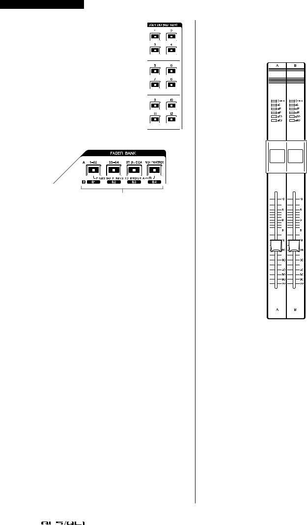
USER DEFINED KEYS section
USER DEFINED keys [1]–[12]
Execute functions as assigned by the user (scene changes, switching the talkback or internal oscillator on/off, etc.). Make these assignments in the USER SETUP screen.
FADER BANK section
1
1Bank Select keys [1–32]/[33–64]/ [STIN/DCA]/[MIX/MATRIX]
These keys switch the channel faders controlled in the Channel Strip section.
Press the [1–32] key and [MIX/MATRIX] key simultaneously to switch between fader bank A and custom fader bank B.
For details on the custom fader banks, refer to page 22.
Master section
This section is similar to the Channel Strip section, and enables you to control the principal parameters of the assigned channels. When the unit is in the default state, STEREO/MONO channels are assigned.
1


2


3


4
5

6


1[SEL] key
Selects the channel you wish to control. Pressing this key will cause the channel LED to light up, and you will be able to control the channel in both the Selected Channel section and on the touch screen. If the STEREO bus has been assigned, the selected object of control will alternate between the L and R channels each time you press the [SEL] key.
2[CUE] key
Selects the channel to be cue-monitored. If cue is on, the LED will light.
3[ON] key
Switches the channel on or off. If a channel is on, the key LED will light.
If MONITOR has been assigned, this key switches the monitor output on or off.
4Channel name display
5Channel color indicator
Same as that in the Channel Strip section.
14 |
|
Owner’s Manual |
|
|
|
6Fader
Adjusts the output level of the channel.
If MONITOR has been assigned, this fader adjusts the monitor output level.
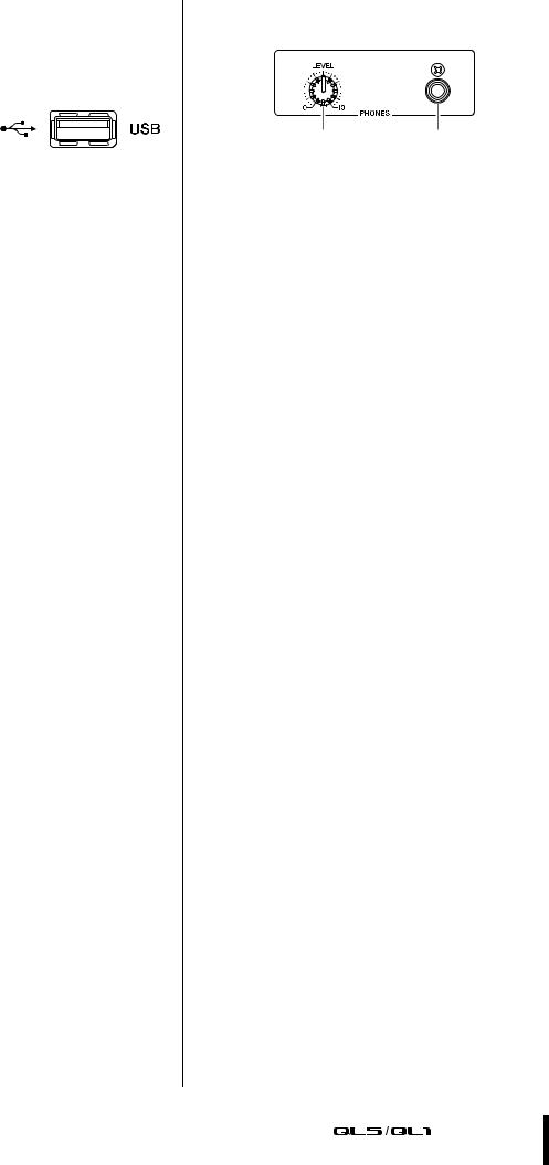
USB connector
You can connect a USB flash drive to the USB
connector to record or play audio files, and to save or load internal data.
The Help file displayed on the unit screen is also loaded from a connected USB flash drive.
You can also save “User authentication key” data on a USB flash drive. This determines the user level and limits the functionality to which each user has access.
NOTE
Operation is guaranteed only for a connection with a USB flash drive.
USB flash drive capacities and formats
The operation of USB flash drives with capacities of up to 32GB has been verified.
(However, this does not guarantee operation of all USB flash drives.)
The FAT16 and FAT32 formats are supported.
Prevention of accidental erasure
Some USB flash drives have a write-protect setting that lets you prevent data from being erased accidentally. If your flash drive contains important data, it is a good idea to use the write-protect setting to prevent accidental erasure.
On the other hand, you will need to make sure that your USB flash drive’s write-protect setting is turned off before you save data onto it.
NOTICE
An ACCESS indicator appears in the function access area while data is being accessed (saved, loaded, or deleted). Do not disconnect the USB flash drive or power-off the QL unit while this indicator is shown. Doing so may damage your flash drive, or may damage the data in the QL unit or on your media device.
Front panel
Front panel
12
1PHONES LEVEL knob
Adjusts the level of the signal output from the PHONES OUT jack.
2PHONES Out (headphone output) jack
Lets you monitor the MONITOR OUT or CUE signal.
Owner’s Manual 15
Controls and functions
Rear panel
2 |
1 |
3 |
4 |
5 6 7 |
8 |
9 |
0A |
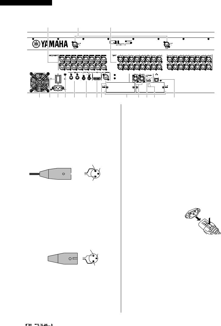
1LAMP connectors
Four-pin female XLR output jacks that supply power to separately-sold gooseneck lamps (such as the Yamaha LA1L). (The QL5 includes these connectors at two locations. The QL1 includes one.)
2OMNI OUT jacks
XLR-3-32 male output jacks for outputting analog audio signals. (The QL5 has 16 of these jacks. The QL1 has 8.) These jacks are used mainly to output the signals of MIX channels or MATRIX channels. The nominal output level is +4dBu.
Female XLR plug |
2 (Hot) |
|||||||||
|
|
3 (Cold) |
||||||||
|
|
|
|
|
|
|
|
|
|
|
|
|
|
|
|
|
|
|
|
|
|
|
|
|
|
|
|
|
|
|
|
|
|
|
|
|
|
|
|
|
|
|
|
|
|
|
|
|
|
|
|
|
|
|
|
|
|
|
|
|
|
|
|
|
|
1 (Ground)
NOTE
•The nominal output level of the OMNI OUT jacks is +4dBu (maximum level +24dBu), but if necessary, this can be changed to –2dBu (maximum level +18dBu) by setting an internal switch (a fee will be charged). For details, contact a Yamaha service center listed at the end of the owner’s manual.
3INPUT jacks
Balanced XLR-3-31 female input jacks for inputting analog audio signals from line level devices or microphones. (The QL5 has 32 of these jacks, and the QL1 has 16.) The input level range is from
–62dBu to +10dBu.
Male XLR connector |
1 (Ground) |
||||||||
|
|
3 (Cold) |
|||||||
|
|
|
|
|
|
|
|
|
|
|
|
|
|
|
|
|
|
|
|
|
|
|
|
|
|
|
|
|
|
2 (Hot)
4Exhaust port
The QL series consoles have cooling fans. Please be sure that you do not block the air intakes or exhaust vents.
B C D E F
5| /  (Power Switch)
This switch turns the power on/off (|/ ).
).
 Caution
•Rapidly turning the unit on and off in succession can cause it to malfunction. After turning the unit off, wait for at least 6 seconds before turning it on again.
•Even when the power switch is turned off, a small amount of current is flowing through the unit. If you plan not to use the unit for a long period of time, remove the power cable from the AC outlet.
6AC IN connector
Connect the supplied AC power cord here. First connect the AC power cable to the QL unit, then insert the power cable plug into an AC power outlet.
Insert the cable plug all the way until it locks in securely. The supplied AC power cable features a V-lock mechanism via a latch, which prevents the power cable from coming off accidentally.
 Caution
Be sure to turn the power off before connecting or disconnecting the power cable.
To disconnect the power cable, remove it while pressing the latch on the plug.
7Grounding screw
The supplied AC power cable is a 3-wire type. Therefore, if the AC outlet used is properly grounded, the QL will be grounded as well. Also, grounding this screw may effectively eliminate noise such as hum and interference.
16 |
|
Owner’s Manual |
|
|
|

Rear panel
8MIDI IN/OUT connectors
Used to transmit and receive MIDI messages to and from external MIDI devices. The MIDI IN connector receives messages from an external device, and the MIDI OUT connector transmits messages from the QL unit.
These are used mainly to record QL parameter operations or scene/library selections on an external device, or to control QL parameters from an external device.
9WORD CLOCK IN/OUT connectors
BNC connectors used to transmit and receive word clock signals to and from an external device. The WORD CLOCK IN connector features internal 75-ohm termination.
0GPI connector
D-sub 15-pin female connector that allows communication (5-in, 5-out) with a GPI-equipped external device.
ADIGITAL OUT connector
An AES/EBU (XLR-3-32 male) jack that outputs the digital audio signal of a desired channel in AES/EBU format. This is used mainly to output the signal of the STEREO/MONO channel.
BSLOT 1–2
Allow for the installation of separately-sold DSP cards, or mini-YGDAI I/O cards to expand the number of input/output ports.
CDante PRIMARY/SECONDARY connectors
Used to connect to other Dante audio network devices, such as an Rio3224-D I/O device.
Use standard Ethernet cables with Neutrik etherCON CAT5e compatible RJ-45 plugs.
DLINK/ACT indicators
These indicators show the communication status of the PRIMARY and SECONDARY connectors.
They flash rapidly if the Ethernet cables are connected properly.
E1G Indicators
These indicators light when the Dante network is functioning as Giga-bit Ethernet.
FNETWORK connector
This RJ-45 connector allows the QL unit to be connected to a computer via an Ethernet cable (CAT5e or higher recommended). This connector is used mainly to control mix parameters or to edit scene memories and libraries from the dedicated “QL Editor” application program or the “QL StageMix” iPad application.
Owner’s Manual 17
Touch screen
Touch screen
Basic touch screen operations
This section explains the basic procedures you can perform on the QL’s touch screen.
Pressing the touch screen
You will mainly use this operation to switch screens and pages, to select parameters to be operated, and to turn buttons on/off. Certain buttons let you specify a number based on the area of the button itself that you touch.
NOTE
Typically, you will press a top panel key once, but in certain cases you can access special functions by rapidly pressing a key twice in succession.
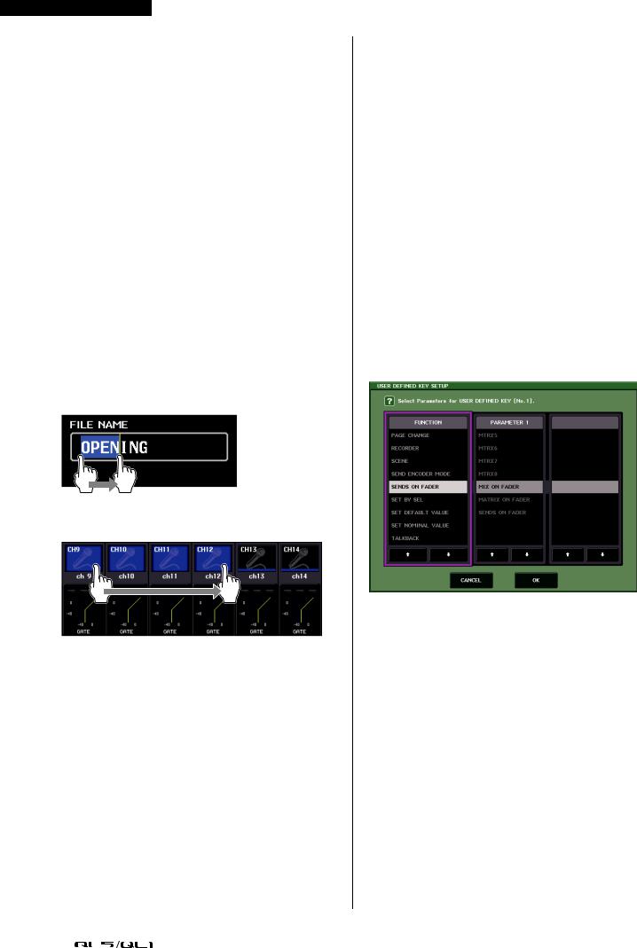
Multiple selection (specifying a range)
While pressing your finger on the touch panel, move it in the left or right direction to specify a range within a character string. You will use this technique primarily when assigning a name to a scene or library.
For the channel select buttons, you can select multiple buttons by moving your finger across the touch screen while continuing to press down.
NOTE
This makes it easy to select a range of buttons to be turned on or off together.
Using the knobs on the top panel
The knobs on the top panel are rotated to change the value of the corresponding parameter. Also, by pressing a knob, you can recall a specific screen.
For certain parameters, you can adjust the value in finer steps (greater detail) by simultaneously holding down the knob and rotating it.
Using the [TOUCH AND TURN] knob
The [TOUCH AND TURN] knob is used to operate the knobs selected for operation in the touch screen. Press the touch screen to select the knob you want to operate. When you press a knob, a highlight outline is displayed around that knob. Turn the [TOUCH AND TURN] knob to adjust the value for the corresponding parameter.
NOTE
Pressing certain knobs a second time while the outline is displayed will open a screen in which you can make additional detailed settings.
On-screen user interface
The section below explains various user interface components that appear in the touch screen, and how to use them. Examples of screens appearing on the touch screen are shown below.
USER DEFINED KEY SETUP window
Displayed when selecting items from a list, such as a list of USER DEFINED keys.
The constantly highlighted item in the center is the selected item. Press the  /
/ located below the list to scroll the list upward or downward.
NOTE
•You can also scroll the list up or down by using the [TOUCH AND TURN] knob.
•If there is more than one list in the screen, your operations will apply to the list enclosed in a white frame.
18 |
|
Owner’s Manual |
|
|
|
Loading...