


 Loading...
U
R-N602
Network Receiver
Réseau Ampli-Tuner
OWNER’S MANUAL
MODE D’EMPLOI
IMPORTANT SAFETY INSTRUCTIONS
CAUTION |
RISK OF ELECTRIC |
SHOCK DO NOT OPEN |
CAUTION: TO REDUCE THE RISK OF |
ELECTRIC SHOCK, DO NOT REMOVE |
COVER (OR BACK). NO USER-SERVICEABLE |
PARTS INSIDE. REFER SERVICING TO |
QUALIFIED SERVICE PERSONNEL. |
• Explanation of Graphical Symbols
The lightning flash with arrowhead symbol, within an equilateral triangle, is intended to alert you to the presence of uninsulated “dangerous voltage” within the product’s enclosure that may be of sufficient magnitude to constitute a risk of electric shock to persons.
The exclamation point within an equilateral triangle is intended to alert you to the presence of important operating and maintenance (servicing) instructions in the literature accompanying the appliance.
IMPORTANT
Please record the serial number of this unit in the space below. MODEL:
Serial No.:
The serial number is located on the rear of the unit. Retain this Owner’s Manual in a safe place for future reference.
1Read these instructions.
2Keep these instructions.
3Heed all warnings.
4Follow all instructions.
5Do not use this apparatus near water.
6Clean only with dry cloth.
7Do not block any ventilation openings. Install in accordance with the manufacturer’s instructions.
8Do not install near any heat sources such as radiators, heat registers, stoves, or other apparatus (including amplifiers) that produce heat.
9Do not defeat the safety purpose of the polarized or grounding-type plug. A polarized plug has two blades with one wider than the other. A grounding type plug has two blades and a third grounding prong. The wide blade or the third prong are provided for your safety. If the provided plug does not fit into your outlet, consult an electrician for replacement of the obsolete outlet.
10Protect the power cord from being walked on or pinched particularly at plugs, convenience receptacles, and the point where they exit from the apparatus.
11Only use attachments/accessories specified by the manufacturer.
12Use only with the cart, stand, tripod,
bracket, or table specified by the manufacturer, or sold with the apparatus. When a cart is used, use caution when moving the cart/apparatus combination to avoid injury from tip-over.
13Unplug this apparatus during lightning storms or when unused for long periods of time.
14Refer all servicing to qualified service personnel. Servicing is required when the apparatus has been damaged in any way, such as power-supply cord or plug is damaged, liquid has been spilled or objects have fallen into the apparatus, the apparatus has been exposed to rain or moisture, does not operate normally, or has been dropped.
We Want You Listening For A Lifetime
Yamaha and the Electronic Industries Association’s Consumer Electronics Group want you to get the most out of your equipment by playing it at a safe level. One that lets the sound come through loud and clear without annoying blaring or distortion – and, most importantly, without affecting your sensitive hearing. Since hearing damage from loud sounds is often undetectable until it is too late, Yamaha and the Electronic Industries Association’s Consumer Electronics Group recommend you to avoid prolonged exposure from excessive volume levels.
English
i En
Important safety instructions
FCC INFORMATION (for US customers)
1 IMPORTANT NOTICE: DO NOT MODIFY THIS |
Compliance with FCC regulations does not guarantee |
|
UNIT! |
that interference will not occur in all installations. If |
|
This product, when installed as indicated in the |
this product is found to be the source of interference, |
|
instructions contained in this manual, meets FCC |
which can be determined by turning the unit “OFF” |
|
requirements. Modifications not expressly approved by |
and “ON”, please try to eliminate the problem by using |
|
Yamaha may void your authority, granted by the FCC, |
one of the following measures: |
|
to use the product. |
Relocate either this product or the device that is being |
|
2 IMPORTANT: When connecting this product to |
||
affected by the interference. |
||
accessories and/or another product use only high quality |
||
Utilize power outlets that are on different branch |
||
shielded cables. Cable/s supplied with this product MUST |
||
be used. Follow all installation instructions. Failure to |
(circuit breaker or fuse) circuits or install AC line |
|
follow instructions could void your FCC authorization to |
filter/s. |
|
use this product in the USA. |
In the case of radio or TV interference, relocate/ |
|
3 NOTE: This product has been tested and found to |
reorient the antenna. If the antenna lead-in is 300 ohm |
|
comply with the requirements listed in FCC |
ribbon lead, change the lead-in to coaxial type cable. |
|
Regulations, Part 15 for Class “B” digital devices. |
If these corrective measures do not produce |
|
Compliance with these requirements provides a |
||
satisfactory results, please contact the local retailer |
||
reasonable level of assurance that your use of this |
||
authorized to distribute this type of product. If you can |
||
product in a residential environment will not result in |
||
not locate the appropriate retailer, please contact |
||
harmful interference with other electronic devices. |
||
Yamaha Corporation of America A/V Division, 6600 |
||
This equipment generates/uses radio frequencies and, |
||
Orangethorpe Avenue, Buena Park, CA 90620, USA. |
||
if not installed and used according to the instructions |
||
The above statements apply ONLY to those products |
||
found in the users manual, may cause interference |
||
harmful to the operation of other electronic devices. |
distributed by Yamaha Corporation of America or its |
|
|
subsidiaries. |
FCC CAUTION
Change or modifications not expressly approved by the party responsible for compliance could void the user’s authority to operate the equipment.
FOR CANADIAN CUSTOMERS
To prevent electric shock, match wide blade of plug to wide slot and fully insert.
CAN ICES-3(B)/NMB-3(B)
COMPLIANCE INFORMATION STATEMENT
(DECLARATION OF CONFORMITY PROCEDURE)
Responsible Party: |
Yamaha Corporation of America A/V Division |
Address: |
6600 Orangethorpe Avenue, Buena Park, CA |
|
90620, USA |
Telephone: |
1-714-522-9011 |
Type of Equipment: |
Network Receiver |
Model Name: |
R-N602 |
This device complies with Part 15 of FCC Rules and Industry Canada licence-exempt RSS standard(s).
Operation is subject to the following two conditions:
(1)this device may not cause interference, and
(2)this device must accept any interference, including interference that may cause undesired operation of this device.
NOTICE
This equipment has been tested and found to comply with the limits for a Class B digital device, pursuant to part 15 of the FCC Rules. These limits are designed to provide reasonable protection against harmful interference in a residential installation. This equipment generates, uses and can radiate radio frequency energy and, if not installed and used in accordance with the instructions, may cause harmful interference to radio communications. However, there is no guarantee that interference will not occur in a particular installation. If this equipment does cause harmful interference to radio or television reception, which can be determined by turning the equipment off and on, the user is encouraged to try to correct the interference by one or more of the following measures:
-Reorient or relocate the receiving antenna.
-Increase the separation between the equipment and receiver.
-Connect the equipment into an outlet on a circuit different from that to which the receiver is connected.
-Consult the dealer or an experienced radio/TV technician for help.
This equipment complies with FCC/IC radiation exposure limits set forth for an uncontrolled environment and meets the FCC radio frequency (RF) Exposure Guidelines in Supplement C to OET65 and RSS-102 of the IC radio frequency (RF) Exposure rules. This equipment should be installed and operated keeping the radiator at least 20cm or more away from person’s body (excluding extremities: hands, wrists, feet and ankles).
This transmitter must not be co-located or operated in conjunction with any other antenna or transmitter.
ii En

Caution: Read this before operating your unit.
1To assure the finest performance, please read this manual carefully. Keep it in a safe place for future reference.
2Install this sound system in a well ventilated, cool, dry, clean place – away from direct sunlight, heat sources, vibration, dust, moisture, and/or cold. For proper ventilation, allow the following minimum clearances.
Top: 30 cm (11-3/4 in) Rear: 20 cm (7-7/8 in) Sides: 20 cm (7-7/8 in)
3Locate this unit away from other electrical appliances, motors, or transformers to avoid humming sounds.
4Do not expose this unit to sudden temperature changes from cold to hot, and do not locate this unit in an environment with high humidity (i.e. a room with a humidifier) to prevent condensation inside this unit, which may cause an electrical shock, fire, damage to this unit, and/or personal injury.
5Avoid installing this unit where foreign objects may fall onto this unit and/or this unit may be exposed to liquid dripping or splashing. On the top of this unit, do not place:
–Other components, as they may cause damage and/or discoloration on the surface of this unit.
–Burning objects (i.e. candles), as they may cause fire, damage to this unit, and/or personal injury.
–Containers with liquid in them, as they may fall and liquid may cause electrical shock to the user and/or damage to this unit.
6Do not cover this unit with a newspaper, tablecloth, curtain, etc. in order not to obstruct heat radiation. If the temperature inside this unit rises, it may cause fire, damage to this unit, and/or personal injury.
7Do not plug in this unit to a wall outlet until all connections are complete.
8Do not operate this unit upside-down. It may overheat, possibly causing damage.
9Do not use force on switches, knobs and/or cords.
10When disconnecting the power cable from the wall outlet, grasp the plug; do not pull the cable.
11Do not clean this unit with chemical solvents; this might damage the finish. Use a clean, dry cloth.
12Only voltage specified on this unit must be used. Using this unit with a higher voltage than specified is dangerous and may cause fire, damage to this unit, and/or personal injury. Yamaha will not be held responsible for any damage resulting from use of this unit with a voltage other than specified.
13To prevent damage by lightning, keep the power cord disconnected from a wall outlet or the unit during a lightning storm.
14Do not attempt to modify or fix this unit. Contact qualified Yamaha service personnel when any service is needed. The cabinet should never be opened for any reasons.
15When not planning to use this unit for long periods of time (i.e. vacation), disconnect the AC power plug from the wall outlet.
16Be sure to read the “Troubleshooting” section in the owner’s manual on common operating errors before concluding that this unit is faulty.
17Before moving this unit, press Adownward to turn off this unit and then disconnect the AC power plug from the AC wall outlet.
18Condensation will form when the surrounding temperature changes suddenly. Disconnect the power cable from the outlet, then leave this unit alone.
19When using this unit for a long time, this unit may become warm. Turn the system off, then leave this unit alone for cooling.
20Install this unit near the wall outlet and where the AC power plug can be reached easily.
21The batteries shall not be exposed to excessive heat such as sunshine, fire or the like. When you dispose of batteries, follow your regional regulations.
22Excessive sound pressure from earphones and headphones can cause hearing loss.
This unit is not disconnected from the AC power source as long as it is connected to the wall outlet, even if this unit itself is turned off by A. This state is called the standby mode. In this state, this unit is designed to consume a very small quantity of power.
WARNING
TO REDUCE THE RISK OF FIRE OR ELECTRIC SHOCK, DO NOT EXPOSE THIS UNIT TO RAIN OR MOISTURE.
Do not use this unit within 22 cm (9 inches) of persons with a heart pacemaker implant or defibrillator implant.
This label is required to be attached to a product of which the temperature of the top cover may be hot during operation.
English
iii En

Caution: Read this before operating your unit.
■ Notes on remote controls and batteries
•Do not spill water or other liquids on the remote control.
•Do not drop the remote control.
•Do not leave or store the remote control in the following conditions:
–places of high humidity, such as near a bath
–places of high temperatures, such as near a heater or stove
–places of extremely low temperatures
–dusty places
•Insert batteries according to the polarity markings (+ and -).
•Change all batteries if you notice the operation range of the remote control narrows.
•If the batteries run out, immediately remove them from the remote control to prevent an explosion or acid leak.
•If you find leaking batteries, discard the batteries immediately, taking care not to touch the leaked material. If the leaked material comes into contact with your skin or gets into your eyes or mouth, rinse it away immediately and consult a doctor. Clean the battery compartment thoroughly before installing new batteries.
•Do not use old batteries together with new ones. This may shorten the life of the new batteries or cause old batteries to leak.
•Do not use different types of batteries (such as alkaline and manganese batteries) together. Read the packaging carefully as these different types of batteries may have the same shape and color.
•Before inserting new batteries, wipe the battery compartment clean.
•Keep the batteries in a location out of reach of children. Batteries can be dangerous if a child were to put in his or her mouth.
•If the batteries grow old, the effective operation range of the remote control decreases considerably. If this happens, replace the batteries with new one as soon as possible.
•If you plan not to use the unit for a long period of time, remove the batteries from the unit. Otherwise, the batteries will wear out, possibly resulting in a leakage of battery liquid that may damage the unit.
•Do not throw away batteries with general house waste. Dispose of them correctly in accordance with your local regulations.
Bluetooth
•Bluetooth is a technology for wireless communication between devices within an area of about 10 meters (33 ft) employing the 2.4 GHz frequency band, a band which can be used without a license.
Handling Bluetooth communications
•The 2.4 GHz band used by Bluetooth compatible devices is a radio band shared by many types of equipment. While Bluetooth compatible devices use a technology minimizing the influence of other components using the same radio band, such influence may reduce the speed or distance of communications and in some cases interrupt communications.
•The speed of signal transfer and the distance at which communication is possible differs according to the distance between the communicating devices, the presence of obstacles, radio wave conditions and the type of equipment.
•Yamaha does not guarantee all wireless connections between this unit and devices compatible with Bluetooth function.
iv En

Contents
INTRODUCTION |
|
What you can do with this unit ................................. |
2 |
Sources that can be played back on this unit ................. |
2 |
Mastering useful apps (MusicCast CONTROLLER).... |
3 |
Supplied accessories ................................................... |
4 |
Controls and functions ............................................... |
5 |
Front panel..................................................................... |
5 |
Front display .................................................................. |
7 |
Rear panel ...................................................................... |
8 |
Remote control............................................................... |
9 |
PREPARATION |
|
Connections ............................................................... |
11 |
Connecting the speakers .............................................. |
12 |
Connecting the FM and AM antennas ......................... |
13 |
Connecting the network cable ..................................... |
14 |
Preparing a wireless antenna ....................................... |
14 |
Connecting power cable .............................................. |
14 |
Connecting to network ............................................. |
15 |
Sharing the iOS device setting..................................... |
16 |
Using the WPS push button configuration .................. |
17 |
Set the wireless network connection manually............ |
18 |
Connecting a mobile device to the unit directly |
|
(Wireless Direct) ..................................................... |
19 |
Verify the network connection status .......................... |
20 |
BASIC OPERATION |
|
Playback .................................................................... |
21 |
Playing a source........................................................... |
21 |
Using the sleep timer ................................................... |
23 |
Listening to FM/AM radio....................................... |
24 |
FM/AM tuning............................................................. |
24 |
Automatic preset tuning (FM stations only)................ |
24 |
Manual tuning preset ................................................... |
25 |
Recalling a preset station ............................................. |
26 |
Clearing a preset station............................................... |
26 |
Playing back music via Bluetooth............................ |
27 |
Connecting a Bluetooth device (pairing) ..................... |
27 |
Playing back Bluetooth device contents ...................... |
27 |
Disconnecting a Bluetooth connection ........................ |
28 |
Playing back music stored on media servers |
|
(PCs/NAS) ............................................................. |
29 |
Setting the media sharing of music files...................... |
29 |
Playback of PC music contents.................................... |
30 |
Listening to Internet radio ....................................... |
32 |
Registering favorite Internet radio stations |
|
(bookmarks)............................................................. |
33 |
Playing back iPod/iTunes music via a network |
|
(AirPlay)................................................................. |
34 |
Playback of iPod/iTunes music contents ..................... |
34 |
Playing back music stored on a USB storage |
|
device ...................................................................... |
36 |
Connecting a USB storage device ............................... |
36 |
Playback of USB storage device contents ................... |
36 |
Playing back iPod music........................................... |
38 |
Connecting an iPod...................................................... |
38 |
Playback of iPod content ............................................. |
38 |
Switching information on the front display............ |
40 |
Registering the current playback song/station |
|
(Preset function) .................................................... |
41 |
Registering to a preset ................................................. |
41 |
Recalling a preset......................................................... |
41 |
ADVANCED OPERATION |
|
Configuring playback settings for different |
|
playback sources (Option menu) ......................... |
42 |
Option menu items....................................................... |
42 |
Configuring various functions (Setup menu) ......... |
43 |
Setup menu items......................................................... |
43 |
Network ....................................................................... |
44 |
Bluetooth ..................................................................... |
45 |
Max Volume ................................................................ |
46 |
Initial Volume.............................................................. |
46 |
AutoPowerStdby (Auto Power Standby)..................... |
46 |
ECO Mode ................................................................... |
46 |
Configuring the system settings |
|
(ADVANCED SETUP menu)............................... |
47 |
ADVANCED SETUP menu items .............................. |
47 |
Changing the speaker impedance setting (SP IMP.) ... |
47 |
Selecting the remote control ID (REMOTE ID).......... |
47 |
Restoring the default settings (INIT)........................... |
47 |
Updating the firmware (UPDATE) ............................. |
48 |
Checking the firmware version (VERSION)............... |
48 |
Updating the unit’s firmware via the network ....... |
49 |
ADDITIONAL INFORMATION |
|
Troubleshooting......................................................... |
50 |
Error indications on the front display..................... |
56 |
Trademarks ............................................................... |
57 |
Specifications ............................................................. |
58 |
Index ........................................................................... |
59 |
INTRODUCTION |
|
|
|
||
|
|
|
|
|
|
PREPARATION |
|
|
|
|
|
|
|
|
OPERATION |
BASIC |
|
|
|
|
|
|
|
OPERATION |
ADVANCED |
|
|
|
|
|
|
|
INFORMATION |
ADDITIONAL |
|
|
|
|
|
|
• “Note” indicates precautions for use of the unit and its feature limitations. yindicates supplementary explanations for better use. |
|
English |
• This manual explains operations using the supplied remote control. |
|
|
|
|
|
• This manual describes all the “iPod” and “iPhone” as the “iPod”. “iPod” refers to “iPod” and “iPhone”, unless otherwise specified. |
|
|
• In this manual, iOS and Android mobile devices are collectively referred to as “mobile devices”. The specific type of mobile |
|
|
device is noted in explanations as needed. |
|
|
|
|
|
1 En
What you can do with this unit
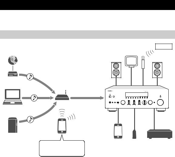
This unit is a network receiver compatible with a network source such as a media server and mobile device.
It supports playback from not only analog sources such as a CD player but also Bluetooth devices and network streaming services.
Sources that can be played back on this unit
0 FM/AM
1Internet
2Streaming service
Modem
|
Router* |
3PC |
|
5AirPlay (iTunes) |
This unit |
|
Mobile
device
4NAS
7iPod |
8USB |
9CD player etc. |
5AirPlay (iPod) |
device |
|
6Bluetooth
*You need a commercially available wireless router (access point) when you use a mobile device.
1 |
Play back the Internet radio (p. 32) |
6 |
Play back audio content from Bluetooth |
2 |
Play back the streaming service |
|
devices (p. 27) |
|
|
||
|
(see the supplement for each service.) |
7 |
Play back music files stored on your iPod |
3 |
Play back music files stored on your PC (p. 29) |
|
(p. 38) |
|
|
||
4 |
Play back music files stored on your NAS |
8 |
Play back music files stored on your USB |
|
device (p. 36) |
||
|
(p. 29) |
|
|
|
|
|
|
5 |
Play back music files stored on your iPod/ |
9 |
Play back your external component (p. 11) |
|
|
||
|
iTunes with AirPlay (p. 34) |
0 |
Listening to FM/AM radio (p. 24) |
y
For details on connecting the external devices, see “Connections” (p. 11).
2 En

What you can do with this unit
Mastering useful apps (MusicCast CONTROLLER)
You can operate and program the unit, or play streaming services via this unit, by installing the free dedicated MusicCast CONTROLLER app on a mobile device. For details, search for “MusicCast CONTROLLER” on the App Store or Google Play.
■ MusicCast CONTROLLER capabilities
•Basic operations of the unit (turn on/standby, adjust volume and select input)
•Play songs stored on computers (servers)
•Select an Internet radio station
•Play music stored on mobile devices
•Play music on streaming service
•Distribute and receive audio between the unit and other Yamaha MusicCast supported devices See MusicCast Setup Guide for details.
INTRODUCTION
English
3 En
Supplied accessories
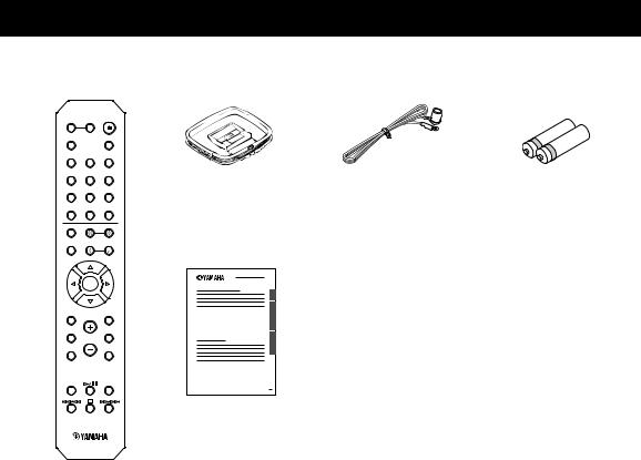
Check that the following accessories are supplied with the product.
Remote control |
AM antenna |
FM antenna |
Batteries (x2) |
|
|
|
(AA, R6, UM-3) |
SPEAKERS |
|
|
A |
B |
|
PHONO |
|
SLEEP |
COAX 1 |
COAX 2 |
BLUETOOTH |
OPT 1 |
OPT 2 |
CD |
LINE 1 |
LINE 2 |
LINE 3 |
TUNER |
NET |
USB |
BAND |
TUNING |
|
|
||
MEMORY |
PRESET |
|
|
||
|
ENTER |
|
HOME |
|
RETURN |
SETUP |
|
OPTION |
|
VOLUME |
|
MusicCast Setup Guide
NOW PLAYING |
MUTE |
REPEAT |
SHUFFLE |
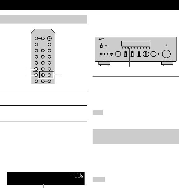
4 En
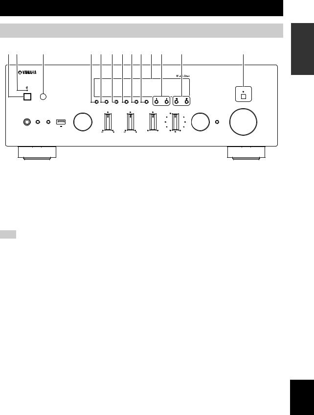
Controls and functions
Front panel
1 2 |
3 |
4 5 6 7 8 9 : A B |
C |
|||||
|
|
|
|
|
|
|
|
PURE DIRECT |
|
|
DIMMER DISPLAY |
MODE MEMORY |
CLEAR |
BAND |
PRESET |
TUNING |
|
|
|
|
|
|
|
|
|
VOLUME |
|
INPUT |
BASS |
TREBLE |
|
BALANCE |
|
LOUDNESS |
SELECT |
PUSH - ENTER
FLAT
PHONES SPEAKERS
|
|
-30dB |
A |
B |
RETURN |
|
5V 1A |
CONNECT |
|
L |
R |
INTRODUCTION
1 A (power)
Turns on/off (standby) the unit.
2 STANDBY/ON indicator
Lights up as follows: Brightly lit: Power is on Dimly lit: Standby mode
Note
In standby mode, this unit consumes a small amount of power to receive infrared signals from the remote control.
3 Remote control sensor
Receives infrared signals from the remote control.
4 DIMMER
Changes the brightness level of the front display. Choose brightness from 5 levels by pressing this button repeatedly.
5 DISPLAY
Selects the information displayed on the front display (p. 40).
6 MODE
Sets the FM band reception mode to automatic stereo or monaural (p. 24).
Switches the iPod operation modes (p. 39).
7 MEMORY
Registers the current FM/AM station as a preset when TUNER is selected as the input source (p. 25). Registers the current playback song or streaming station
as a preset when NET, USB (except iPod) are selected as the input source (p. 41).
8 CLEAR
Clears a FM/AM preset station when TUNER is selected as the input source (p. 26).
9 BAND
Switches between FM and AM (p. 24).
0 Front display
Shows information about the operational status of this unit.
A PRESET j / i
Recalls a preset FM/AM station (p. 26) or song/streaming station (p. 41).
B TUNING jj / ii
Selects the tuning frequency when TUNER is selected as the input source (p. 24).
C PURE DIRECT and indicator
Allows you to listen to a source in the purest possible sound (p. 21). The indicator above it lights up and the front display turns off when this function is turned on.
English
5 En
Controls and functions
PURE DIRECT
DIMMER DISPLAY MODE MEMORY CLEAR BAND  PRESET
 TUNING
VOLUME
INPUT BASS TREBLE BALANCE LOUDNESS SELECT
PUSH - ENTER
FLAT
PHONES |
SPEAKERS |
|
|
|
|
|
-30dB |
|
A B |
|
RETURN |
|
5V |
1A |
CONNECT |
|
|
L |
R |
D E F G H I J K L M N |
|||
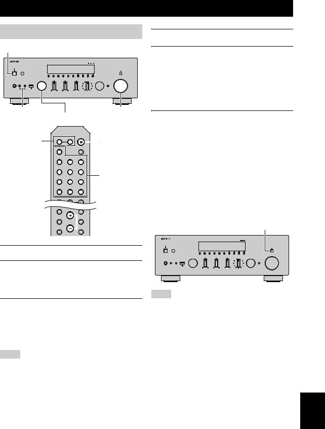
D PHONES jack
Outputs audio to your headphones for private listening.
E SPEAKERS A/B
Turns on or off the speaker set connected to the SPEAKERS A and/or SPEAKERS B terminals on the rear panel each time the corresponding button is pressed.
F USB jack
For connecting a USB storage device (p. 36) or an iPod (p. 38).
G INPUT selector
Selects the input source you want to listen to.
H BASS +/– control
Increases or decreases the low frequency response. The center position produces a flat response (p. 22).
I TREBLE +/– control
Increases or decreases the high frequency response. The center position produces a flat response (p. 22).
J BALANCE control
Adjusts the sound output balance of the left and right speakers to compensate for sound imbalances caused by speaker locations or listening room conditions (p. 22).
K LOUDNESS control
Retains a full tonal range at any volume level to compensate for the human ears’ loss of sensitivity to high and low-frequency ranges at a low volume level (p. 22).
L SELECT/ENTER (jog dial)
Turn the dial to select a numeric value or setting, and press the dial to confirm.
M RETURN
Returns to the previous indication of the front display.
CONNECT
Use to control the unit using the dedicated MusicCast CONTROLLER app for mobile devices. See MusicCast Setup Guide for details.
N VOLUME control
Increases or decreases the sound output level.
6 En

Controls and functions
Front display
1 |
2 |
3 456 7 |
8 |
9 |
STEREO TUNED |
SLEEP |
MUTE |
A |
B |
VOL. |
: |
|
: |
y
If the network connection is not set, turn the power ON to display “WAC” (Wireless Accessory Configuration) on the front panel and trigger an automatic iOS device search. See “Sharing the iOS device setting” (p. 16) for details on the iOS device and network connection.
INTRODUCTION
1 Information display
Displays the current status (such as input name).
You can switch the information that is displayed when you press DISPLAY on the front panel (p. 40).
2 STEREO
Lights up when the unit is receiving a stereo FM radio signal.
3 TUNED
Lights up when the unit is receiving an FM/AM radio station signal.
4 Signal strength indicator
Lights up when the unit connects to a wireless network or operates as an access point. The strength of the wireless network signal can be verified by the indicator status.
5 Bluetooth indicator
Lights up when the unit is connecting to a Bluetooth device.
6 Speaker indicators
“A” lights up when the SPEAKERS A output is enabled and “B” lights up when the SPEAKERS B output is enabled.
7 SLEEP
Lights up when the sleep timer is on.
8 MUTE
Blinks when audio is muted.
9 Volume indicator
Indicates the current volume.
0 Cursor indicators
Indicate the remote control cursor keys currently operational.
y
You can change the brightness level of the front display by pressing DIMMER on the front panel (p. 5).
English
7 En
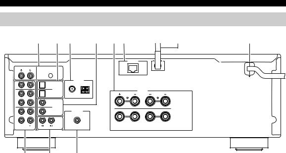
Controls and functions
Rear panel
|
1 |
2 3 |
4 |
5 6 |
7 |
8 |
|
|
|
|
|
NETWORK |
|
PHONO |
|
|
|
|
|
|
|
SIGNAL |
|
|
|
|
|
|
GND |
|
|
|
|
|
IN |
|
ANTENNA |
|
|
|
|
|
FM |
AM |
|
|
|
|
1 |
1 |
|
|
|
|
|
IN |
|
OPTICAL |
|
|
SPEAKERS |
|
|
|
|
|
|
||
|
2 |
75Ω |
|
|
|
|
2 |
|
|
|
|
|
|
|
1 |
|
|
|
A |
|
OUT |
|
COAXIAL |
|
|
|
|
IN |
|
|
|
|
|
|
|
|
|
|
|
|
|
|
2 |
SUBWOOFER |
|
|
|
|
|
|
PRE OUT |
|
|
|
|
3 |
|
|
|
|
B |
|
|
|
|
|
|
|
|
|
|
CD |
|
|
|
|
OUT |
|
|
|
|
|
|
|
LINE |
|
|
|
|
|
9 : A
1 PHONO jacks
For connecting to a turntable (p. 11).
2 OPTICAL 1/2 jacks
For connecting to audio components equipped with optical digital output (p. 11).
3 ANTENNA terminals
For connecting to FM and AM antennas (p. 13).
4 COAXIAL 1/2 jacks
For connecting to audio components equipped with a coaxial digital output (p. 11).
5SPEAKERS terminals
Used to connect speakers (p. 12).
6NETWORK jack
For connecting to a network with a network cable (p. 14).
7 Wireless antenna
For connecting to a network device wirelessly (p. 14).
8 Power cable
For connecting to an AC wall outlet (p. 14).
9 LINE 1-3 jacks
For connecting to analog audio components (p. 11).
0 CD jacks
For connecting to a CD player (p. 11).
A SUBWOOFER PRE OUT jack
For connecting to a subwoofer with built-in amplifier (p. 11).
8 En
Remote control
1
2 |
SPEAKERS |
|
|
A |
B |
|
|
|
PHONO |
|
SLEEP |
|
COAX 1 |
COAX 2 |
BLUETOOTH |
|
OPT 1 |
OPT 2 |
CD |
3 |
|
|
|
|
LINE 1 |
LINE 2 |
LINE 3 |
|
TUNER |
NET |
USB |
4 |
BAND |
|
TUNING |
|
|
||
5 |
MEMORY |
|
PRESET |
|
|
||
6 |
|
ENTER |
|
|
HOME |
|
RETURN |
7 |
|
SETUP |
OPTION |
8 |
VOLUME |
NOW PLAYING |
MUTE |
9 |
|
0 |
|
REPEAT |
SHUFFLE |
A |
|
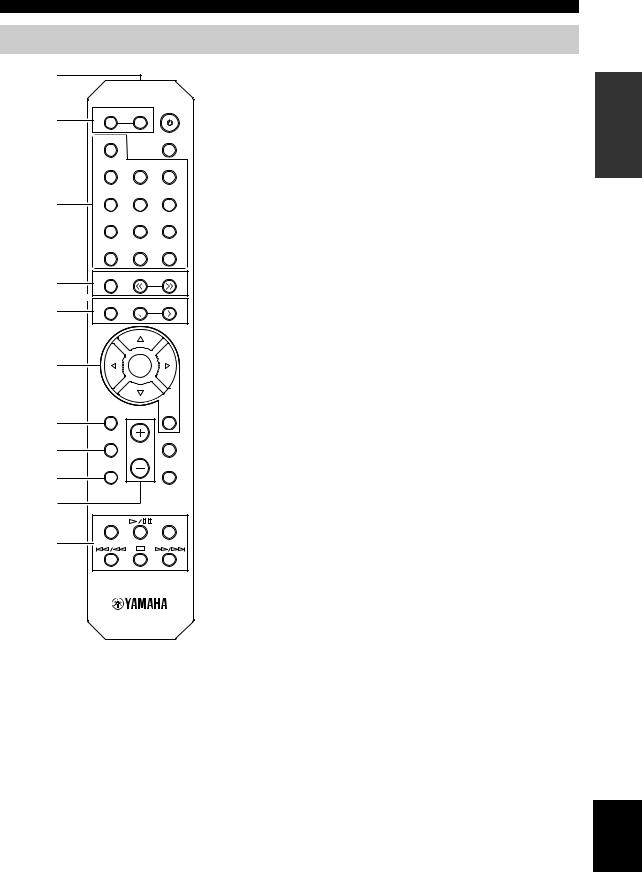
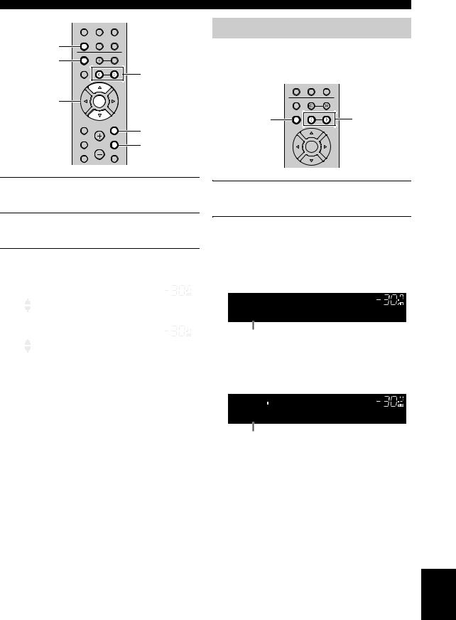
Controls and functions
1Infrared signal transmitter
Sends infrared signals.
2SPEAKERS A/B
Turns on and off the set of speakers connected to the SPEAKERS A and/or SPEAKERS B terminals on the rear panel of this unit when the corresponding key is pressed.
3 Input selection keys
Select an input source for playback.
PHONO |
PHONO jacks |
COAX 1/2 |
COAXIAL1/2 jacks |
BLUETOOTH |
Bluetooth connection |
OPT 1/2 |
OPTICAL 1/2 jacks |
CD |
CD jacks |
LINE 1-3 |
LINE 1-3 jacks |
TUNER |
FM/AM tuner |
NET |
Network source (press repeatedly to select a |
USB |
desired network source) |
USB jack (on the front panel) |
4 Radio keys
Operate the FM/AM radio (p. 24).
BAND Switches between FM and AM. TUNING jj/ii Selects the radio frequency.
5 Preset keys
MEMORY Registers the current FM/AM station as a preset when TUNER is selected as the input source (p. 25).
Registers the current playback song or streaming station as a preset when NET, USB (except iPod) are selected as the input source (p. 41).
PRESET j/i Recalls a preset FM/AM station (p. 26) or song/streaming station (p. 41).
6 Menu operation keys
Cursor keys Select a menu or a parameter.
(B/C/D/E)
ENTER Confirms a selected item. RETURN Returns to the previous state.
7 HOME
Moves up top level when selecting music files, folders, etc.
8 SETUP
Displays the “Setup” menu (p. 43).
9 NOW PLAYING
Displays music information when selecting music files, folders, etc.
0 VOLUME +/-
Adjust the volume.
A Playback keys
Let you play back and perform other operations for network sources, Bluetooth devices and USB devices.
INTRODUCTION
English
9 En
Controls and functions
SPEAKERS
A |
B |
|
PHONO |
|
SLEEP |
COAX 1 |
COAX 2 |
BLUETOOTH |
OPT 1 |
OPT 2 |
CD |
LINE 1 |
LINE 2 |
LINE 3 |
TUNER |
NET |
USB |
BAND |
TUNING |
|
|
||
MEMORY |
PRESET |
|
|
||
|
ENTER |
|
HOME |
|
RETURN |
SETUP |
|
OPTION |
|
VOLUME |
|
NOW PLAYING |
|
MUTE |
REPEAT |
|
SHUFFLE |
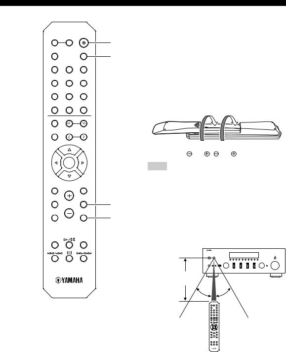
B A (power)
Turns on/off (standby) the unit.
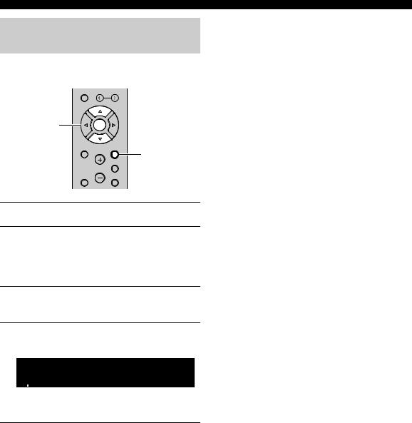
C SLEEP
BSets the sleep timer (p. 23).
D OPTION
CDisplays the “Option” menu (p. 42).
E MUTE
Mutes the audio output.
■ Installing batteries
 1 3
1 3
2

Notes
•Change all batteries if the operation range of the remote control narrows.
•Before inserting new batteries, wipe the compartment clean.
D
■ Operation range
E The remote controls transmit a directional infrared beam. Be sure to aim the remote controls directly at the remote control sensor on the front panel of this unit.
Approximately
6 m (20 ft)
30° |
30° |
Remote control
10 En
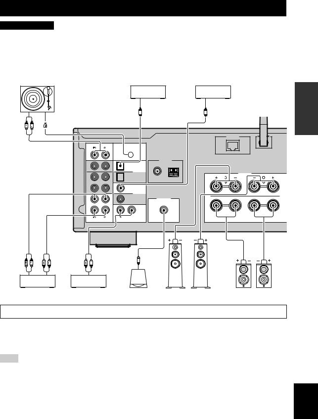
Connections
CAUTION
•Do not connect this unit or other components to the main power until all connections between components are complete.
•All connections must be correct: L (left) to L, R (right) to R, “+” to “+” and “–” to “–”. If the connections are faulty, no sound will be heard from the speakers, and if the polarity of the speaker connections is incorrect, the sound will be unnatural and lack bass. Refer to the owner’s manual for each of your components.
•Do not let bare speaker wires touch each other or any metal part of this unit. This could damage this unit and/or the speakers.
•Make sure to use RCA cables, optical cables to connect audio components.
|
Turntable |
DVD player, etc. |
|
CD player, etc. |
|
|
|
|
Audio output |
|
Audio output |
|
|
O |
(digital optical) |
C (digital coaxial) |
|
Audio |
GND |
|
|
|
|
output |
|
|
|
|
|
|
|
|
|
|
|
|
|
|
|
|
NETWORK |
|
PHONO |
|
|
|
|
|
|
SIGNAL |
|
|
|
|
|
GND |
|
|
|
|
IN |
|
ANTENNA |
|
|
|
|
FM |
AM |
|
|
|
1 |
1 |
|
||
|
|
|
|
||
|
IN |
OPTICAL |
|
SPEAKERS |
|
|
|
|
|
||
|
|
2 |
75Ω |
|
|
|
2 |
|
|
|
|
|
|
1 |
|
|
A |
OUT
COAXIAL
IN
2SUBWOOFER PRE OUT
3 |
B |
|
|
|
CD |
OUT |
|
|
LINE |
Audio |
Audio |
Audio |
|
|
|
output |
input |
output |
|
|
|
CD recorder, etc. |
CD player |
Subwoofer |
Speakers A |
Speakers B |
|
Only PCM signals can be input to the digital (OPTICAL/COAXIAL) jacks of this unit.
y
•The PHONO jacks are designed for connecting a turntable with an MM cartridge.
•Connect your turntable to the GND terminal to reduce noise in the signal. However, for some turntables, you may hear less noise without the GND connection.
Note
In order to prevent the audio signal from looping when an audio recording device is connected, the audio signal is not output from the LINE 2 (OUT) jacks when LINE 2 is selected. Similarly, the audio signal is not output from the LINE 3 (OUT) jacks when LINE 3 is selected.
PREPARATION
English
11 En
Connections
Connecting the speakers
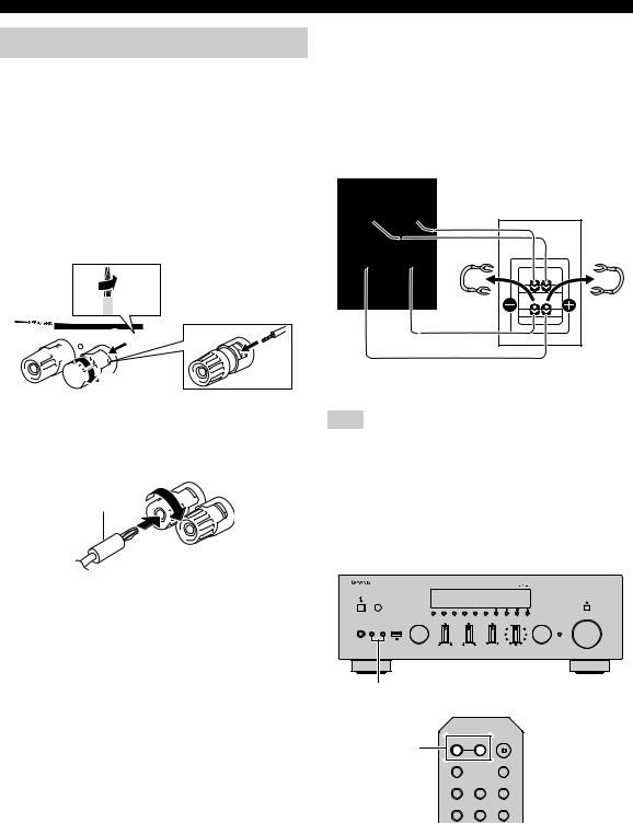
■ Connecting speaker cables
Speaker cables have two wires. One is for connecting the negative (–) terminal of the unit and the speaker, and the other is for the positive (+) terminal. If the wires are colored to prevent confusion, connect the black wire to the negative and the other wire to the positive terminal.
aRemove approximately 10 mm (3/8”) of insulation from the ends of the speaker cable and twist the bare wires of the cable firmly together.
bLoosen the speaker terminal.
cInsert the bare wires of the cable into the gap on the side (upper right or bottom left) of the terminal.
dTighten the terminal.
a10 mm (3/8")


 c
c 

 b
b 

 d
d
■ Connecting via banana plug
Tighten the knob and then insert the banana plug into the end of the corresponding terminal.
Banana plug 


■ Bi-wire connection
Bi-wire connection separates the woofer from the combined midrange and tweeter section. A bi-wire compatible speaker has four binding post terminals. These two sets of terminals allow the speaker to be split into two independent sections. With these connections, the mid and high frequency drivers are connected to one set of terminals and the low frequency driver to another set of terminals.
This unit
SPEAK
Speaker
A
B
Connect the other speaker to the other set of terminals in the same way.
Note
When making bi-wire connections, remove the shorting bridges or cables on the speaker. Refer to the speakers’ instruction manuals for more information.
y
To use the bi-wire connections, press SPEAKERS A and SPEAKERS B on the front panel or on the remote control so that both speaker indicators (“A” and “B”) light up on the front display.
PURE DIRECT
VOLUME
|
|
INPUT |
BASS |
TREBLE |
BALANCE |
LOUDNESS |
SELECT |
PHONES |
SPEAKERS |
|
|
|
FLAT |
|
|
|
|
|
|
|
|
|
-30dB |
|
A |
B |
|
|
|
|
|
|
|
|
|
L |
|
R |
|
SPEAKERS A/B
SPEAKERS A/B |
SPEAKERS |
|
|
A |
B |
|
|
|
PHONO |
|
SLEEP |
|
COAX 1 |
COAX 2 |
BLUETOOTH |
|
OPT 1 |
OPT 2 |
CD |
12 En
Connections
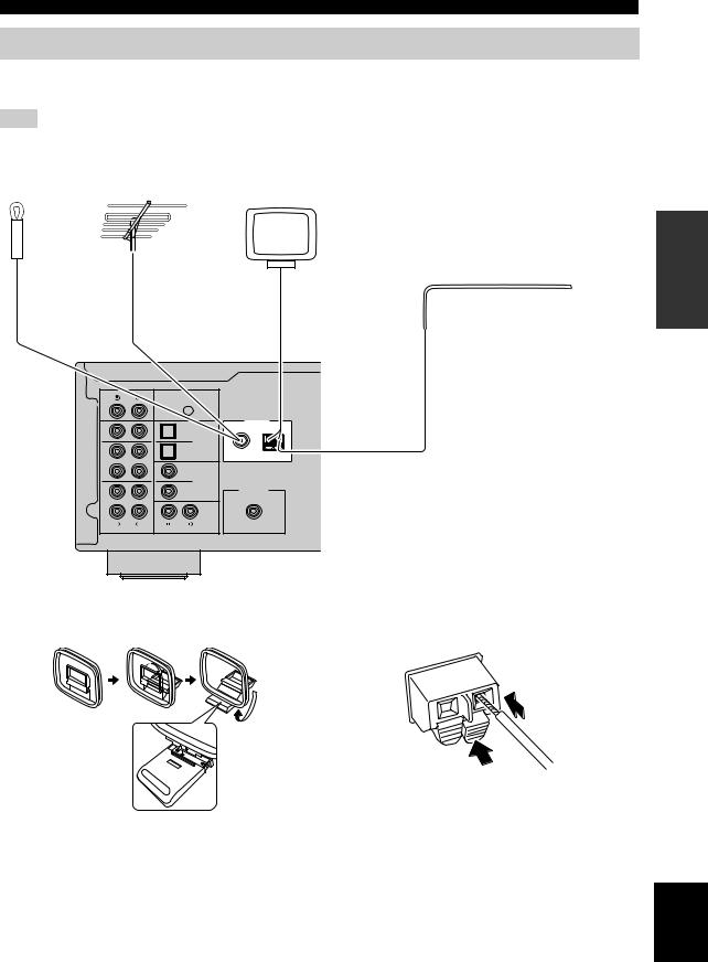
Connecting the FM and AM antennas
The antennas for receiving FM and AM broadcasts are included with this unit. In general, these antennas should provide sufficient signal strength. Connect each antenna correctly to the designated terminals.
Note
If you experience poor reception quality, install an outdoor antenna. Consult the nearest authorized Yamaha dealer or service center about outdoor antennas.
FM antenna |
or |
Outdoor |
|
(included) |
FM antenna |
||
|
AM antenna (included)
• The AM antenna should always be connected, even if an outdoor AM antenna is connected to this unit.
• The AM antenna should be placed away from this unit.
Outdoor AM antenna
Use 5 to 10 m of vinyl-covered wire extended outdoors from a window.
PREPARATION
PHONO |
|
|
|
|
|
SIGNAL |
|
|
|
|
GND |
|
|
|
IN |
|
|
ANTENNA |
|
|
FM |
AM |
||
1 |
1 |
|||
|
|
|||
IN |
|
OPTICAL |
|
|
|
|
|
||
|
2 |
75Ω |
|
|
2 |
|
|
|
1
OUT
COAXIAL
IN
2SUBWOOFER PRE OUT
3
CD
OUT
LINE
■ Assembling the supplied AM antenna |
■ Connecting the wires of the AM antenna |
2 Insert
1 Hold down
English
13 En
Connections
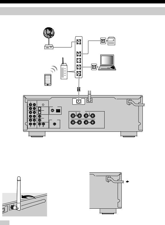
Connecting the network cable
Connect the unit to your router with a commercially-available STP network cable (CAT-5 or higher straight cable).
Internet 


Modem
Network Attached Storage
(NAS)
WAN
LAN
PC
Router |
Network cable |
|
|
Mobile device |
|
(such as iPhone) |
|
NETWORK
PHONO
SIGNAL
GND
IN |
|
|
ANTENNA |
1 |
FM |
AM |
|
1 |
|
|
|
IN |
|
OPTICAL |
SPEAKERS |
|
|
||
|
2 |
75Ω |
|
2 |
|
|
|
|
1 |
|
A |
OUT
COAXIAL
IN
2SUBWOOFER PRE OUT
3 |
B |
|
CD
OUT
LINE
This unit (rear)
Preparing a wireless antenna |
|
Connecting power cable |
If you connect the unit wirelessly, erect the wireless antenna. For information on how to connect the unit to a wireless network, see “Connecting to network” (p. 15).
After all the connections are complete, plug in the power cable.
To an AC wall outlet
WORK
Note
Do not apply excessive force on the wireless antenna. Doing so may damage the antenna.
14 En
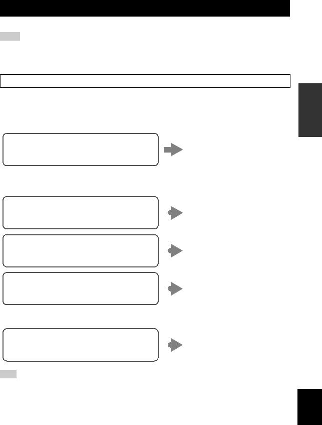
Connecting to network
There are several methods to connect the unit to a network. Select a connection method according to your environment.
Notes
•Some security software installed on your PC or the firewall settings of network devices (such as a router) may block the access of the unit to the network devices or the Internet. In these cases, configure the security software or firewall settings appropriately.
•Each server must be connected to the same subnet as the unit.
•To use the service via the Internet, broadband connection is strongly recommended.
When playing a high-resolution audio source via the network, we recommend connecting with a wired router for stable playback.
■Connecting with the MusicCast CONTROLLER app
See MusicCast Setup Guide for details.
■Connecting with the wired router
Connecting using the DHCP server function of the
You can connect to the network by
router
simply making a wired connection (p. 14)
■ Connecting with a wireless router (access point)
Connect to the network with the method listed below that corresponds to your environment.
Connecting using the Wi-Fi setting of the iOS |
|
|
Share the Wi-Fi setting of the iOS |
|
|
||
device (iPhone / iPod touch) |
|
|
device (p. 16) |
|
|
||
Connecting using WPS push button configuration |
|
|
Use the WPS push button |
on the wireless router (or access point) |
|
|
configuration (p. 17) |
|
|||
|
|
||
Connecting with a wireless router (access point) |
|
|
Set the network connection |
without WPS push button configuration |
|
|
manually (p. 18) |
|
|||
|
|
PREPARATION
■ Connecting without a wired router or wireless router (access point)
Connecting wirelessly to a mobile device |
|
Connect wirelessly with Wireless |
|
||
(Wireless Direct) |
|
Direct (p. 19) |
|
Note
When the unit is connected to the network with Wireless Direct, it cannot connect to any other wireless router (access point). To play back contents from the Internet, connect this unit to a network with a wired router or wireless router (access point).
English
15 En
Connecting to network
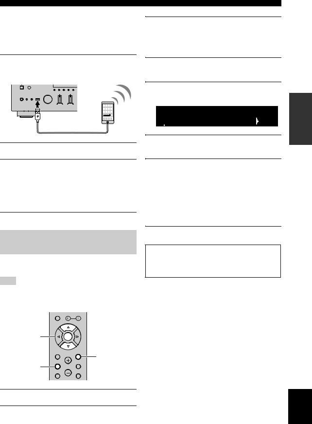
Sharing the iOS device setting
You can easily setup a wireless connection by applying the connection settings on iOS devices (iPhone/iPod touch). Before proceeding, confirm that your iOS device is connected to a wireless router (access point).
If the network connection is not set, when you turn on this unit, “WAC” (Wireless Accessory Configuration) appears on the front display, and the iOS device setting can be shared.
WAC
R-N602 XXXXXX
To share the iOS device setting, perform the network setting sharing operation on your iOS device.
MEMORY
 PRESET
Cursor keys B/ C |
ENTER |
ENTER |
|
HOME |
RETURN |
|
RETURN |
SETUP |
OPTION |
SETUP |
VOLUME |
NOW PLAYING |
MUTE |
1Press A to turn on this unit.
2Press SETUP.
3Use the cursor keys (B / C) to select
“Network” and press ENTER.
y
To return to the previous state, press RETURN.
4Use the cursor keys (B / C) to select
“Connection” and press ENTER.
5Use the cursor keys (B / C) to select
“Wireless” and press ENTER.
WIRELESS


 WPS
WPS
6Use the cursor keys (B / C) to select “Share
Setting” and press ENTER.
SHARE


 Wireless(WAC)
7Use the cursor keys (B / C) to select the desired connection method and press
ENTER.
The following connection methods are available.
|
You can apply the connection settings on the iOS |
|
Wireless |
device to the unit using a wireless connection. For |
|
details, see “Sharing the iOS device setting |
||
(WAC) |
||
wirelessly”. (You need iOS device with iOS 7 or |
||
|
||
|
later.) |
|
|
|
|
|
You can apply the connection settings on the iOS |
|
USB |
device to the unit using a USB cable. For details, see |
|
Cable |
“Sharing the iOS device setting using a USB cable”. |
|
|
(You need iOS device with iOS 5 or later.) |
|
|
|
Note
When you select “Wireless (WAC)” as the connection method, all network settings are initialized.
■ Sharing the iOS device setting wirelessly
If you select “Wireless (WAC)” as the connection method, perform the network setting sharing operation on your iOS device. (The following procedure is a setup example for iOS 8.)
1On the iOS device, select the unit as the AirPlay speaker in the Wi-Fi screen.
The name of this unit
2Check the network currently selected and tap “Next”.
 Tap here to start setup
The network currently selected
When the sharing process finishes, the unit is automatically connected to the selected network (access point).
When the setting finishes, verify whether the unit is connected to a wireless network (p. 20).
16 En
■ Sharing the iOS device setting using a
USB cable
If you select “USB Cable” as the connection method, follow the procedure below to share the iOS device setting with the unit.
1Connect the iOS device to the USB jack, and disable the screen lock on the iOS device.
This unit (front)
INPUT |
BASS |
TREBLE |
PHONES SPEAKERS
A B
2Press ENTER.
3Tap “Allow” in the message appeared on the
iOS device.
When the connection process finishes, “Completed” appears on the front display.
When the setting finishes, verify whether the unit is connected to a wireless network (p. 20).
4To exit from the menu, press SETUP.
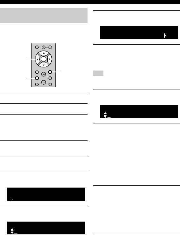
Using the WPS push button configuration
You can easily set up a wireless connection with one push of the WPS button.
Note
This configuration does not work if the security method of your wireless router (access point) is WEP. In this case, use other connection method.
MEMORY
 PRESET
Cursor keys B/ C |
ENTER |
ENTER |
|
HOME |
RETURN |
|
RETURN |
SETUP |
OPTION |
SETUP |
VOLUME |
NOW PLAYING |
MUTE |
Connecting to network
3Use the cursor keys (B / C) to select
“Network” and press ENTER.
y
To return to the previous state, press RETURN.
4Use the cursor keys (B / C) to select
“Connection” and press ENTER.
5Use the cursor keys (B / C) to select
“Wireless” and press ENTER.
WIRELESS


 WPS
WPS
6Press ENTER twice.
“Connecting” appears on the front display.
7Push the WPS button on the wireless router
(access point).
When the connection process finishes, “Completed” appears on the front display. When the setting finishes, verify whether the unit is connected to a wireless network (p. 20).
If “Not connected” appears, repeat from Step 1 or try another connection method.
8To exit from the menu, press SETUP.
About WPS
WPS (Wi-Fi Protected Setup) is a standard established by the Wi-Fi Alliance, which allows easy establishment of a wireless home network.
PREPARATION
1Press A to turn on this unit.
2Press SETUP.
English
17 En
Connecting to network
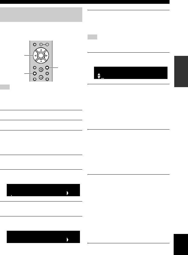
Set the wireless network connection manually
Before performing the following procedure, check the security method and security key on the wireless router (access point).
MEMORY
 PRESET
Cursor keys |
ENTER |
B/ C/ D / E |
|
ENTER |
|
HOME |
RETURN |
|
RETURN |
SETUP |
OPTION |
SETUP |
VOLUME |
NOW PLAYING |
MUTE |
9Use the cursor keys (B / C) to select
“Security” and press ENTER.
SECURITY


 WPA2-PSK(AES)
10Use the cursor keys (D / E) to select desired security method and press RETURN.
Settings
None, WEP, WPA2-PSK (AES), Mixed Mode
Note
If you select “None”, the connection may be insecure since the communication is not encrypted.
1Press A to turn on this unit.
2Press SETUP.
3Use the cursor keys (B / C) to select
“Network ” and press ENTER.
y
To return to the previous state, press RETURN.
4Use the cursor keys (B / C) to select
“Connection” and press ENTER.
5Use the cursor keys (B / C) to select
“Wireless” and press ENTER.
6Use the cursor keys (B/ C) to select “Manual
Setting” and press ENTER.
MANUAL


 SSID
SSID
7Use the cursor keys (B / C) to select “SSID” and press ENTER.
SSID
8Use the cursor keys to enter the SSID on the wireless router (access point), and press
RETURN to previous state.
Use the cursor keys (D/E) to move the edit position and the cursor keys (B/C) to select a character.
11Use the cursor keys (B / C) to select
“Security Key” and press ENTER.
KEY
12Use the cursor keys to enter the security key on the wireless router (access point), and
press RETURN to previous state.
If you select “WEP” in step 10, enter either 5 to 13 character string or 10 to 26 hexadecimal digits.
If you select “WPA2-PSK (AES)” or “Mixed Mode” in step 10, enter either 8 to 63 character string or 64 hexadecimal digits.
Use the cursor keys (D/E) to move the edit position and the cursor keys (B/C) to select a character. You can insert / delete a character, by pressing PRESET i(insert) or PRESET j(delete).
13Use the cursor keys (B / C) to select
“Connect[ENTER]” and press ENTER to save
the setting.
If “ERROR” appears, check the SSID and security key on the wireless router (access point) and repeat from Step 7.
If “ERROR” not appears, a connection is success. Verify whether the unit is connected to a wireless network (p. 20).
14To exit from the menu, press SETUP.
18 En
Connecting a mobile device to the unit directly (Wireless Direct)
Using Wireless Direct, this unit can operate as a wireless network access point that mobile devices can directly connect to.
MEMORY
 PRESET
Cursor keys |
ENTER |
B/ C / D / E |
|
ENTER |
|
HOME |
RETURN |
|
RETURN |
SETUP |
OPTION |
SETUP |
VOLUME |
NOW PLAYING |
MUTE |
Note
When the unit is connected to the network with Wireless Direct, it cannot connect to any other wireless router (access point). To play back contents from the Internet, connect this unit to a network with a wired router or wireless router (access point).
1Press A to turn on this unit.
2Press SETUP.
3Use the cursor keys (B / C) to select
“Network” and press ENTER.
y
To return to the previous state, press RETURN.
4Use the cursor keys (B / C) to select
“Connection” and press ENTER.
5Use the cursor keys (B / C) to select
“WirelesDirect” and press ENTER.
W  DIRECT


 SSID
SSID
6Press ENTER to check the SSID on this unit, and press RETURN to previous state.
7Use the cursor keys (B / C) to select
“Security” and press ENTER.
W  DIRECT


 WPA2-PSK(AES)
Connecting to network
8Use the cursor keys (D / E) to select desired security method and press RETURN.
Settings
None, WPA2-PSK (AES)
Note
If you select “None”, the connection may be insecure since the communication is not encrypted.
9Use the cursor keys (B / C) to select
“Security Key” and press ENTER.
KEY
10Use the cursor keys to enter the security key on this unit, and press RETURN to previous
state.
Enter either 8 to 63 character string or 64 hexadecimal digits.
Use the cursor keys (D/ E) to move the edit position and the cursor keys (B / C) to select a character. You can insert / delete a character, by pressing PRESET i(insert) or PRESET j(delete).
11Use the cursor keys (B / C) to select
“Connect[Enter]” and press ENTER to save
the setting.
The SSID and security key information is required for setup of a mobile device.
When you select the “SSID” in step 6, you can check the configured SSID on this unit. The SSID of this unit can be change by using cursor keys (B/ C / D/ E).
12Configure the Wi-Fi settings of a mobile
device.
For details on settings of your mobile device, refer to the instruction manual of the mobile device.
(1)Enable the Wi-Fi function on the mobile device.
(2)Select the SSID of this unit from the list of available access points.
(3)When you are prompted for a password, enter the security key displayed in Step 10.
If “ERROR” appears, check the security key on this unit and repeat Step 12.
If “ERROR” not appears, a connection is success. Verify whether the unit is connected to a wireless network (p. 20).
13 To exit from the menu, press SETUP.
PREPARATION
English
19 En
Connecting to network
Verify the network connection status
Perform the following procedure to verify the unit’s connection to a network.
MEMORY
 PRESET
Cursor keys B/ C |
ENTER |
ENTER |
|
HOME |
RETURN |
|
RETURN |
SETUP |
OPTION |
SETUP 

VOLUME
NOW PLAYING |
MUTE |
1Press SETUP.
2Use the cursor keys (B / C) to select
“Network” and press ENTER.
y
To return to the previous state, press RETURN.
3Use the cursor keys (B / C) to select
“Information” and press ENTER.
4Use the cursor keys (B / C) to select
“STATUS”.
STATUS


 Connect
When “Connect” appears, the unit is connected to a network. If “Disconnect” appears, reset connection.
5 To exit from the menu, press SETUP.
20 En
Playback
Playing a source
A (power)
PURE DIRECT
VOLUME
|
|
INPUT |
BASS |
TREBLE |
BALANCE |
LOUDNESS |
SELECT |
PHONES |
SPEAKERS |
|
|
|
FLAT |
|
|
|
|
|
|
|
|
|
-30dB |
|
A |
B |
|
|
|
|
|
|
|
|
|
L |
|
R |
|
SPEAKERS A/B |
|
|
|
VOLUME control |
|
INPUT selector |
|
||
SPEAKERS A/B |
SPEAKERS |
|
A (power) |
|
A |
B |
|
||
|
|
|
|
|
|
PHONO |
|
SLEEP |
|
|
COAX 1 |
COAX 2 |
BLUETOOTH |
|
|
OPT 1 |
OPT 2 |
CD |
Input selection |
|
|
|
|
|
|
LINE 1 |
LINE 2 |
LINE 3 |
keys |
|
TUNER |
NET |
USB |
|
SETUP |
OPTION |
VOLUME  VOLUME
NOW PLAYING |
MUTE |
1Press A (power) to turn on this unit.
2Rotate the INPUT selector on the front panel (or press one of the input selection keys on the remote control) to select the input source you want to listen to.
3Press SPEAKERS A and/or SPEAKERS B on the front panel or on the remote control to
select speakers A and/or speakers B.
When speaker set A or speaker set B are turned on, “A” or “B” is displayed on the front display accordingly (p. 7).
Notes
•When one set of speakers is connected using bi-wire connections, or when using two sets of speakers simultaneously (A and B), make sure “A” and “B” are displayed on the front display.
•When listening with headphones, turn off the speakers.
4Play the source.
5Rotate the VOLUME control on the front panel (or press VOLUME +/– on the remote control) to adjust the sound output level.
y
You can adjust the tonal quality by using the BASS, TREBLE, BALANCE and LOUDNESS controls or the PURE DIRECT switch on the front panel.
6When you finish using, press A (Power) on
the front panel to turn off the power.
When you press A(Power) on the remote control, this unit set to standby mode.
■ Enjoying pure high fidelity sound
(Pure Direct)
When the PURE DIRECT switch is turned on, routes input signals from your audio sources so that the input signals bypass the BASS, TREBLE, BALANCE and LOUDNESS controls, thus eliminating any alterations to the audio signals and creating the purest possible sound. The PURE DIRECT indicator lights up and the front display turns off after a few seconds.
PURE DIRECT switch
PURE DIRECT
VOLUME
|
|
INPUT |
BASS |
TREBLE |
BALANCE |
LOUDNESS |
SELECT |
PHONES |
SPEAKERS |
|
|
|
FLAT |
|
|
|
|
|
|
|
|
|
-30dB |
|
A |
B |
|
|
|
|
|
|
|
|
|
L |
|
R |
|
Notes
•When the PURE DIRECT switch is turned on, the front display turns off.
•The BASS, TREBLE, BALANCE, and LOUDNESS controls do not function while the PURE DIRECT switch is turned on.
OPERATION |
BASIC |
|
|
English
21 En
Playback
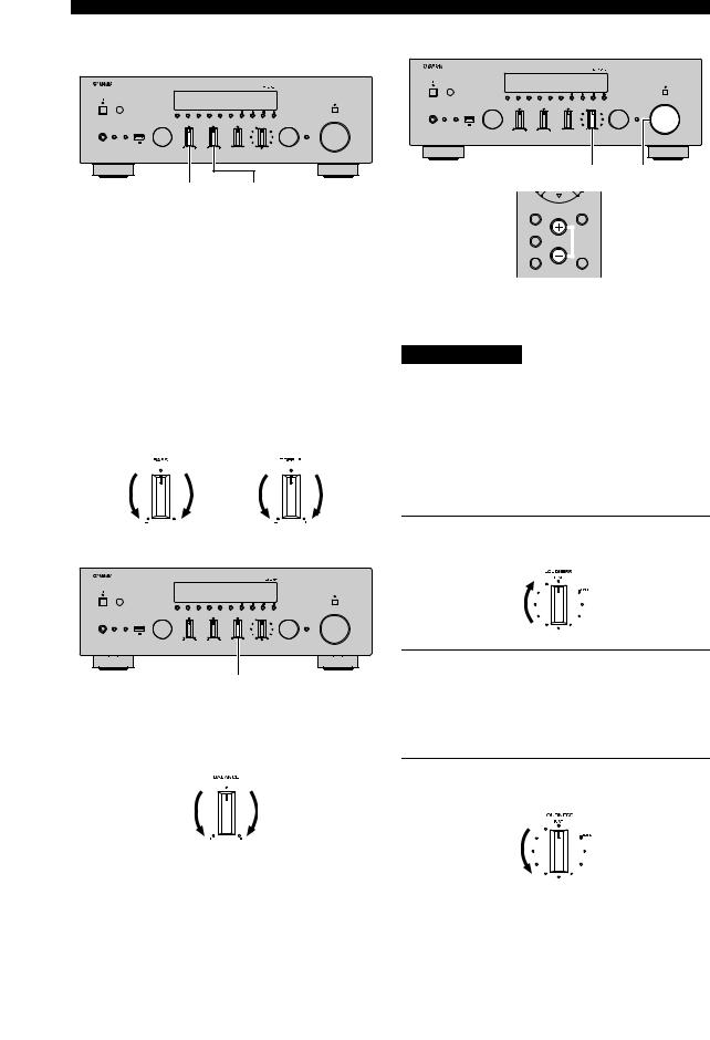
■Adjusting the BASS and TREBLE controls
PURE DIRECT
VOLUME
|
|
INPUT |
BASS |
TREBLE |
BALANCE |
LOUDNESS |
SELECT |
PHONES |
SPEAKERS |
|
|
|
FLAT |
|
|
|
|
|
|
|
|
|
-30dB |
|
A |
B |
|
|
|
|
|
|
|
|
|
L |
|
R |
|
BASS TREBLE
The BASS and TREBLE controls adjust high and low frequency response.
The center position produces a flat response.
BASS control
When you feel there is not enough bass (low frequency sound), rotate clockwise to boost. When you feel there is too much bass, rotate counterclockwise to suppress. Control range: –10 dB to +10 dB (20 Hz)
TREBLE control
When you feel there is not enough treble (high frequency sound), rotate clockwise to boost. When you feel there is too much treble, rotate counterclockwise to suppress.
Control range: –10 dB to +10 dB (20 kHz)
■ Adjusting the BALANCE control
PURE DIRECT
VOLUME
|
|
INPUT |
BASS |
TREBLE |
BALANCE |
LOUDNESS |
SELECT |
PHONES |
SPEAKERS |
|
|
|
FLAT |
|
|
|
|
|
|
|
|
|
-30dB |
|
A |
B |
|
|
|
|
|
|
|
|
|
L |
|
R |
|
BALANCE
The BALANCE control adjusts the sound output balance of the left and right speakers to compensate for sound imbalance caused by speaker locations or listening room conditions.
■ Adjusting the LOUDNESS control
PURE DIRECT
VOLUME
|
|
INPUT |
BASS |
TREBLE |
BALANCE |
LOUDNESS |
SELECT |
PHONES |
SPEAKERS |
|
|
|
FLAT |
|
|
|
|
|
|
|
|
|
-30dB |
|
A |
B |
|
|
|
|
|
|
|
|
|
L |
|
R |
|
LOUDNESS VOLUME
HOME |
RETURN |
SETUP |
OPTION |
VOLUME  VOLUME +/–
NOW PLAYING |
MUTE |
Retain a full tonal range at any volume level, thus compensating for the human ears’ loss of sensitivity to high and low-frequency ranges at low volume.
CAUTION
If the PURE DIRECT switch is turned on with the LOUDNESS control set at a certain level, the input signals bypass the LOUDNESS control, resulting in a sudden increase in the sound output level. To prevent your ears or the speakers from being damaged, be sure to press the PURE DIRECT switch after lowering the sound output level or after checking that the LOUDNESS control is properly set.
1Set the LOUDNESS control to the FLAT position.
2Rotate the VOLUME control on the front panel (or press VOLUME +/– on the remote control) to set the sound output level to the loudest listening level that you would listen to.
3Rotate the LOUDNESS control until the desired volume is obtained.
y
After setting the LOUDNESS control, enjoy listening to music at your preferred volume level. If the effect of the LOUDNESS control setting is too strong or weak, readjust the LOUDNESS control.
22 En
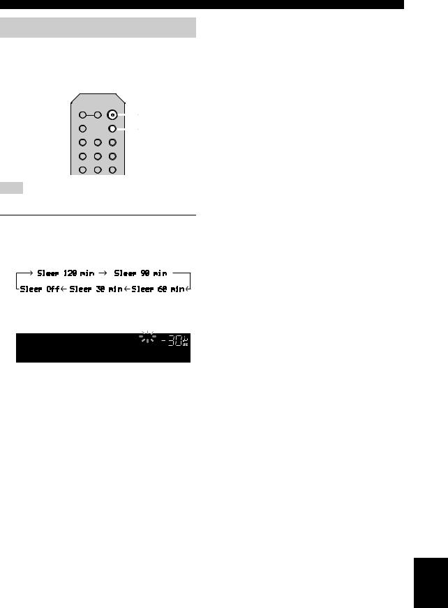
Using the sleep timer
Use this feature to automatically set this unit to standby mode after a certain amount of time. The sleep timer is useful when you are going to sleep while this unit is playing or recording a source.
SPEAKERS
A |
B |
A (power) |
PHONO |
|
SLEEP |
|
|
SLEEP |
COAX 1 |
COAX 2 |
BLUETOOTH |
OPT 1 |
OPT 2 |
CD |
LINE 1 |
LINE 2 |
LINE 3 |
Note
The sleep timer can only be set with the remote control.
1Press SLEEP repeatedly to set the amount of
time before this unit is set to standby mode.
Each time you press SLEEP, the front display changes as shown below.
The SLEEP indicator blinks while setting the amount of time for the sleep timer.
SLEEP
A VOL.
Sleep 120min.
If the sleep timer is set, the SLEEP indicator on the front display lights up.
y
•To disable the sleep timer, select “Sleep Off”.
•The sleep timer setting can also be canceled by pressing A (power) to set this unit to standby mode.
Playback
OPERATION |
BASIC |
|
|
English
23 En
Listening to FM/AM radio
FM/AM tuning
SPEAKERS |
|
A |
B |
PHONO |
SLEEP |
COAX 1 COAX 2 BLUETOOTH
OPT 1 |
OPT 2 |
CD |
|
|
LINE 1 |
LINE 2 |
LINE 3 |
|
|
TUNER |
NET |
USB |
|
|
TUNER |
|
|
|
|
BAND |
TUNING |
TUNING jj / ii |
||
BAND |
||||
|
|
|||
MEMORY |
PRESET |
|
||
|
|
|||
1Press TUNER to select “TUNER” as the input source.
2Press BAND repeatedly to select the reception band (FM or AM).
3Press and hold TUNING jj / ii for more than
1 second to begin tuning.
Press iito tune in to a higher frequency. Press jjto tune in to a lower frequency.
The frequency of the received station is shown in the front display.
If a broadcast is being received, “TUNED” indicator on the front display will be lit. If a stereo broadcast is being received, the “STEREO” indicator will also lit.
STEREO TUNED
A VOL.
FM 98.5 MHz
Frequency
y
•If the station signals are weak, tuning search does not stop at the desired station.
•When the signal reception for an FM radio station is unstable, switching to monaural may improve it.
■ Improving FM reception (FM mode)
If the signal from the station is weak and the sound quality is not good, set the FM band reception mode to monaural mode to improve reception.
PURE DIRECT
VOLUME
|
|
INPUT |
BASS |
TREBLE |
BALANCE |
LOUDNESS |
SELECT |
PHONES |
SPEAKERS |
|
|
|
FLAT |
|
|
|
|
|
|
|
|
|
-30dB |
|
A |
B |
|
|
|
|
|
|
|
|
|
L |
|
R |
|
MODE
1Press MODE repeatedly to select “Stereo” (automatic stereo mode) or “Mono” (monaural mode) when this unit is tuned in to
an FM radio station.
When Mono is selected, FM broadcasts will be heard in monaural sound.
Note
The STEREO indicator on the front panel lights up while listening to a station in stereo mode.
Automatic preset tuning (FM stations only)
You can use the automatic preset tuning function to automatically register FM stations as presets. This function enables this unit to automatically tune in to FM stations that have a strong signal and register up to 40 of those stations in order. You can then easily recall any preset station by selecting its preset number.
Notes
•If a station is registered to a preset number that already has a station registered to it, the previously registered station is overwritten.
•If the station you want to register is weak in signal strength, try using the manual preset tuning method.
y
FM stations registered as presets using the automatic preset registration feature will be heard in stereo.
24 En
LINE 1 |
LINE 2 |
LINE 3 |
|
TUNER |
NET |
USB |
|
TUNER |
|
|
|
BAND |
TUNING |
|
|
BAND |
|
||
|
|
|
|
MEMORY |
PRESET |
PRESET j / i |
|
|
|||
|
|
|
|
Cursor keys B/ C |
ENTER |
|
|
ENTER |
|
|
|
HOME |
|
RETURN |
RETURN |
|
|
|
|
SETUP |
|
OPTION |
OPTION |
|
VOLUME |
|
|
NOW PLAYING |
|
MUTE |
|
1Press TUNER to select “TUNER” as the input source.
2Press OPTION on the remote control.
The “Option” menu is displayed (p. 42).
3Press B / C to select “Auto Preset”, and then press ENTER.
OPTION |
|
A |
VOL. |
|
Auto Preset |
|
|||
|
|
|
|
|
READY |
|
A |
VOL. |
|
01:FM 87.5 MHz |
||||
|
|
|
|
|
Preset number |
Frequency |
|
||
This unit starts scanning the FM band about 5 seconds later from the lowest frequency upwards. To begin scanning immediately, hold down ENTER.
y
•Before scanning begins, you can specify the first preset number to be used by pressing PRESET j/ ior cursor key (B/C) on the remote control.
•To cancel scanning, press BAND or RETURN.
Listening to FM/AM radio
Manual tuning preset
Select a radio station manually and register it to a preset number. You can then easily recall any preset station by selecting its preset number.
TUNER NET USB
|
BAND |
TUNING |
|
|
|
|
|
MEMORY |
MEMORY |
PRESET |
PRESET j / i |
|
|||
|
|
ENTER
1Follow “FM/AM tuning” (p.24) to tune into the desired radio station.
2Hold down MEMORY for more than 2 seconds.
The first time that you do register a station, the selected radio station will be registered to the preset number “01”. Thereafter, each radio station you select will be registered to the next empty (unused) preset number after the most recently registered number.
MEMORY |
STEREO TUNED |
|
A |
VOL. |
01:FM 98.5 MHz
Preset number
y
To select a preset number for registering, press MEMORY once after tuning into the desired radio station, press PRESET j/ i to select a preset number, and then press MEMORY again.
985 |
STEREO TUNED |
|
A |
VOL. |
02:Empty
“Empty” (not in use) or the frequency currently registered
OPERATION |
BASIC |
|
|
When scanning is complete, “FINISH” is displayed and then the display returns to original state.
English
25 En
Loading...