


 Loading...
YAMAHA PZ50X, PZ50GTX, PZ50RTX, PZ50MTX, PZ50VTX SERVICE MANUAL
...SUPPLEMENTARY SERVICE MANUAL 2008
PZ50X
PZ50GTX
PZ50RTX
PZ50MTX
PZ50VTX
PZ50MPX
LIT-12618-02-67 |
8GC-28197-11 |
FOREWORD
This Supplementary Service Manual has been prepared to introduce new service and new data for the PZ50X, PZ50GTX, PZ50RTX, PZ50MTX, PZ50VTX, PZ50MPX. For complete information, on service procedures, it is necessary to use this Supplementary Service Manual together with following manual:
PZ50W, PZ50GTW, PZ50FXW, PZ50MW, PZ50VTW, PZ50MPW SERVICE MANUAL: 8GC-28197-10 (LIT-12618-02-58)
PZ50X, PZ50GTX, PZ50RTX, PZ50MTX,
PZ50VTX, PZ50MPX
SUPPLEMENTARY SERVICE MANUAL ©2007 by Yamaha Motor Corporation, U.S.A.
1st Edition, November 2007
All rights reserved. Any reprinting or unauthorized use without the written permission of Yamaha Motor Corporation, U.S.A. is expressly prohibited.
Printed in U.S.A.
P/N.LIT-12618-02-67

NOTICE
This manual was written by the Yamaha Motor Company primarily for use by Yamaha dealers and their qualified mechanics. It is not possible to put an entire mechanic’s education into one manual, so it is assumed that persons using this book to perform maintenance and repairs on Yamaha snowmobiles have a basic understanding of the mechanical concepts and procedures inherent in snowmobile repair. Without such knowledge, attempted repairs or service to this model may render it unfit and/or unsafe to use.
This model has been designed and manufactured to perform within certain specifications in regard to performance and emissions. Proper service with the correct tools is necessary to ensure that the vehicle will operate as designed. If there is any question about a service procedure, it is imperative that you contact a Yamaha dealer for any service information changes that apply to this model. This policy is intended to provide the customer with the most satisfaction from his vehicle and to conform to federal environmental quality objectives.
Yamaha Motor Company, Ltd. is continually striving to improve all models manufactured by Yamaha. Modifications and significant changes in specifications or procedures will be forwarded to all authorized Yamaha dealers and will, where applicable, appear in future editions of this manual.
HOW TO USE THIS MANUAL
Particularly important information is distinguished in this manual by the following notations:
The Safety Alert Symbol means ATTENTION! BE ALERT! YOUR SAFETY IS INVOLVED!
 WARNING Failure to follow WARNING instructions could result in severe injury or death to the snowmobile operator, a bystander, or a person inspecting or repairing the snowmobile.
CAUTION: A CAUTION indicates special precautions that must be taken to avoid damage to the snowmobile.
NOTE: A NOTE provides key information that can make procedures easier or clearer.
MANUAL FORMAT
All of the procedures in this manual are organized in a sequential, step-by-step format. The information has been compiled to provide the mechanic with an easy to read, handy reference that contains comprehensive explanations of all inspection, repair, assembly, and disassembly operations.
In this revised format, the condition of a faulty component will precede an arrow symbol and the course of action required to correct the problem will follow the symbol, e.g.,
•Bearings
Pitting/damage → Replace.
EXPLODED DIAGRAM
Each chapter provides exploded diagrams before each disassembly section to facilitate correct disassembly and assembly procedures.
1 |
|
2 |
|
|
|
GEN |
|
|
INSP |
|
|
INFO |
|
|
ADJ |
|
|
3 |
|
4 |
|
|
|
CHAS |
|
|
POWR |
|
|
|
|
TR |
|
|
|
|
|
|
|
|
|
5 |
|
6 |
|
|
|
ENG |
|
|
COOL |
|
|
7 |
|
8 |
|
|
|
FI |
|
|
ELEC |
– |
+ |
9 |
|
|
|
|
|
SPEC |
|
|
|
|
|
0 |
A |
|
B |
|
|
|
|
|
|
T |
|
|
|
|
|
. |
|
|
|
|
|
R |
|
|
|
|
|
. |
|
C |
D |
|
E |
|
|
F |
G |
|
H |
|
|
|
|
LT |
|
5 |
|
I |
J |
K |
L |
|
|
E |
G |
|
M |
BF |
|
M |
N |
|
O |
|
|
B |
|
LS |
|
M |
|
P |
Q |
|
R |
|
|
S |
|
|
New |
|
|
ILLUSTRATED SYMBOLS (Refer to the illustration)
Illustrated symbols 1 to 9 are designed as thumb tabs to indicate the chapter’s number and content.
1General information
2Periodic inspection and adjustment
3Chassis
4Power train
5Engine
6Cooling system
7Fuel injection system
8Electrical
9Specifications
Illustrated symbols 0 to F are used to identify the specifications which appear.
0 Filling fluid
ALubricant
BTightening torque
CWear limit, clearance
DEngine speed
ESpecial tool
FElectrical data (Ω, V, A)
Illustrated symbols G to R in the exploded diagram indicate grade of lubricant and location of lubrication point.
GApply locking agent (LOCTITE®)
HApply Yamabond No.5®
IApply engine oil
JApply gear oil
KApply molybdenum disulfide oil
LApply brake fluid
MApply wheel bearing grease
NApply low-temperature lithium-soap-based grease
OApply molybdenum disulfide grease
PApply silicone grease
QESSO beacon 325 grease or Aeroshell grease #7A
RUse new one
INDEX
GENERAL INFORMATION |
GEN |
1 |
|
INFO |
PERIODIC INSPECTION AND ADJUSTMENT
INSPADJ |
2 |
CHASSIS
CHAS 3
POWER TRAIN |
|
|
|
|
|
|
|
|
|
|
|
POWR |
4 |
||||
|
TR |
||||
|
|
|
|
|
|
|
|
|
|
|
|
|
|
|
|
|
|
|
|
|
|
|
|
|
|
|
|
|
|
|
|
|
|
|
|
ENGINE
ENG 5
COOLING SYSTEM
COOL 6
FUEL INJECTION SYSTEM |
7 |
FI |
– |
+ |
ELECTRICAL |
8 |
ELEC |
SPECIFICATIONS
SPEC 9

PERIODIC INSPECTION AND |
|
ADJUSTMENT |
|
TUNING ................................................................ |
1 |
FRONT SUSPENSION ................................... |
1 |
AIR PRESSURE ADJUSTMENT (PZ50RT) ... |
3 |
REAR SUSPENSION ..................................... |
5 |
CHASSIS |
|
COWLINGS ........................................................ |
10 |
PZ50/PZ50GT/PZ50RT/PZ50MT.................. |
10 |
STEERING.......................................................... |
12 |
PZ50/PZ50GT/PZ50RT/PZ50MT.................. |
12 |
FRONT SUSPENSION ....................................... |
15 |
PZ50/PZ50RT/PZ50MT ................................ |
15 |
PZ50GT/PZ50VT/PZ50MP ........................... |
17 |
INSTALLATION ............................................ |
19 |
POWER TRAIN |
|
SLIDE RAIL SUSPENSION................................ |
20 |
PZ50/PZ50GT/PZ50RT/PZ50MT.................. |
20 |
PZ50VT/PZ50MP.......................................... |
24 |
ENGINE |
|
SEAT AND FUEL TANK .................................... |
29 |
PZ50/PZ50GT/PZ50RT/PZ50MT.................. |
29 |
BALANCER ........................................................ |
31 |
REMOVAL .................................................... |
33 |
INSTALLATION ............................................ |
33 |
FUEL INJECTION SYSTEM |
|
THROTTLE BODY.............................................. |
35 |
INJECTORS.................................................. |
35 |
SPECIFICATIONS |
|
GENERAL SPECIFICATIONS ........................... |
37 |
MAINTENANCE SPECIFICATIONS .................. |
41 |
ENGINE ........................................................ |
41 |
POWER TRAIN............................................. |
46 |
CHASSIS ..................................................... |
52 |
ELECTRICAL ............................................... |
54 |
TIGHTENING TORQUE..................................... |
57 |
ENGINE ....................................................... |
57 |
POWER TRAIN............................................ |
59 |
CHASSIS ..................................................... |
61 |
GENERAL TORQUE SPECIFICATIONS .......... |
63 |
DEFINITION OF UNITS ..................................... |
63 |
CABLE ROUTING ............................................. |
64 |
|
|
FRONT SUSPENSION |
INSP |
|
||
|
|
ADJ |
|
|||
È |
|
PERIODIC INSPECTION AND |
||||
|
|
|
|
ADJUSTMENT |
|
|
|
|
TUNING |
|
|
|
|
|
|
FRONT SUSPENSION |
|
|
||
|
|
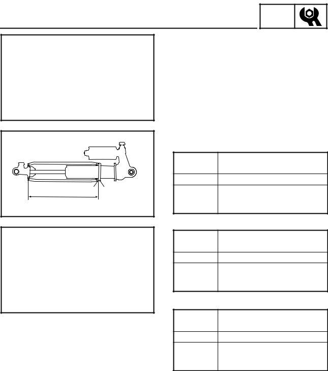
Spring preload |
|
|
||
|
|
1. Adjust: |
|
|
|
|
|
|
|
• Spring preload |
|
|
|
|
|
Adjustment steps: |
|
|
||
É |
|
• |
Loosen the locknut 1. |
|
|
|
|
• |
Turn the spring seat 2 in or out. |
|
|||
|
|
|
||||
|
|
PZ50GT |
|
|
|
|
|
|
Spring seat |
|
Standard |
|
|
|
|
distance |
Shorter ← |
|
→ Longer |
|
|
|
Preload |
Harder ← |
|
→ Softer |
|
|
|
2 1 |
|
Min. |
|
Max. |
|
a |
Length a |
172 mm |
182 mm |
182 mm |
|
|
|
|
(6.77 in) |
(7.17 in) |
(7.17 in) |
|
|
|
|
|
|||
Ê |
|
PZ50MT “Europe” |
|
|
||
|
Spring seat |
|
Standard |
|
||
|
|
|
|
|||
|
|
distance |
Shorter ← |
|
→ Longer |
|
|
|
Preload |
Harder ← |
|
→ Softer |
|
|
|
|
|
Min. |
|
Max. |
|
|
Length a |
215 mm |
225 mm |
226 mm |
|
|
|
|
|
(8.46 in) |
(8.86 in) |
(8.90 in) |
|
|
PZ50VT “Europe”/PZ50MP |
|
|||
|
|
Spring seat |
|
Standard |
|
|
|
|
distance |
Shorter ← |
|
→ Longer |
|
|
|
Preload |
Harder ← |
|
→ Softer |
|
|
|
|
|
Min. |
|
Max. |
|
|
Length a |
205 mm |
215 mm |
216 mm |
|
|
|
|
|
(8.07 in) |
(8.46 in) |
(8.50 in) |
• Turn the adjusting ring 3 to the proper position.
PZ50/PZ50MT “USA/Canada”/PZ50VT “USA/
Canada”
Spring adjuster |
1 |
2 |
3 |
4 |
5 |
|
position |
||||||
|
|
|
|
|
||
|
|
|
|
|
|
|
Preload |
Softer ← |
|
→ Harder |
|||
|
|
|
|
|
|
|
Standard |
|
|
1 |
|
|
|
|
|
|
|
|
|
|
È PZ50MT “Europe”/PZ50VT “Europe”/PZ50MP
É PZ50GT
Ê PZ50/PZ50MT “USA/Canada”/PZ50VT “USA/Can-
ada”
1
FRONT SUSPENSION
CAUTION:
INSP ADJ
Be sure that the left and right spring preload are the same.
 WARNING
These shock absorber contain highly pressurized nitrogen gas.
Do not tamper with or attempt to open the shock absorber assemblies.
Do not subject the shock absorber assemblies to flames or high heat, which could cause it to explode.
b |
|
1 |
a |
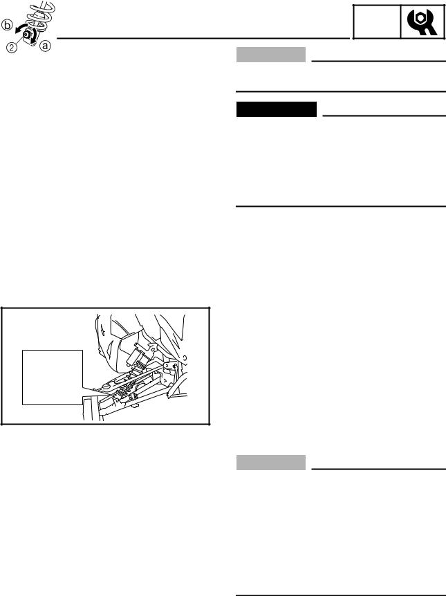
Rebound damping force adjustment (PZ50GT)
The rebound damping force can be adjusted by turning the adjuster 1.
|
20 clicks out |
12 clicks out |
3 clicks out |
||||||
Adjuster |
|
|
|
|
|
|
|
|
|
|
|
|
|
|
|
|
|
|
|
position |
Minimum |
Standard |
Maximum |
||||||
|
Turns out b* ← → Turns in a |
||||||||
|
|
|
|
|
|
|
|
|
|
Rebound |
|
|
|
|
|
|
|
|
|
damping |
Soft ← |
|
|
|
→ Hard |
||||
force |
|
|
|
|
|
|
|
|
|
|
|
|
|
|
|
|
|
|
|
* With the adjuster fully turned lightly in direction a
CAUTION:
•Do not continue to turn the adjuster in direction a after it stops. The shock absorber can be damaged and rebound damping force adjustments cannot be made.
•Do not turn the adjuster in direction b more than 20 clicks. Even if the adjuster is continually turned after 20 clicks, there will be no change in the rebound damping force.
•Be sure to stop the adjuster at a position where there is a click.
2
FRONT SUSPENSION/ AIR PRESSURE ADJUSTMENT (PZ50RT)
INSP ADJ
b |
|
1 |
a |
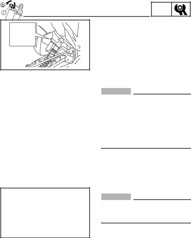
Compression damping force adjustment (PZ50GT)
The compression damping force can be adjusted by turning the adjuster 1.
|
12 clicks out |
7 clicks out |
2 clicks out |
||||||
Adjuster |
|
|
|
|
|
|
|
|
|
|
|
|
|
|
|
|
|
|
|
position |
Minimum |
Standard |
Maximum |
||||||
|
Turns out b* ← → Turns in a |
||||||||
|
|
|
|
|
|
|
|
|
|
Compres- |
|
|
|
|
|
|
|
|
|
sion damp- |
Soft ← |
|
|
|
→ Hard |
||||
ing force |
|
|
|
|
|
|
|
|
|
|
|
|
|
|
|
|
|
|
|
* With the adjuster fully turned lightly in direction a
CAUTION:
•Do not continue to turn the adjuster in direction a after it stops. The shock absorber can be damaged and compression damping force adjustments cannot be made.
•Do not turn the adjuster in direction b more than 12 clicks. Even if the adjuster is continually turned after 12 clicks, there will be no change in the compression damping force.
•Be sure to stop the adjuster at a position where there is a click.
AIR PRESSURE ADJUSTMENT (PZ50RT)
CAUTION:
The left and right shock absorber air pressure must be set to the same setting. Uneven settings can cause poor handling and loss of stability.
This snowmobile is equipped with FOX shock absorbers as standard equipment.
The air pressure of the shock absorbers can be adjusted using the shock absorber pump 1 included with your snowmobile.
3

AIR PRESSURE ADJUSTMENT (PZ50RT)
Adjustment steps:
INSP ADJ
 WARNING
Support the snowmobile securely on a suitable stand before adjusting the shock absorbers.
CAUTION:
Make sure that there is no load on the shock absorbers and that they are fully extended before making any air pressure adjustments.
1.Place the snowmobile on a level surface and apply the parking brake.
2.Lift the front of the snowmobile onto a suitable stand to raise the skis off the ground.
3.Remove the air valve cap 1 from the shock absorber.
4.Install the hose connector 2 of the shock absorber pump onto the air valve of the shock absorber and tighten it approximately six turns until the pressure registers on the pump gauge.
CAUTION:
Do not overtighten the connector onto the air valve as this will damage the connector seal.
NOTE:
If the shock absorber has no air pressure, the gauge reading will be zero.
5.To increase the air pressure, operate the pump a few times. The pressure should increase slowly. If the pressure increases rapidly, check to make sure that the pump is properly connected and tightened onto the air valve. To decrease the air pressure, push the black bleed valve button 3.
NOTE:
To allow pressure to escape from the pump and the shock absorber, push the button halfway down and hold it. To allow only a small amount of pressure to escape, push the button all the way down and quickly release it.
4
AIR PRESSURE ADJUSTMENT (PZ50RT)/ REAR SUSPENSION
INSP ADJ
6. Remove the hose connector from the air valve.
NOTE:
When removing the connector, the sound of air escaping may be heard, but this is from the pump hose, not the shock absorber.
Air pressure range:
345 kPa (3.4 kgf/cm², 50 psi) to 1,034 kPa (10.3 kgf/cm², 150 psi)
Recommended air pressure: 483 kPa (4.8 kgf/cm², 70 psi)
CAUTION:
Do not exceed 1,034 kPa (10.3 kgf/cm², 150 psi).
7. Install the air valve cap.
NOTE:
If the front suspension bottoms too easily or rolls too much during cornering, increase the air pressure by 34 kPa (0.3 kgf/cm², 5 psi). If the suspension is too firm and you want a more compliant ride, decrease the air pressure by 34 kPa (0.3 kgf/cm², 5 psi).
REAR SUSPENSION
Stopper band
1.Adjust:
• Stopper band length
CAUTION:
Make sure the left and right rear suspension stopper bands are adjusted evenly. (PZ50VT, PZ50MP)
NOTE:
This adjustment affects the handling characteristics of the machine.
5
INSP
REAR SUSPENSION ADJ
È |
1 |
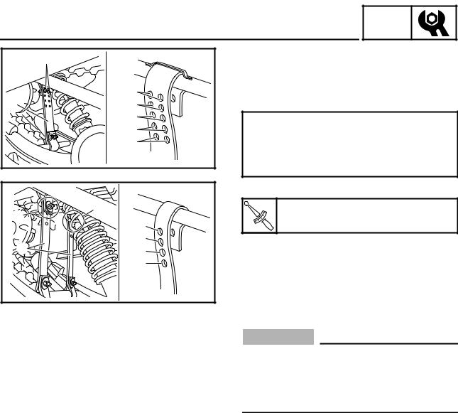
Adjustment steps: |
||
|
• Remove the stopper band bolts 1, nuts and |
|||
|
|
|||
|
|
washers. |
||
|
No.1 |
• Adjust the length of the stopper bands 2 by |
||
2 |
No.2 |
inserting the bolts in different holes. |
||
|
No.3 |
Standard setting: |
||
|
No.4 |
No. 1 hole (PZ50/PZ50VT “Europe”/PZ50MP) |
||
|
No.5 |
No. 2 holes (PZ50GT/PZ50RT) |
||
|
|
No. 3 holes (PZ50MT) |
||
|
|
No. 4 hole (PZ50VT “USA/Canada”) |
||
ÈÉ |
|
• Tighten the stopper band nuts. |
||
1 |
1 |
|
Stopper band nut: |
|
No.1 |
|
4 Nm (0.4 m · kg, 2.9 ft · lb) |
||
|
. |
|||
|
. |
|
||
|
|
T |
|
|
|
|
R |
|
|
|
No.2 |
È PZ50/PZ50GT/PZ50RT/PZ50MT |
||
2 |
No.3 |
|||
É PZ50VT/PZ50MP |
||||
|
No.4 |
|
|
|
Choosing other settings:
CAUTION:
The standard settings work well under most general riding conditions. The suspension can be adjusted to work better in one condition, but only at the expense of another. Keep this in mind when you adjust the suspension.
|
È: No. 5 hole |
|
No. 1 hole |
|
É: No. 4 hole |
|
|
|
|
(longest) |
|
|
(shortest) |
|
|
|
|
|
|
|
|
||
More weight on skis: |
Less weight on skis: |
||
• |
Heavy steering/ |
• |
Light steering/ |
|
oversteer |
|
understeer |
• |
More maneuverabil- |
• |
Better acceleration |
|
ity |
|
and speed |
Favors: hardpack |
Favors: deep snow, |
||
snow, ice, smooth |
straight line accelera- |
||
trails, tight turns |
tion, top speed |
||
|
|
|
|
È PZ50/PZ50GT/PZ50RT/PZ50MT É PZ50VT/PZ50MP
6

|
|
|
|
|
|
|
|
|
|
REAR SUSPENSION |
|
INSP |
|
|
|
|
|
|
ADJ |
|
|
||
|
Spring preload |
||||||
|
È |
||||||
|
|
1. Adjust: |
|||||
|
|
|
• Spring preload |
||||
|
|
Adjustment step: |
|||||
|
|
Front side |
|||||
|
|
• |
Loosen the locknut 1. |
||||
|
|
• |
Turn the spring seat 2 in or out. |
||||
PZ50GT “Europe”/PZ50RT “USA/Canada”/
PZ50MT “Europe”
Spring seat |
|
Standard |
|
distance |
Shorter ← |
|
→ Longer |
|
|
|
|
Preload |
Harder ← |
|
→ Softer |
|
|
|
|
|
Min. |
|
Max. |
Length a |
180 mm |
190 mm |
191 mm |
|
(7.09 in) |
(7.48 in) |
(7.52 in) |
|
|
|
|
PZ50RT “Europe” |
|
|
|
|
|
|
|
Spring seat |
|
Standard |
|
distance |
Shorter ← |
|
→ Longer |
|
|
|
|
Preload |
Harder ← |
|
→ Softer |
|
|
|
|
|
Min. |
|
Max. |
Length a |
178 mm |
188 mm |
189 mm |
|
(7.01 in) |
(7.40 in) |
(7.44 in) |
|
|
|
|
PZ50VT “Europe”/PZ50MP |
|
||
|
|
|
|
Spring seat |
|
Standard |
|
distance |
Shorter ← |
|
→ Longer |
|
|
|
|
Preload |
Harder ← |
|
→ Softer |
|
|
|
|
|
Min. |
|
Max. |
Length a |
194 mm |
204 mm |
205 mm |
|
(7.64 in) |
(8.03 in) |
(8.07 in) |
|
|
|
|
È PZ50GT “Europe”/PZ50RT/PZ50MT “Europe”/
PZ50VT “Europe”/PZ50MP
7
|
|
|
|
|
|
|
|
|
|
|
|
|
|
|
|
|
REAR SUSPENSION |
|
INSP |
|
|
|
|
||||||||
|
|
|
ADJ |
|
|
|
|
||||||||
|
|
• Turn the adjusting ring 3 to the proper position. |
|||||||||||||
É |
|
||||||||||||||
|
|
PZ50/PZ50GT “USA/Canada”/PZ50MT “USA/ |
|||||||||||||
|
|
Canada”/PZ50VT “USA/Canada” |
|
|
|
|
|||||||||
|
|
|
|
|
|
|
|
|
|
|
|
|
|
|
|
|
|
Spring adjuster |
|
1 |
|
|
2 |
|
3 |
|
4 |
|
5 |
||
|
|
position |
|
|
|
|
|
|
|||||||
|
|
|
|
|
|
|
|
|
|
|
|
|
|
|
|
|
|
|
|
|
|
|
|
|
|
|
|
||||
|
|
Preload |
|
Softer ← |
|
|
|
→ Harder |
|||||||
|
|
|
|
|
|
|
|
|
|
|
|
|
|
|
|
|
|
Standard |
|
|
|
|
|
|
1 |
|
|
|
|
|
|
|
|
|
|
|
|
|
|
|
|
|
|
|
|
|
|
|
|
|
|
|
|
|
|
|
|
|
|
|
|
|
|
|
|
WARNING |
|
|
|
|
|
|
|
|
|
|
|
|
|
|
|
|
|
|
|
|
|
|
|
|
|
|
|
|
|
|
|
This shock absorber contains highly pressur- |
|||||||||||||
|
|
ized nitrogen gas. |
|
|
|
|
|
|
|
|
|
|
|
|
|
|
|
Do not tamper with or attempt to open the |
|||||||||||||
|
|
shock absorber assembly. |
|
|
|
|
|
|
|
|
|||||
|
|
Do not subject the shock absorber assembly to |
|||||||||||||
|
|
flames or high heat, which could cause it to |
|||||||||||||
|
|
explode. |
|
|
|
|
|
|
|
|
|
|
|
|
|
|
|
|
|
|
|
|
|
|
|
||||||
|
|
É PZ50/PZ50GT “USA/Canada”/PZ50MT “USA/Can- |
|||||||||||||
|
|
ada”/PZ50VT “USA/Canada” |
|
|
|
|
|
|
|
||||||
|
|
Rear side |
|
|
|
|
|
|
|
|
|
|
|
|
|
|
|
|
|
|
|
|
|
|
|
|
|
|
|
|
|
|
|
• Turn the adjuster 1 to proper position. |
|
|
|||||||||||
|
|
|
|
|
|
|
|
|
|
|
|
|
|
|
|
|
|
Spring adjuster |
|
|
S |
|
|
M |
|
|
|
H |
|||
|
|
position |
|
|
|
|
|
|
|
||||||
|
|
|
|
|
|
|
|
|
|
|
|
|
|
|
|
|
|
|
|
|
|
|
|
|
|
|
|||||
|
|
Spring rate |
|
|
Soft |
|
Medium |
|
|
Hard |
|||||
|
|
|
|
|
|
|
|
|
|
|
|
|
|
|
|
|
|
Standard |
|
|
|
|
|
|
|
M |
|
|
|
|
|
|
|
|
|
|
|
|
|
|
|
|
|
|
|
|
|
|
|
|
|
|
|
|
|
|
|
|
|
|
|
|
|
|
|
WARNING |
|
|
|
|
|
|
|
|
|
|
|
|
|
|
|
Always adjust both spring preload (left and |
|||||||||||||
|
|
right) to the same setting. Uneven adjustment |
|||||||||||||
|
|
can cause poor handling and loss of stability. |
|||||||||||||
|
|
|
|
|
|
|
|
|
|
|
|
|
|
|
|
8

INSP
REAR SUSPENSION ADJ
Rear suspension damping force adjustment
The damping force can be adjusted by turning the adjuster 1.
PZ50RT
|
20 clicks out |
11 clicks out |
1 click out |
||||||
Adjuster |
|
|
|
|
|
|
|
|
|
|
|
|
|
|
|
|
|
|
|
position |
Minimum |
Standard |
Maximum |
||||||
|
Turns out b* ← → Turns in a |
||||||||
|
|
|
|
|
|
|
|
|
|
Damping |
Soft ← |
|
|
|
→ Hard |
||||
force |
|
|
|
||||||
|
|
|
|
|
|
|
|
|
|
|
|
|
|
|
|
|
|
|
|
* With the adjuster fully turned lightly in direction a
CAUTION:
•Do not continue to turn the adjuster in direction a after it stops. The shock absorber can be damaged and damping force adjustments cannot be made.
•Do not turn the adjuster in direction b more than 20 clicks. Even if the adjuster is continually turned after 20 clicks, there will be no change in the damping force.
•Be sure to stop the adjuster at a position where there is a click.
9

COWLINGS CHAS 


|
|
|
CHASSIS |
|
|
|
COWLINGS |
|
|
|
|
|
|
PZ50/PZ50GT/PZ50RT/PZ50MT |
|
|
|
|
|
|
È: 8 Nm (0.8 m • kg, 5.8 ft • lb) |
|
|
|
4 |
PZ50RT |
|
|
|
|
|
|
||
12 |
|
|
|
|
|
|
È |
|
|
|
|
1 |
|
2 |
6 |
|
|
|
5 |
È |
|
|
|
|
|
||
3 |
|
|
|
11 |
|
|
|
|
|
|
|
|
|
18 |
|
|
16 |
15 |
|
|
19 |
|
|
|
|
|
|
|
|
|
13 |
|
7 |
|
|
|
|
|
|
||
|
19 |
17 |
|
14 |
|
|
|
|
|
|
|
||
|
|
|
|
|
|
|
|
|
|
|
20 |
|
|
8 |
|
|
|
|
|
|
È |
|
|
|
|
9 |
|
10 |
|
|
|
|
|
È |
Order |
Job name/Part name |
Q’ty |
Remarks |
|
|
|
|
|
Cowling removal |
|
Remove the parts in the order listed below. |
1 |
Windshield |
1 |
PZ50GT |
2 |
Front panel |
1 |
|
3 |
Air filter case cover |
1 |
|
4 |
Headlight cover |
1 |
|
5 |
Left side panel |
1 |
|
6 |
Right side panel |
1 |
|
7 |
Left side cover |
1 |
|
8 |
Right side cover |
1 |
|
9 |
Left lower cover |
1 |
|
10 |
Right lower cover |
1 |
|
11 |
Headlight coupler |
2 |
|
12 |
Headlight assembly |
1 |
|
13 |
Cylinder-#2 intake air pressure sensor cou- |
1 |
Disconnect. |
|
pler |
|
|
|
|
|
|
10

COWLINGS CHAS 


È: 8 Nm (0.8 m • kg, 5.8 ft • lb) |
|
|
|
4 |
PZ50RT |
|
|
|
|
|
|
||
12 |
|
|
|
|
|
|
È |
|
|
|
|
1 |
|
2 |
6 |
|
|
|
5 |
È |
|
|
|
|
|
||
3 |
|
|
|
11 |
|
|
|
|
|
|
|
|
|
18 |
|
|
16 |
15 |
|
|
19 |
|
|
|
|
|
|
|
|
|
13 |
|
7 |
|
|
|
|
|
|
||
|
19 |
17 |
|
14 |
|
|
|
|
|
|
|
||
|
|
|
|
|
|
|
|
|
|
|
20 |
|
|
8 |
|
|
|
|
|
|
È |
|
|
|
|
9 |
|
10 |
|
|
|
|
|
È |
Order |
Job name/Part name |
Q’ty |
Remarks |
|
|
|
|
14 |
Cylinder-#1 intake air pressure sensor cou- |
1 |
Disconnect. |
|
pler |
|
|
15 |
Intake air temperature sensor coupler |
1 |
Disconnect. |
16 |
Cylinder head breather hose |
1 |
Disconnect. |
17 |
Oil tank breather hose |
1 |
Disconnect. |
18 |
Air filter case assembly |
1 |
|
19 |
Air filter case assembly pad (left and right) |
2 |
|
20 |
Intake air pressure sensor hose |
2 |
|
|
|
|
For installation, reverse the removal proce- |
|
|
|
dure. |
|
|
|
|
11
STEERING CHAS 


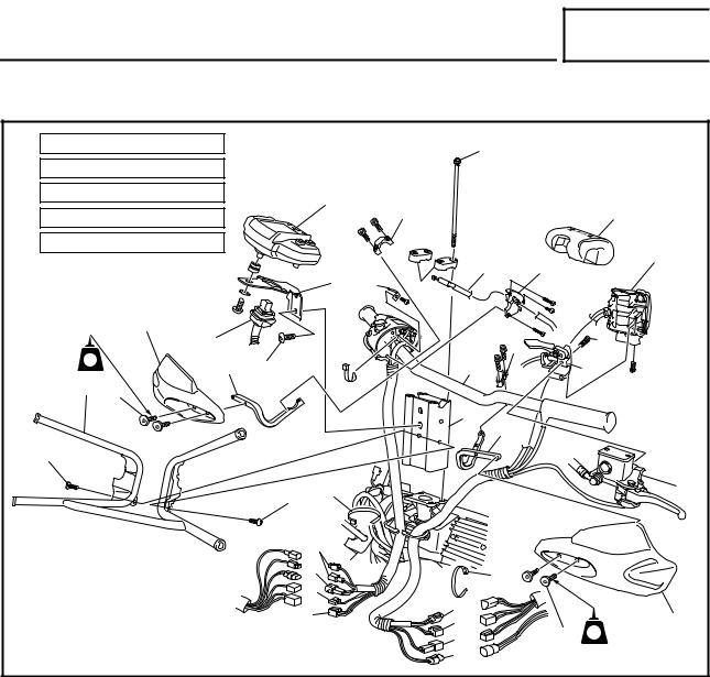
STEERING |
|
|
|
|
|
|
|
PZ50/PZ50GT/PZ50RT/PZ50MT |
|
|
|
|
|
||
È: 7 Nm (0.7 m • kg, 5.1 ft • lb) |
|
|
|
Ê |
|
||
É: 10 Nm (1.0 m • kg, 7.2 ft • lb) |
|
|
|
|
|
||
Ê: |
15 Nm (1.5 m • kg, 11 ft • lb) |
|
6 |
|
3 |
8 |
|
|
|
|
|
|
|||
Ë: |
16 Nm (1.6 m • kg, 11 ft • lb) |
|
|
|
|||
|
|
|
|
|
|||
Ì: |
20 Nm (2.0 m • kg, 14 ft • lb) |
|
|
|
|
20 |
|
|
|
|
|
|
|
19 |
|
|
|
|
|
7 |
|
17 |
|
|
|
|
|
18 |
|
||
|
|
|
|
23 |
|
||
|
|
2 |
|
|
|
|
|
|
|
5 |
|
|
|
3 |
É |
|
|
|
|
|
|
||
|
LT |
4 |
Ì |
|
|
24 |
21 |
|
1 |
|
|
||||
|
È |
|
|
|
|
|
|
|
|
|
|
|
|
25 |
|
|
|
|
|
|
|
4 |
|
Ë |
|
|
|
|
|
|
|
|
|
|
Ë |
9 |
|
|
22 |
|
|
|
|
|
|
||
|
|
|
|
12 |
|
|
|
|
|
|
|
11 |
|
9 |
|
|
|
|
|
10 |
|
|
|
|
|
|
|
|
|
|
|
|
|
|
13 |
|
14 |
2 |
|
|
|
|
|
13 |
|||
|
|
|
|
|
|
15 |
È LT |
|
|
|
|
|
|
16 |
|
Order |
Job name/Part name |
Q’ty |
Remarks |
|
|
|
|
|
Handlebar removal |
|
Remove the parts in the order listed below. |
|
Windshield/left side panel/right side panel |
|
Refer to “COWLINGS”. |
1 |
Windshield bracket |
1 |
PZ50GT/PZ50RT/PZ50MT |
2 |
Wind deflector (left and right) |
2 |
PZ50RT |
3 |
Wind deflector bracket holder |
2 |
PZ50RT |
4 |
Wind deflector bracket |
2 |
PZ50RT |
5 |
Multi-function meter coupler |
1 |
|
6 |
Multi-function meter |
1 |
|
7 |
Multi-function meter bracket |
1 |
|
8 |
Steering pad |
1 |
PZ50GT/PZ50RT/PZ50MT |
9 |
Plastic band |
2 |
|
10 |
Thumb warmer lead coupler |
1 |
Disconnect. |
11 |
Engine stop switch coupler |
1 |
Disconnect. |
12 |
Throttle switch coupler |
2 |
Disconnect. |
13 |
Grip warmer lead connector |
2 |
Disconnect. |
14 |
Grip thumb warmer adjustment switch lead |
1 |
Disconnect. |
|
coupler |
|
|
|
|
|
|
12

STEERING CHAS 


È: 7 Nm (0.7 m • kg, 5.1 ft • lb) |
|
|
|
Ê |
|
||
É: 10 Nm (1.0 m • kg, 7.2 ft • lb) |
|
|
|
|
|
||
Ê: |
15 Nm (1.5 m • kg, 11 ft • lb) |
|
6 |
|
3 |
8 |
|
|
|
|
|
|
|||
Ë: |
16 Nm (1.6 m • kg, 11 ft • lb) |
|
|
|
|||
|
|
|
|
|
|||
Ì: |
20 Nm (2.0 m • kg, 14 ft • lb) |
|
|
|
|
20 |
|
|
|
|
|
|
|
19 |
|
|
|
|
|
7 |
|
17 |
|
|
|
|
|
18 |
|
||
|
|
|
|
23 |
|
||
|
|
2 |
|
|
|
|
|
|
|
5 |
|
|
|
3 |
É |
|
|
|
|
|
|
||
|
LT |
4 |
Ì |
|
|
24 |
21 |
|
1 |
|
|
||||
|
È |
|
|
|
|
|
|
|
|
|
|
|
|
25 |
|
|
|
|
|
|
|
4 |
|
Ë |
|
|
|
|
|
|
|
|
|
|
Ë |
9 |
|
|
22 |
|
|
|
|
|
|
||
|
|
|
|
12 |
|
|
|
|
|
|
|
11 |
|
9 |
|
|
|
|
|
10 |
|
|
|
|
|
|
|
|
|
|
|
|
|
|
13 |
|
14 |
2 |
|
|
|
|
|
13 |
|||
|
|
|
|
|
|
15 |
È LT |
|
|
|
|
|
|
16 |
|
Order |
Job name/Part name |
Q’ty |
|
|
Remarks |
|
|
|
|
|
|
||
15 |
Brake light switch coupler |
1 |
Disconnect. |
|
||
16 |
Headlight beam switch coupler |
1 |
|
Disconnect. |
|
|
17 |
Right handlebar switch cover |
1 |
|
|
|
|
18 |
Throttle cable holder |
1 |
|
|
|
|
19 |
Throttle cable |
1 |
|
|
|
|
20 |
Left handlebar switch |
1 |
|
|
|
|
21 |
Brake master cylinder holder |
1 |
|
|
|
|
22 |
Master cylinder assembly |
1 |
|
NOTE: |
|
|
23 |
Handlebar holder |
2 |
|
After installing all parts, refer to “CABLE |
|
|
24 |
Handlebar |
1 |
|
ROUTING”, to check the cable and lead rout- |
|
|
25 |
Steering joint |
1 |
|
ings. |
|
|
|
|
|
|
|
|
|
|
|
|
|
For installation, reverse the removal proce- |
|
|
|
|
|
|
dure. |
|
|
|
|
|
|
|
|
|
13
|
STEERING |
CHAS |
|
|
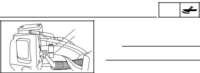
1. Install: |
|
|
1 |
For PZ50RT |
|
|
2 |
• Wind deflector bracket holder 1 |
||
• Wind deflector bracket 2 |
|||
|
|||
|
NOTE: |
|
|
|
Align the end of the wind deflector bracket with the |
||
|
punch mark a on the handlebar. |
||
a |
|
|
|
14
FRONT SUSPENSION CHAS 
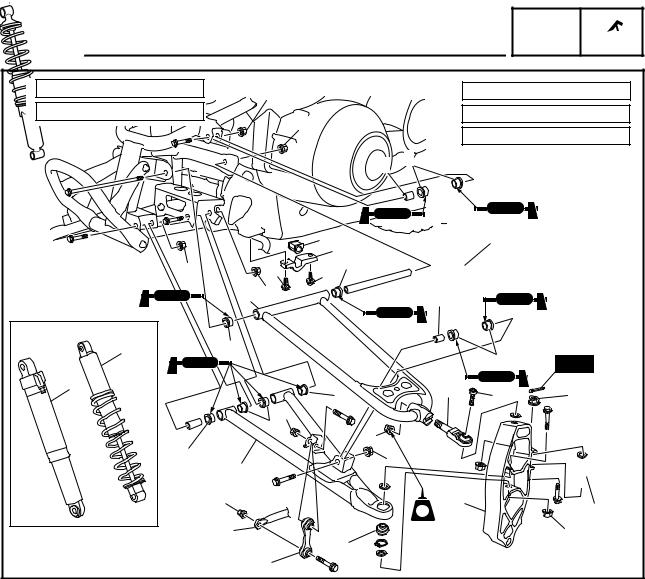
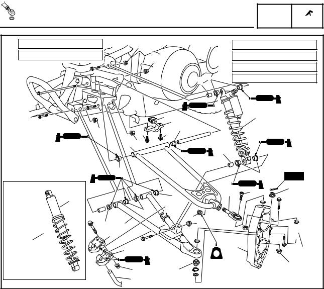
FRONT SUSPENSION
PZ50/PZ50RT/PZ50MT |
|
|
|
|
|
|
|
È: 28 Nm (2.8 m • kg, 20 ft • lb) |
Ê |
|
|
Ê: 45 Nm (4.5 m • kg, 32 ft • lb) |
|||
É: |
34 Nm (3.4 m • kg, 24 ft • lb) |
|
Ê |
|
Ë: |
90 Nm (9.0 m • kg, 65 ft • lb) |
|
|
|
|
|
Ì: 65 Nm (6.5 m • kg, 47 ft • lb) |
|||
|
|
|
|
|
|||
|
|
|
|
4 |
5 |
|
|
|
|
|
|
|
|
|
|
|
|
|
12 |
|
|
1 |
|
|
|
|
11 |
|
|
|
|
|
Ì |
É |
É 10 |
|
|
|
|
|
|
9 Ì |
|
|
4 |
|
|
|
3 |
10 |
|
|
|
5 |
New |
|
|
|
|
|
|
||
|
2 |
|
16 |
|
8 |
Ê |
È |
|
|
|
|
||||
|
|
|
|
|
|||
|
|
É |
|
|
|
|
|
|
|
16 |
|
Ë |
|
|
|
|
|
|
|
|
|
|
|
|
16 |
15 |
|
Ê |
|
|
|
|
|
|
|
|
|
|
|
|
|
Ê |
|
|
7 |
|
6 |
|
|
|
|
|
LT |
|
|
|
|
14 |
17 |
|
|
|
Ì |
|
|
|
|
|
|
||
|
|
|
|
|
|
|
|
|
|
13 |
|
|
|
|
|
Order |
Job name/Part name |
Q’ty |
Remarks |
|
|
|
|
|
Front suspension removal |
|
Remove the parts in the order listed below. |
|
Air filter case cover |
|
Refer to “COWLINGS”. |
|
Pivot arm cover |
|
Refer to “STEERING”. |
|
Ski |
|
Refer to “SKI” in CHAPTER 3. |
1 |
Shock absorber |
1 |
PZ50/PZ50MT “USA/Canada” |
2 |
Shock absorber |
1 |
PZ50RT |
3 |
Shock absorber |
1 |
PZ50MT “Europe” |
4 |
Collar |
2 |
PZ50/PZ50MT |
5 |
Bushing |
4 |
PZ50/PZ50MT |
6 |
Tie rod |
1 |
Disconnect. |
7 |
Steering knuckle |
1 |
|
8 |
Upper arm ball joint |
1 |
|
9 |
Upper arm |
1 |
|
10 |
Bushing |
2 |
|
11 |
Stabilizer holder |
1 |
|
12 |
Bushing |
1 |
|
|
|
|
|
15
FRONT SUSPENSION CHAS 
È: 28 Nm (2.8 m • kg, 20 ft • lb) |
Ê |
|
|
Ê: 45 Nm (4.5 m • kg, 32 ft • lb) |
|||
É: |
34 Nm (3.4 m • kg, 24 ft • lb) |
|
Ê |
|
Ë: |
90 Nm (9.0 m • kg, 65 ft • lb) |
|
|
|
|
|
Ì: 65 Nm (6.5 m • kg, 47 ft • lb) |
|||
|
|
|
|
|
|||
|
|
|
|
4 |
5 |
|
|
|
|
|
|
|
|
|
|
|
|
|
12 |
|
|
1 |
|
|
|
|
11 |
|
|
|
|
|
Ì |
É |
É 10 |
|
|
|
|
|
|
9 Ì |
|
|
4 |
|
|
|
3 |
10 |
|
|
|
5 |
New |
|
|
|
|
|
|
||
|
2 |
|
16 |
|
8 |
Ê |
È |
|
|
|
|
||||
|
|
|
|
|
|||
|
|
É |
|
|
|
|
|
|
|
16 |
|
Ë |
|
|
|
|
|
|
|
|
|
|
|
|
16 |
15 |
|
Ê |
|
|
|
|
|
|
|
|
|
|
|
|
|
Ê |
|
|
7 |
|
6 |
|
|
|
|
|
LT |
|
|
|
|
14 |
17 |
|
|
|
Ì |
|
|
|
|
|
|
||
|
|
|
|
|
|
|
|
|
|
13 |
|
|
|
|
|
Order |
Job name/Part name |
Q’ty |
Remarks |
|
|
|
|
13 |
Stabilizer joint |
1 |
|
14 |
Stabilizer |
1 |
|
15 |
Lower arm |
1 |
|
16 |
Bushing |
4 |
|
17 |
Lower arm ball joint |
1 |
|
|
|
|
For installation, reverse the removal proce- |
|
|
|
dure. |
|
|
|
|
16
FRONT SUSPENSION CHAS 
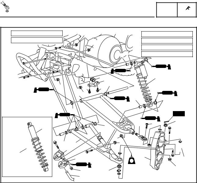
PZ50GT/PZ50VT/PZ50MP |
|
|
|
|
|
|
|
È: 7 Nm (0.7 m • kg, 5.1 ft • lb) |
Ë |
|
|
Ê: |
34 Nm (3.4 m • kg, 24 ft • lb) |
||
É: |
28 Nm (2.8 m • kg, 20 ft • lb) |
|
Ë |
|
Ë: |
45 Nm (4.5 m • kg, 32 ft • lb) |
|
|
|
|
|
Ì: 90 Nm (9.0 m • kg, 65 ft • lb) |
|||
|
|
|
|
|
|||
|
|
|
4 |
5 |
Í: |
65 Nm (6.5 m • kg, 47 ft • lb) |
|
|
|
|
1211 |
|
|
1 |
|
|
Í |
Ê |
Ê 10 |
|
|
|
|
|
|
9 Í |
|
|
4 |
|
|
|
|
|
|
|
|
|
|
|
|
10 |
|
|
|
5 |
New |
|
|
|
|
|
|
||
|
|
|
16 |
|
8 |
Ë |
É |
|
3 |
|
|
|
|||
|
|
|
|
|
|
||
|
|
|
|
|
|
|
|
|
|
16 |
Ì |
|
|
|
|
|
|
|
|
|
|
|
|
|
16 |
15 |
Ë |
|
|
|
|
|
|
|
|
|
|
||
|
2 |
13 |
|
|
|
|
|
|
|
13 |
|
|
|
7 |
6 |
|
|
|
|
LT |
|
||
|
|
|
|
|
|
|
|
|
|
|
|
|
|
|
Í |
|
|
È |
17 |
|
|
|
|
|
|
14 |
|
|
|
|
|
Order |
Job name/Part name |
Q’ty |
Remarks |
|
|
|
|
|
Front suspension removal |
|
Remove the parts in the order listed below. |
|
Air filter case cover |
|
Refer to “COWLINGS”. |
|
Pivot arm cover |
|
Refer to “STEERING”. |
|
Ski |
|
Refer to “SKI” in CHAPTER 3. |
1 |
Shock absorber |
1 |
PZ50GT |
2 |
Shock absorber |
1 |
PZ50VT “USA/Canada” |
3 |
Shock absorber |
1 |
PZ50VT “Europe”/PZ50MP |
4 |
Collar |
2 |
|
5 |
Bushing |
4 |
|
6 |
Tie rod |
1 |
Disconnect. |
7 |
Steering knuckle |
1 |
|
8 |
Upper arm ball joint |
1 |
|
9 |
Upper arm |
1 |
|
10 |
Bushing |
2 |
|
11 |
Stabilizer holder |
1 |
|
12 |
Bushing |
1 |
|
|
|
|
|
17
FRONT SUSPENSION CHAS 
È: 7 Nm (0.7 m • kg, 5.1 ft • lb) |
Ë |
|
|
Ê: |
34 Nm (3.4 m • kg, 24 ft • lb) |
||
É: |
28 Nm (2.8 m • kg, 20 ft • lb) |
|
Ë |
|
Ë: |
45 Nm (4.5 m • kg, 32 ft • lb) |
|
|
|
|
|
Ì: 90 Nm (9.0 m • kg, 65 ft • lb) |
|||
|
|
|
|
|
|||
|
|
|
4 |
5 |
Í: |
65 Nm (6.5 m • kg, 47 ft • lb) |
|
|
|
|
1211 |
|
|
1 |
|
|
Í |
Ê |
Ê 10 |
|
|
|
|
|
|
9 Í |
|
|
4 |
|
|
|
|
|
|
|
|
|
|
|
|
10 |
|
|
|
5 |
New |
|
|
|
|
|
|
||
|
|
|
16 |
|
8 |
Ë |
É |
|
3 |
|
|
|
|||
|
|
|
|
|
|
||
|
|
|
|
|
|
|
|
|
|
16 |
Ì |
|
|
|
|
|
|
|
|
|
|
|
|
|
16 |
15 |
Ë |
|
|
|
|
|
|
|
|
|
|
||
|
2 |
13 |
|
|
|
|
|
|
|
13 |
|
|
|
7 |
6 |
|
|
|
|
LT |
|
||
|
|
|
|
|
|
|
|
|
|
|
|
|
|
|
Í |
|
|
È |
17 |
|
|
|
|
|
|
14 |
|
|
|
|
|
Order |
Job name/Part name |
Q’ty |
Remarks |
|
|
|
|
13 |
Stabilizer bracket |
2 |
|
14 |
Stabilizer |
1 |
|
15 |
Lower arm |
1 |
|
16 |
Bushing |
4 |
|
17 |
Lower arm ball joint |
1 |
|
|
|
|
For installation, reverse the removal proce- |
|
|
|
dure. |
|
|
|
|
18
FRONT SUSPENSION CHAS 
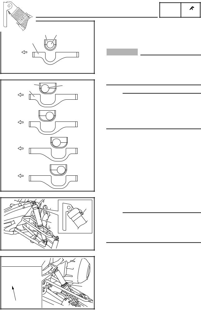
È
2 1
3
a
É |
2 |
1 |
|
||
|
3 |
|
|
a |
b |
|
|
a |
c |
|
a |
d |
|
a |
e |
|
INSTALLATION
1.Install:
•Stabilizer 1
•Bushing 2
•Stabilizer holder 3
CAUTION:
Always install the stabilizers, bushings, and stabilizer holders in the same positions on both sides of the snowmobile, otherwise poor handling and loss of stability may result. (PZ50GT/ PZ50VT/PZ50MP)
NOTE:
•Install the stabilizer holder in the direction shown in the illustration. (PZ50/PZ50RT/PZ50MT)
•The stabilizer force can be adjusted by changing the installation positions of the stabilizer, bushing, and stabilizer holder. (PZ50GT/PZ50VT/ PZ50MP)
ÈPZ50/PZ50RT/PZ50MT
É PZ50GT/PZ50VT/PZ50MP
aForward
bVery hard
cHard
dMedium
eSoft
Stabilizer, bushing, and stabilizer holder standard installation positions:
d (PZ50GT)
b (PZ50VT/PZ50MP)
a |
1 |
1 |
b |
2.Install:
• Shock absorber 1
NOTE:
•Install the shock absorber with the air valve a facing outward. (PZ50RT)
•Install the shock absorber with the charging valve b facing inward. (PZ50MT “Europe”/PZ50VT “Europe”/PZ50MP)
19
POWR
SLIDE RAIL SUSPENSION TR
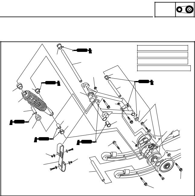
POWER TRAIN
SLIDE RAIL SUSPENSION
PZ50/PZ50GT/PZ50RT/PZ50MT |
|
|
|
|
|
|
|
|
|
|
È: 4 Nm (0.4 m • |
kg, 2.9 ft • lb) |
|
8 |
|
|
|
É: 49 Nm (4.9 m • kg, 35 ft • lb) |
|
|
|
9 |
|
|
Ê: 60 Nm (6.0 m • kg, 43 ft • lb) |
|
|
|
|
|
|
Ë: 110 Nm (11.0 m • kg, 80 ft • |
lb) |
|
|
|
É |
0 |
|
|
|
|
|
|
|
|
|
|
5 |
|
|
A |
|
|
|
7 |
|
|
|
|
|
|
3 |
|
|
|
|
|
|
2 |
|
|
Ë |
|
|
|
4 |
|
|
|
0 |
|
|
|
|
|
|
|
|
|
6 |
|
|
8 |
Ê |
|
|
|
5 |
|
|
|
|
|
|
|
|
|
|
|
|
3 |
|
|
|
|
|
|
|
|
|
|
É |
|
|
|
|
|
Ê |
|
|
|
È |
|
|
|
|
|
|
|
È |
|
|
|
|
|
1 |
|
|
|
|
|
|
|
B |
|
|
|
|
|
|
|
|
|
|
Ê |
|
|
|
|
|
Ê |
|
|
Order |
Job name/Part name |
Q’ty |
Remarks |
|
|
|
|
|
Slide rail suspension disassembly |
|
Remove the parts in the order listed below. |
1 |
Stopper band |
1 |
|
2 |
Front shock absorber |
1 |
|
3 |
Bushing |
2 |
|
4 |
Collar |
1 |
|
5 |
Bushing |
2 |
|
6 |
Collar |
1 |
|
7 |
Front pivot arm |
1 |
|
8 |
Bushing |
2 |
|
9 |
Shaft |
1 |
|
0 |
Collar |
2 |
|
A |
Shaft |
1 |
|
B |
Shaft |
1 |
|
|
|
|
|
20
|
SLIDE RAIL SUSPENSION |
POWR |
||
|
TR |
|||
|
È |
È: |
6 Nm (0.6 m • kg, 4.3 ft • lb) |
|
|
G |
|||
|
|
|
|
|
|
H |
É: 60 Nm (6.0 m • kg, 43 ft • lb) |
||
É |
|
Ê: |
72 Nm (7.2 m • kg, 52 ft • lb) |
|
|
|
|
|
|
|
|
J |
O |
|
|
|
Ê |
|
|
C |
E |
|
|
|
|
|
|
||
I |
|
|
|
|
New D |
|
|
|
|
|
|
|
|
|
|
|
K |
|
P |
|
|
|
|
|
|
F |
|
|
H |
|
|
|
|
|
|
É |
I |
|
È |
Ê |
|
|
|
|
|
|
|
G |
|
|
|
|
|
|
LT |
|
|
|
|
|
|
|
F |
|
N É |
|
|
|
|
M |
L |
|
|
D New |
|
L M |
|
|
C |
|
N |
|
E |
|
|
|
|
||
|
|
|
|
|
|
É |
|
|
|
PZ50MT |
|
É |
|
É |
|
|
|
|
|
|
LT |
Ê |
|
|
Order |
Job name/Part name |
Q’ty |
|
|
Remarks |
|
|
|
|
|
|
|
|
C |
Suspension wheel |
2 |
|
|
|
|
D |
Circlip |
2 |
|
|
|
|
E |
Spring end guide |
2 |
|
NOTE: |
|
|
|
|
|
|
Apply grease to the inner surface of each |
|
|
|
|
|
|
spring end guide. |
|
|
F |
Spring end guide bracket |
2 |
|
|
|
|
|
|
|
|
|||
G |
Wheel bracket |
2 |
|
|
|
|
H |
Suspension wheel |
2 |
|
|
|
|
I |
Bushing |
2 |
|
|
|
|
J |
Shaft |
1 |
|
|
|
|
K |
Front suspension bracket |
1 |
|
|
|
|
L |
Suspension wheel |
2 |
|
|
|
|
M |
Collar |
2 |
|
|
|
|
N |
Wheel bracket |
2 |
|
|
|
|
O |
Connecting arm |
1 |
|
|
|
|
P |
Collar |
2 |
|
|
|
|
|
|
|
|
|
|
|
21
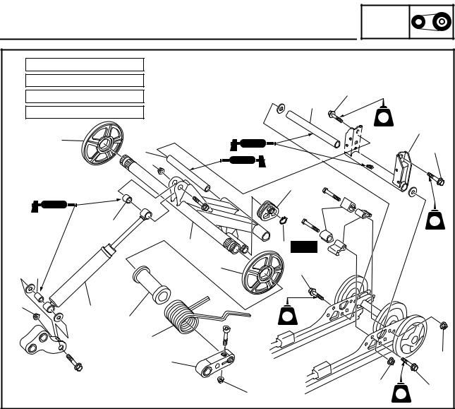
|
|
SLIDE RAIL SUSPENSION |
POWR |
|
|
|
|
TR |
|
||
È: 35 Nm (3.5 m • kg, 25 ft • lb) |
|
|
|
|
|
É: |
49 Nm (4.9 m • kg, 35 ft • lb) |
|
Ë |
|
|
Ê: |
60 Nm (6.0 m • kg, 43 ft • lb) |
|
|
|
|
|
\ |
|
|
||
Ë: |
72 Nm (7.2 m • kg, 52 ft • lb) |
|
|
|
|
|
|
LT |
|
||
|
|
|
|
|
|
|
|
|
|
|
[ |
|
Z |
|
|
|
Ë |
|
Y |
|
|
|
|
|
É |
|
|
|
|
|
|
|
W |
|
|
|
|
|
] |
|
|
|
R |
|
^ |
|
LT |
|
X |
|
V New |
|
|
|
R |
Z |
Ë |
|
|
|
|
|
|
||
|
|
|
|
|
|
É |
Q |
|
|
|
|
|
|
LT |
|
|
|
|
U |
|
|
|
|
|
|
|
|
|
|
|
T |
|
|
|
|
|
S |
|
|
|
Ê |
|
|
|
|
|
|
|
|
|
È |
Ê |
Ë |
|
|
|
LT |
|
|
Order |
Job name/Part name |
Q’ty |
Remarks |
|
|
|
|
Q |
Rear shock absorber |
1 |
|
R |
Collar |
2 |
|
S |
Rear pivot arm joint |
2 |
|
T |
Torsion spring |
2 |
|
U |
Rear pivot arm protector |
2 |
|
V |
Circlip |
2 |
|
W |
Adjuster |
2 |
|
X |
Rear pivot arm |
1 |
|
Y |
Shaft |
1 |
|
Z |
Guide wheel |
2 |
|
[ |
Rear pivot arm bracket |
1 |
|
\ |
Shaft |
1 |
|
] |
Collar |
4 |
|
_ |
Stopper |
4 |
|
|
|
|
|
22
|
|
|
SLIDE RAIL SUSPENSION |
POWR |
|
||
|
|
|
TR |
|
|||
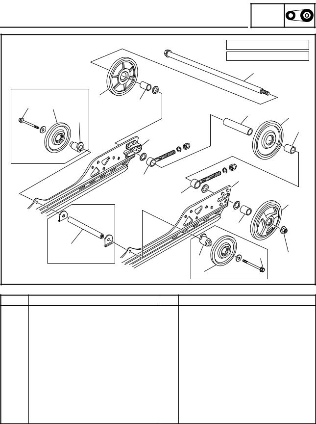
|
|
|
|
È: |
60 Nm (6.0 m • kg, 43 ft • lb) |
||
|
|
|
|
É: 75 Nm (7.5 m • kg, 54 ft • lb) |
|||
|
|
|
|
|
|
a |
|
PZ50MT |
b |
d |
|
|
|
|
|
|
È |
h |
|
|
|
|
|
|
|
|
|
|
|
||
|
|
i |
|
|
|
g |
c |
|
|
|
|
|
|
||
|
|
|
|
|
|
|
|
|
|
|
|
|
|
|
f |
|
|
|
k |
|
|
|
|
|
|
|
e |
|
k |
|
|
|
|
|
|
|
|
|
|
|
|
|
e |
|
|
|
|
|
|
|
|
|
|
|
b |
|
|
|
|
|
d |
|
|
|
|
j |
|
|
|
|
|
|
|
PZ50MT |
i |
|
|
È |
É |
|
|
|
|
|
|
||
|
|
|
h |
PZ50MT |
|
||
Order |
|
Job name/Part name |
Q’ty |
|
Remarks |
|
|
a |
Rear axle |
1 |
|
|
|
|
|
b |
Guide wheel |
2 |
|
|
|
|
|
c |
Guide wheel |
1 |
|
|
|
|
|
d |
Collar |
|
2 |
|
|
|
|
e |
Tension adjuster |
2 |
|
|
|
|
|
f |
Collar |
|
1 |
|
|
|
|
g |
Collar |
|
1 |
|
|
|
|
h |
Suspension wheel |
2 |
|
|
|
|
|
i |
Wheel bracket |
2 |
|
|
|
|
|
j |
Shaft |
|
1 |
|
|
|
|
k |
Sliding frame |
2 |
|
|
|
|
|
For assembly, reverse the disassembly procedure.
23
|
|
|
|
|
|
|
|
|
POWR |
|
|
|
|
|
|
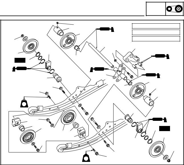
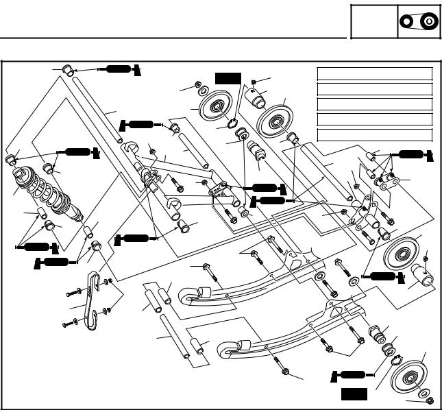
SLIDE RAIL SUSPENSION |
TR |
|
|||||
PZ50VT/PZ50MP |
|
|
|
|
|
|
|
|
|
|
|
6 |
|
|
|
New |
|
É |
|
È: |
4 Nm (0.4 m • kg, 2.9 ft • lb) |
||
|
|
|
|
|
|
||||||
|
|
|
|
|
|
É: |
6 Nm (0.6 m • kg, 4.3 ft • lb) |
||||
|
|
|
Ë |
|
|
A |
B |
||||
|
|
|
|
|
|
|
Ê: |
49 Nm (4.9 m • kg, 35 ft • lb) |
|||
|
7 |
|
|
K |
|
|
|
||||
|
|
|
|
|
|
Ë: |
60 Nm (6.0 m • kg, 43 ft • lb) |
||||
|
|
|
|
L |
|
|
|
||||
|
Ê |
|
|
|
|
|
Ì: |
72 Nm (7.2 m • kg, 52 ft • lb) |
|||
|
8 |
M |
|
D |
|
||||||
I |
|
|
|
|
0 |
|
|||||
|
5 |
|
|
|
|
|
|
||||
|
|
9 |
|
|
|
|
F |
|
|||
I |
|
|
|
|
N |
|
|
|
C Ì |
|
|
|
|
|
|
|
|
|
G |
|
E |
||
|
|
|
|
Ì |
|
|
|
|
|
||
|
|
|
|
|
|
|
|
|
|
|
|
H |
|
|
|
|
|
|
|
|
|
|
|
J |
J |
|
|
6 |
8 |
|
|
Ê |
|
|
|
|
|
|
|
|
D |
|
|||||
I |
|
|
|
|
|
|
|
|
|
||
|
|
|
|
|
|
|
|
|
B |
||
|
|
|
|
|
|
|
|
|
|
|
|
|
|
|
|
Ë |
|
|
|
|
|
|
É |
|
|
|
|
|
|
|
|
|
|
|
|
|
I |
|
|
Ë |
|
|
|
|
|
|
|
|
|
3 |
|
|
|
|
|
|
|
|
|
|
È |
|
|
|
|
|
|
|
|
A |
|
|
|
|
|
|
|
|
|
|
|
|
|
1 |
4 |
|
|
|
|
|
|
|
|
|
|
|
|
|
|
|
|
|
|
|
N |
|
|
|
|
|
|
|
|
|
|
|
|
|
|
|
2 |
|
|
3 |
|
|
|
|
|
M |
|
|
|
|
|
|
|
|
|
|
K |
||
|
|
|
|
|
|
|
|
|
|
|
|
|
|
|
|
|
|
|
|
|
Ë |
|
|
|
|
|
|
|
|
|
|
Ë |
|
|
|
|
|
|
|
|
|
|
|
|
New L |
|
|
|
|
|
|
|
|
|
|
|
|
Ë |
|
Order |
Job name/Part name |
Q’ty |
Remarks |
|
|
|
|
|
Slide rail suspension disassembly |
|
Remove the parts in the order listed below. |
1 |
Stopper band |
2 |
|
2 |
Shaft |
1 |
|
3 |
Collar |
2 |
|
4 |
Collar |
1 |
|
5 |
Front pivot arm |
1 |
|
6 |
Bushing |
2 |
|
7 |
Shaft |
1 |
|
8 |
Collar |
2 |
|
9 |
Shaft |
1 |
|
0 |
Collar |
1 |
|
A |
Wheel bracket |
2 |
|
B |
Suspension wheel |
2 |
|
C |
Shaft |
1 |
|
|
|
|
|
24
Loading...