


MOTIF7


SPECIAL MESSAGE SECTION
F
E
N
B
PRODUCT SAFETY MARKINGS:
Yamaha electronic products
may have either labels similar to the graphics shown below or
molded/stamped facsimiles of these graphics on the enclosure.
The explanation of these graphics appears on this page. Please
observe all cautions indicated on this page and those indicated in
the safety instruction section.
CAUTION
RISK OF ELECTRIC SHOCK
DO NOT OPEN
CAUTION: TO REDUCE THE RISK OF
ELECTRIC SHOCK, DO NOT REMOVE
COVER (OR BACK). NO USER-SERVICEABLE
PARTS INSIDE. REFER SERVICING TO
QUALIFIED SERVICE PERSONNEL.
The exclamation point within the equilateral triangle
is intended to alert the user to the presence of
important operating and maintenance (servicing)
instructions in the literature accompanying the
product.
The lightning flash with arrowhead symbol, within
the equilateral triangle, is intended to alert the user
to the presence of uninsulated “dangerous
voltage” within the product’s enclosure that may be
of sufficient magnitude to constitute a risk of
electrical shock.
Warning:
Do not attempt to recharge, disassemble, or incinerate
this type of battery. Keep all batteries away from children. Dispose
of used batteries promptly and as regulated by applicable laws.
Note: In some areas, the servicer is required by law to return the
defective parts. However, you do have the option of having the
servicer dispose of these parts for you.
Disposal Notice:
Should this product become damaged beyond
repair, or for some reason its useful life is considered to be at an
end, please observe all local, state, and federal regulations that
relate to the disposal of products that contain lead, batteries,
plastics, etc.
NOTICE:
Service charges incurred due to lack of knowledge
relating to how a function or effect works (when the unit is operating
as designed) are not covered by the manufacturer’s warranty, and
are therefore the owners responsibility. Please study this manual
carefully and consult your dealer before requesting service.
NAME PLATE LOCATION:
The graphic below indicates the
location of the name plate. The model number, serial number,
power requirements, etc., are located on this plate. You should
record the model number, serial number, and the date of purchase
in the spaces provided below and retain this manual as a
permanent record of your purchase.
MOTIF6
CAUTION
POWER
OFF
AC
ON
INLET
O
O
EXPANSION
I
EXPANSION
mLAN
I
IMPORTANT NOTICE:
All Yamaha electronic products are tested
and approved by an independent safety testing laboratory in order
that you may be sure that when it is properly installed and used in
its normal and customary manner, all foreseeable risks have been
eliminated. DO NOT modify this unit or commission others to do so
unless specifically authorized by Yamaha. Product performance
and/or safety standards may be diminished. Claims filed under the
expressed warranty may be denied if the unit is/has been modified.
Implied warranties may also be affected.
SPECIFICATIONS SUBJECT TO CHANGE:
The information
contained in this manual is believed to be correct at the time of
printing. However, Yamaha reserves the right to change or modify
any of the specifications without notice or obligation to update
existing units.
ENVIRONMENTAL ISSUES:
Yamaha strives to produce products
that are both user safe and environmentally friendly. We sincerely
believe that our products and the production methods used to
produce them, meet these goals. In keeping with both the letter and
the spirit of the law, we want you to be aware of the following:
Battery Notice:
This product MAY contain a small nonrechargeable battery which (if applicable) is soldered in place. The
average life span of this type of battery is approximately five years.
When replacement becomes necessary, contact a qualified service
representative to perform the replacement.
MOTIF7
MOTIF8
Model
Serial No.
Purchase Date
CAUTION
POWER
OFF
AC
ON
INLET
THIS DEVICE COMPLIES WITH PART 15 OF THE
CAUTION
THE FOLLOWING TWO CONDITIONS:
RISK OF ELECTRIC SHOCK
(1) THIS DEVICE MAY NOT CAUSE HARMFUL INT
DO NOT OPEN
(2) THIS DEVICE MUST ACCEPT ANY INTERFERE
THAT MAY CAUSE UNDESIRED OPERATION.
:RISQUE DE CHOC ÉLECTRIQUE NE PAS OUVRIR.
ATTENTION
WARNING
POWER
OFF
ON
AC
INLET
SHOCK, DO NOT EXPOSE THIS PRODUCT TO RAIN OR MOISTURE.
TO REDUCE THE RISK OF FIRE OR ELECTRIC
THIS CLASS B DEIGITAL APPARATUS COMPL
CET APPAREIL NUMÉRIQUE DE LA CLASSE
DU CANADA.
92-469- 1 (rear)

IMPORTANT SAFETY INSTRUCTIONS
INFORMATION RELATING TO PERSONAL INJURY, ELECTRICAL SHOCK,
AND FIRE HAZARD POSSIBILITIES HAS BEEN INCLUDED IN THIS LIST.
WARNING-
basic precautions should always be followed. These precautions
include, but are not limited to, the following:
1.
Read all Safety Instructions, Installation Instructions, Special
Message Section items, and any Assembly Instructions found in
this manual BEFORE making any connections, including
connection to the main supply.
2.
Do not attempt to service this product beyond that
described in the user-maintenance instructions. All other servicing
should be referred to qualified service personnel.
3.
Main Power Supply Verification: Yamaha products are
manufactured specifically for the supply voltage in the area where
they are to be sold. If you should move, or if any doubt exists about
the supply voltage in your area, please contact your dealer for
supply voltage verification and (if applicable) instructions. The
required supply voltage is printed on the name plate. For name
plate location, please refer to the graphic found in the Special
Message Section of this manual.
4.
DANGER -Grounding Instructions: This product must be
grounded and therefore has been equipped with a three pin
attachment plug. If this product should malfunction, the ground pin
provides a path of low resistance for electrical current, reducing the
risk of electrical shock. If your wall socket will not accommodate this
type plug, contact an electrician to have the outlet replaced in
accordance with local electrical codes. Do NOT modify the plug or
change the plug to a different type!
When using any electrical or electronic product,
8.
This product was NOT designed for use in wet/damp
locations and should not be used near water or exposed to rain.
Examples of wet /damp locations are; near a swimming pool, spa,
tub, sink, or wet basement.
9.
This product should be used only with the components
supplied or; a cart ,rack, or stand that is recommended by the
manufacturer. If a cart, rack, or stand is used, please observe all
safety markings and instructions that accompany the accessory
product.
10.
The power supply cord (plug) should be disconnected from
the outlet when electronic products are to be left unused for
extended periods of time. Cords should also be disconnected when
there is a high probability of lightning and/or electrical storm
activity.
11.
Care should be taken that objects do not fall and liquids are
not spilled into the enclosure through any openings that may exist.
12.
Electrical/electronic products should be serviced by a
qualified service person when:
a. The power supply cord has been damaged; or
b. Objects have fallen, been inserted, or liquids have been
spilled into the enclosure through openings; or
c. The product has been exposed to rain; or
d. The product does not operate, exhibits a marked change
in performance; or
e. The product has been dropped, or the enclosure of the
product has been damaged.
5.
WARNING : Do not place this product or any other objects
on the power cord or place it in a position where anyone could walk
on, trip over, or roll anything over power or connecting cords of any
kind. The use of an extension cord is not recommended! If you must
use an extension cord, the minimum wire size for a 25’ cord (or less)
is 18 AWG. NOTE: The smaller the AWG number, the larger the
current handling capacity. For longer extension cords, consult a
local electrician.
6.
Ventilation: Electronic products, unless specifically
designed for enclosed installations, should be placed in locations
that do not interfere with proper ventilation. If instructions for
enclosed installations are not provided, it must be assumed that
unobstructed ventilation is required.
7.
Temperature considerations: Electronic products should be
installed in locations that do not seriously contribute to their
operating temperature. Placement of this product close to heat
sources such as; radiators, heat registers etc., should be avoided.
PLEASE KEEP THIS MANUAL
13.
This product, either alone or in combination with an amplifier
and headphones or speaker/s, may be capable of producing sound
levels that could cause permanent hearing loss. DO NOT operate
for a long period of time at a high volume level or at a level that is
uncomfortable. If you experience any hearing loss or ringing in the
ears, you should consult an audiologist.
IMPORTANT : The louder the sound, the shorter the time period
before damage occurs.
14.
Some Yamaha products may have benches and/or
accessory mounting fixtures that are either supplied as a part of the
product or as optional accessories. Some of these items are
designed to be dealer assembled or installed. Please make sure
that benches are stable and any optional fixtures (where
applicable) are well secured BEFORE using. Benches supplied by
Yamaha are designed for seating only. No other uses are
recommended.
92-469-3
PRECAUTIONS
PLEASE READ CAREFULLY BEFORE PROCEEDING
* Please keep this manual in a safe place for future reference.
WARNING
Always follow the basic precautions listed below to avoid the possibility of serious injury or even death from electrical
shock, short-circuiting, damages, fire or other hazards. These precautions include, but are not limited to, the following:
Power supply/Power cord
• Only use the voltage specified as correct for the instrument. The required voltage
is printed on the name plate of the instrument.
• Check the electric plug periodically and remove any dirt or dust which may have
accumulated on it.
• Use only the supplied power cord/plug.
• Do not place the power cord near heat sources such as heaters or radiators, and
do not excessively bend or otherwise damage the cord, place heavy objects on it,
or place it in a position where anyone could walk on, trip over, or roll anything
over it.
Do not open
• This instrument contains no user-serviceable parts. Do not attempt to
disassemble or modify the internal components in any way.
Water warning
• Do not expose the instrument to rain, use it near water or in damp or wet
conditions, or place containers on it containing liquids which might spill into any
openings.
• Never insert or remove an electric plug with wet hands.
Fire warning
• Do not put burning items, such as candles, on the unit.
A burning item may fall over and cause a fire.
If you notice any abnormality
• If the power cord or plug becomes frayed or damaged, or if there is a sudden loss
of sound during use of the instrument, or if any unusual smells or smoke should
appear to be caused by it, immediately turn off the power switch, disconnect the
electric plug from the outlet, and have the instrument inspected by qualified
Yamaha service personnel.
CAUTION
Always follow the basic precautions listed below to avoid the possibility of physical injury to you or others, or damage to
the instrument or other property. These precautions include, but are not limited to, the following:
Power supply/Power cord Location
• Always connect the three-pin attachment plug to a properly grounded power
source. (For more information about the main power supply, see page 20.)
• When removing the electric plug from the instrument or an outlet, always hold the
plug itself and not the cord. Pulling by the cord can damage it.
• Remove the electric plug from the outlet when the instrument is not to be used for
extended periods of time, or during electrical storms.
• Do not connect the instrument to an electrical outlet using a multiple-connector.
Doing so can result in lower sound quality, or possibly cause overheating in the
outlet.
(2)-8
• Do not expose the instrument to excessive dust or vibrations, or extreme cold or
heat (such as in direct sunlight, near a heater, or in a car during the day) to prevent
the possibility of panel disfiguration or damage to the internal components.
• Do not use the instrument in the vicinity of a TV, radio, stereo equipment, mobile
phone, or other electric devices. Otherwise, the instrument, TV, or radio may
generate noise.
• Do not place the instrument in an unstable position where it might accidentally fall
over.
• Before moving the instrument, remove all connected cables.
• Do not place objects in front of the instrument's air vent, since this may prevent
adequate ventilation of the internal components, and possibly result in the
instrument overheating.
1/2
Connections
• Before connecting the instrument to other electronic components, turn off the
power for all components. Before turning the power on or off for all components,
set all volume levels to minimum. Also, be sure to set the volumes of all
components at their minimum levels and gradually raise the volume controls
while playing the instrument to set the desired listening level.
Maintenance
• When cleaning the instrument, use a soft, dry cloth. Do not use paint thinners,
solvents, cleaning fluids, or chemical-impregnated wiping cloths.
Handling caution
• Do not insert a finger or hand in any gaps on the instrument.
• Never insert or drop paper, metallic, or other objects into the gaps on the panel or
keyboard. If this happens, turn off the power immediately and unplug the power
cord from the AC outlet. Then have the instrument inspected by qualified Yamaha
service personnel.
• Do not place vinyl, plastic or rubber objects on the instrument, since this might
discolor the panel or keyboard.
• Do not rest your weight on, or place heavy objects on the instrument, and do not
use excessive force on the buttons, switches or connectors.
• Do not operate the instrument for a long period of time at a high or uncomfortable
volume level, since this can cause permanent hearing loss. If you experience any
hearing loss or ringing in the ears, consult a physician.
Backup battery
• This instrument has a built-in lithium backup battery. When you unplug the power
cord from the AC outlet, the SRAM data (see page 63) is retained. However, if the
backup battery fully discharges, this data will be lost. When the backup battery is
running low, the LCD display indicates “Change internal battery.” In this case,
immediately save the data to a Memory Card (SmartMedia)/a SCSI disk then have
qualified Yamaha service personnel replace the backup battery.
Saving data
Saving and backing up your data
For instruments with DRAM (RAM that does not retain data)
• DRAM data (see page 63) is lost when you turn off the power to the instrument.
Save the data to a Memory Card (SmartMedia)/a SCSI disk.
For instruments with SRAM (RAM that retains data by using a lithium
battery)
• SRAM data (see page 63) is retained when the power is turned off, as long as the
backup battery retains a charge. However, the data could be lost due to
malfunction or incorrect operation. Save important data to a Memory Card
(SmartMedia)/a SCSI disk.
Backing up the Memory Card (SmartMedia)/SCSI disk
•To protect against data loss through media damage, we recommend that you save
your important data onto twoMemory Cards (SmartMedia)/SCSI disk.
Yamaha cannot be held responsible for damage caused by improper use or modifications to the instrument, or data that is lost or destroyed.
Always turn the power off when the instrument is not in use.
Make sure to discard used batteries according to local regulations.
(2)-8
2/2

1.
FCC INFORMATION (U.S.A.)
IMPORTANT NOTICE: DO NOT MODIFY THIS UNIT!
This product, when installed as indicated in the instructions contained in this
manual, meets FCC requirements. Modifications not expressly approved by
Yamaha may void your authority, granted by the FCC, to use the product.
2. IMPORTANT: When connecting this product to accessories and/or another
product use only high quality shielded cables. Cable/s supplied with this
product MUST be used. Follow all installation instructions. Failure to follow
instructions could void your FCC authorization to use this product in the USA.
3. NOTE: This product has been tested and found to comply with the
requirements listed in FCC Regulations, Part 15 for Class "B" digital devices.
Compliance with these requirements provides a reasonable level of
assurance that your use of this product in a residential environment will not
result in harmful interference with other electronic devices. This equipment
generates/uses radio frequencies and, if not installed and used according to
the instructions found in the users manual, may cause interference harmful to
the operation of other electronic devices. Compliance with FCC regulations
does not guarantee that interference will not occur in all installations. If this
product is found to be the source of interference, which can be determined
by turning the unit "OFF" and "ON", please try to eliminate the problem by
using one of the following measures:
* This applies only to products distributed by YAMAHA CORPORATION OF AMERICA.
IMPORTANT NOTICE FOR THE UNITED KINGDOM
Connecting the Plug and Cord
WARNING: THIS APPARATUS MUST BE EARTHED
IMPORTANT. The wires in this mains lead are coloured in accordance with
the following code:
GREEN-AND-YELLOW :EARTH
BLUE :NEUTRAL
BROWN :LIVE
As the colours of the wires in the mains lead of this apparatus may not
correspond with the coloured markings identifying the terminals in your
plug proceed as follows:
The wire which is coloured GREEN-and-YELLOW must be connected to
the terminal in the plug which is marked by the letter E or by the safety
earth symbol or colored GREEN or GREEN-and-YELLOW.
The wire which is coloured BLUE must be connected to the terminal which
is marked with the letter N or coloured BLACK.
The wire which is coloured BROWN must be connected to the terminal
which is marked with the letter L or coloured RED.
Relocate either this product or the device that is being affected by the
interference.
Utilize power outlets that are on different branch (circuit breaker or fuse)
circuits or install AC line filter/s.
In the case of radio or TV interference, relocate/reorient the antenna. If the
antenna lead-in is 300 ohm ribbon lead, change the lead-in to co-axial type
cable.
If these corrective measures do not produce satisfactory results, please
contact the local retailer authorized to distribute this type of product. If you
can not locate the appropriate retailer, please contact Yamaha Corporation
of America, Electronic Service Division, 6600 Orangethorpe Ave, Buena
Park, CA90620
The above statements apply ONLY to those products distributed by
Yamaha Corporation of America or its subsidiaries.
(class B)
ADVARSEL!
Lithiumbatteri—Eksplosionsfare ved fejlagtig håndtering. Udskiftning må
kun ske med batteri af samme fabrikat og type. Levér det brugte batteri
tilbage til leverandoren.
VARNING
Explosionsfara vid felaktigt batteribyte. Använd samma batterityp eller en
ekvivalent typ som rekommenderas av apparattillverkaren. Kassera använt
batteri enligt fabrikantens instruktion.
VAROITUS
Paristo voi räjähtää, jos se on virheellisesti asennettu. Vaihda paristo
ainoastaan laitevalmistajan suosittelemaan tyyppiin. Hävitä käytetty paristo
valmistajan ohjeiden mukaisesti.
(lithium caution)
* This applies only to products distributed by Yamaha-Kemble Music (U.K.) Ltd.
NEDERLAND / THE NETHERLANDS
• Dit apparaat bevat een lithium batterij voor geheugen back-up.
• This apparatus contains a lithium battery for memory back-up.
• Raadpleeg uw leverancier over de verwijdering van de batterij op het
moment dat u het apparaat ann het einde van de levensduur afdankt of
de volgende Yamaha Service Afdeiing:
Yamaha Music Nederland Service Afdeiing
Kanaalweg 18-G, 3526 KL UTRECHT
Tel. 030-2828425
• For the removal of the battery at the moment of the disposal at the end
of the service life please consult your retailer or Yamaha Service Center
as follows:
Yamaha Music Nederland Service Center
Address :Kanaalweg 18-G, 3526 KL UTRECHT
Tel :030-2828425
• Gooi de batterij niet weg, maar lever hem in als KCA.
• Do not throw away the battery. Instead, hand it in as small chemical
waste.
(lithium disposal)
(3 wires)

■
■
■
■
■
■
■
■
■
●
●
●
Introduction
Congratulations and thank you for your purchase of the Yamaha MOTIF Music Production Synthesizer!
You now own what is perhaps the best-sounding, most versatile, and certainly most powerful synthesizer and total music
production instrument on the planet.
We strove to put virtually all our synthesizer technology and music making know-how into one instrument — and we
succeeded. The new MOTIF not only gives you the latest and greatest sounds and rhythms (as well as the ability to create
and sample your own), it gives you powerful, easy-to-use tools for playing, combining and controlling these dynamic
sounds/rhythms — in real time, as you perform!
Take time to look through this manual carefully. It’s packed with important information on how to get the most from this
amazing instrument.
Dive in now and enjoy!
Package Contents
The following items have been included with your MOTIF. Check to see that you have everything listed here.
• Synthesizer • AC Power cord • CD-ROM x 3
• Owners Manual (this book) • Data List • Installation Guide
About the included CD-ROM
The accompanying CD-ROM features special software for use with the MOTIF. Included is a Voice Editor, which gives you
comprehensive and intuitive editing tools for the MOTIF, and a File Manager, which lets you easily transfer data between
the storage device connected to your MOTIF and a computer. For details, see the separate Installation Guide or the online
manuals included with the software.
Do NOT attempt to play back Track 1 (which contains the software data) on an audio CD player. Doing so may result in damage
to your audio equipment and speakers, as well as your hearing.
About This Manual
This manual consists of the following sections.
The Controls & Connectors
Setting Up
Basic Structure
Basic Operation
Quick Start Guide
Reference
Appendix
Use this section to find out about all of the buttons, controls and connectors of the MOTIF.
Before going on to any other part of the manual, we strongly suggest you read this section
first. It shows you how to get started playing and using your new MOTIF.
This section provides a detailed overview of all of the main functions and features of the
MOTIF, and shows how they fit together.
This section introduces you to the basic operating conventions of the MOTIF, such as
editing values and changing settings.
In this tutorial section, youll take a guided tour through the various functions of the
MOTIF, and get some hands-on experience in playing and using it.
The MOTIF encyclopedia. This section explains all parameters, settings, functions,
features, modes and operations in full detail.
This section contains detailed information on the MOTIF such as Specifications and an
Alert Message List as well as instructions for installing optional equipment
(e.g., SIMM modules, AIEB2, mLAN8E interface, and Plug-in Boards).
Data List (separate booklet) This contains various important lists such as the Voice List, Preset Pattern Phrase List,
Effect List, MIDI Data Format, and MIDI Implementation Chart.
Installation Guide (separate booklet)
Copying of the commercially available music sequence data and/or digital audio files is strictly prohibited, except for
your own personal use.
The illustrations and LCD screens as shown in this Owner’s Manual are for instructional purposes only, and may
appear somewhat different from those on your instrument.
The company names and product names in this Owner’s Manual are the trademarks or registered trademarks of their
respective companies.
Refer to this for instructions on installing the included software programs (on the CDROM) to your computer.
MOTIF Introduction
7

■
■
■
■
■
■
■
■
■
■
■
■
■
Important Features
Wide range of dynamic and authentic voices — over
512 in total, with 49 drum kits. Use the Category
Search function to quickly call up the sounds you
want, based on their instrument type.
Performance mode lets you use four different voices
together — in layers or in a keyboard split.
Integrated Sampling Sequencer — seamlessly
combines audio and MIDI recording.
* Full Sample recording and editing features, with
4MB of memory (expandable to 64MB).
* Wide data compatibility lets you load AIFF and WAV
files, as well as samples and program/voice data from
other samplers.
* Convenient Resampling function lets you sample the
sound of the MOTIF itself directly. Play your own
melodies, riffs and rhythms — and use them as samples.
* Unique Slice feature automatically chops up your
rhythms and riffs into their individual beats and notes.
This lets you manipulate the component parts of your
sample loops as MIDI data — and gives you the power
to easily change tempo and even the rhythmic feel,
without disturbing the pitch or sound quality.
* Using the Song mode , record your music to the
sequencer in conventional linear fashion, from
beginning to end. Or use the phrase-based functions
to assemble rhythms and patterns — “playing” your
arrangements in real time.
Song Scene is another powerful tool that lets you take
“snapshots” of the sequencer track settings (such as
pan, volume, and others). Then, during playback or
recording, simply switch among the Scenes for instant,
dynamic changes.
Master mode for using the MOTIF as a master
keyboard controller (with independent Zones), and for
easily reconfiguring the instrument between Voice/
Performance play and Song/Pattern play in live
applications.
Exceptionally easy-to-understand interface with
two-tiered operation buttons: [F1] - [F6] and [SF1] [SF5]
Remote Control — for operating your favorite
sequencing software from the panel controls of the
MOTIF. Mute tracks, control transport (Play, Stop,
Record, etc.), mix both MIDI and audio tracks (up to
16) with the MOTIF’s knobs and sliders, pan the
tracks, control EQ, and tweak effect sends — all
without ever touching the mouse.
Three Modular Synthesis Plug-in System
you upgrade the MOTIF with a completely new
synthesizer or sound-processing engine. These Plug-in
boards give you more voices, more effects, more
polyphony and more instrument parts. Plus, special
Plug-in voices have already been programmed and
stored to the MOTIF, ready to be played as soon as you
install the proper board.
slots let
Extensive effect processing , with Reverb (12 types),
Chorus (25 types), two separate Insertion sections
(total 104 types), a Variation section (25 types), and a
Master 5-band EQ.
Comprehensive real-time control with four knobs
and four sliders — letting you adjust filter, levels,
effects, EG, and more, while you play.
Pattern mode functions let you craft different
rhythmic sections and riffs as individual elements —
which you can easily and intuitively combine in real
time to create full rhythm tracks.
The built-in Arpeggio feature not only puts a wealth of
hip rhythmic sequences at your fingertips, it even has
special “human” patterns — such as guitar strumming
and woodwind trills.
Once you’ve collected all the audio samples, loops,
MIDI data, and patterns you need for your song, use
Pattern Chain to arrange the pieces in real time. This
hands-on approach makes it easier than ever to come
up with great ideas and amazing songs.
■
Comprehensive I/O terminals
assignable outputs, audio inputs, optical digital output,
MIDI, USB for multi-port connection to a computer,
SmartMedia card slot and SCSI terminal for data
storage. There’s even an expansion bay for installing
the optional AIEB board for additional ins and outs —
both analog and digital.
■
Expansion bay for optional mLAN — Yamaha’s new
mLAN interface
transfer all your digital audio and MIDI data via a
single broad-band cable.
■
Included software
two powerful software programs:
File Utility
comprehensive editing features and parameters of the
instrument right on your computer screen for easy
editing. With File Utility, you can access and organize
all your important MOTIF data (stored to Memory
card or SCSI device) directly from the computer.
technology makes it possible to
— Packed with your MOTIF are
. The Voice Editor puts all the
— including
Voice Editor
and
8
MOTIF Introduction
Table of Contents
The Controls & Connectors 10
Front Panel........................................................ 10
Rear Panel.......................................................... 16
Setting Up 20
Power Supply..................................................... 20
Connections .......................................................21
Powering Up ......................................................29
Basic Structure 30
Mode ..................................................................30
System Overview...............................................33
Controller block ..........................................................33
Sequencer block ..........................................................33
Tone Generator block.................................................34
Effect block..................................................................39
Main functions................................................... 42
Voices and Performances............................................42
Controllers...................................................................48
Song and Pattern (Sequencer mode) .........................51
Arpeggio ......................................................................55
Master (Master mode) ................................................56
Sampling......................................................................58
Internal Memory and File Management ...................63
Remote Control to Computer Sequence Software.....65
Basic Operation 67
Calling up the Operation Displays.....................67
Display-based Controls......................................72
Quick Start Guide 77
Playing the Demos ............................................. 77
Playing Voices .................................................... 80
Editing Voices ....................................................83
Storing edited Voices..........................................86
Playing Performances ........................................88
Editing Performances (Layer/Split) ..................89
Storing the edited Performance.........................90
Using the Arpeggio function..............................91
Using as a Master Keyboard ..............................93
Saving/Loading data ..........................................97
Sampling with Song Playback
(Integrated Sampling Sequencer) ......................99
Remote Control for external sequencer
(Real-time external control surface) ............... 119
Reference 121
Voice Mode ....................................................... 121
Function Tree ...........................................................121
Voice Play mode ....................................................... 124
Voice Edit mode ....................................................... 129
Voice Job mode ......................................................... 158
Voice Store mode...................................................... 159
Performance Mode .......................................... 160
Function Tree........................................................... 160
Performance Play mode ........................................... 162
Performance Edit mode ...........................................165
Performance Job mode............................................. 175
Performance Store mode.......................................... 176
Song Mode ....................................................... 177
Function Tree........................................................... 177
Song Play mode ........................................................179
Song Record mode.................................................... 183
Song Edit mode ........................................................ 189
Song Job mode .......................................................... 193
Song Mixing mode ................................................... 205
Song Mixing Job mode ............................................. 212
Song Mixing Store mode.......................................... 214
Pattern Mode....................................................215
Function Tree........................................................... 215
Pattern Play mode .................................................... 217
Pattern Record mode................................................ 221
Pattern Edit mode .................................................... 224
Pattern Job mode...................................................... 225
Pattern Mixing mode ...............................................232
Sampling Mode................................................ 233
Function Tree........................................................... 233
Sampling Record mode ............................................234
Sampling Edit mode ................................................. 240
Sampling Job mode................................................... 241
Utility Mode .................................................... 249
Function Tree........................................................... 249
Utility mode.............................................................. 250
Utility Job mode ....................................................... 260
File Mode .........................................................261
Function Tree .......................................................... 261
File mode .................................................................. 262
Master Mode ................................................... 268
Function Tree........................................................... 268
Master Play mode..................................................... 269
Master Edit mode ..................................................... 270
Master Job mode....................................................... 273
Master Store mode ................................................... 274
Appendix 275
Information Displays ...................................... 275
Display Messages ............................................ 277
Troubleshooting .............................................. 279
Installing Optional Hardware..........................281
Optional Plug-in Board Installation ........................ 282
Optional AIEB2 or mLAN8E Installation.............. 284
Optional SIMM Installation .................................... 287
Handling the Memory Card (SmartMedia™*). 289
Connecting external SCSI devices................... 290
About SCSI ...............................................................290
Notes on musical copyright............................. 292
Specifications .................................................. 293
INDEX............................................................. 295
The Controls &
Connectors
Setting Up
Basic Structure
Basic Operation
Quick Start Guide
Reference
Voice mode
Performance mode
Song mode
Pattern mode
Sample mode
Utility mode
File mode
Master mode
Appendix
MOTIF Table of Contents
9
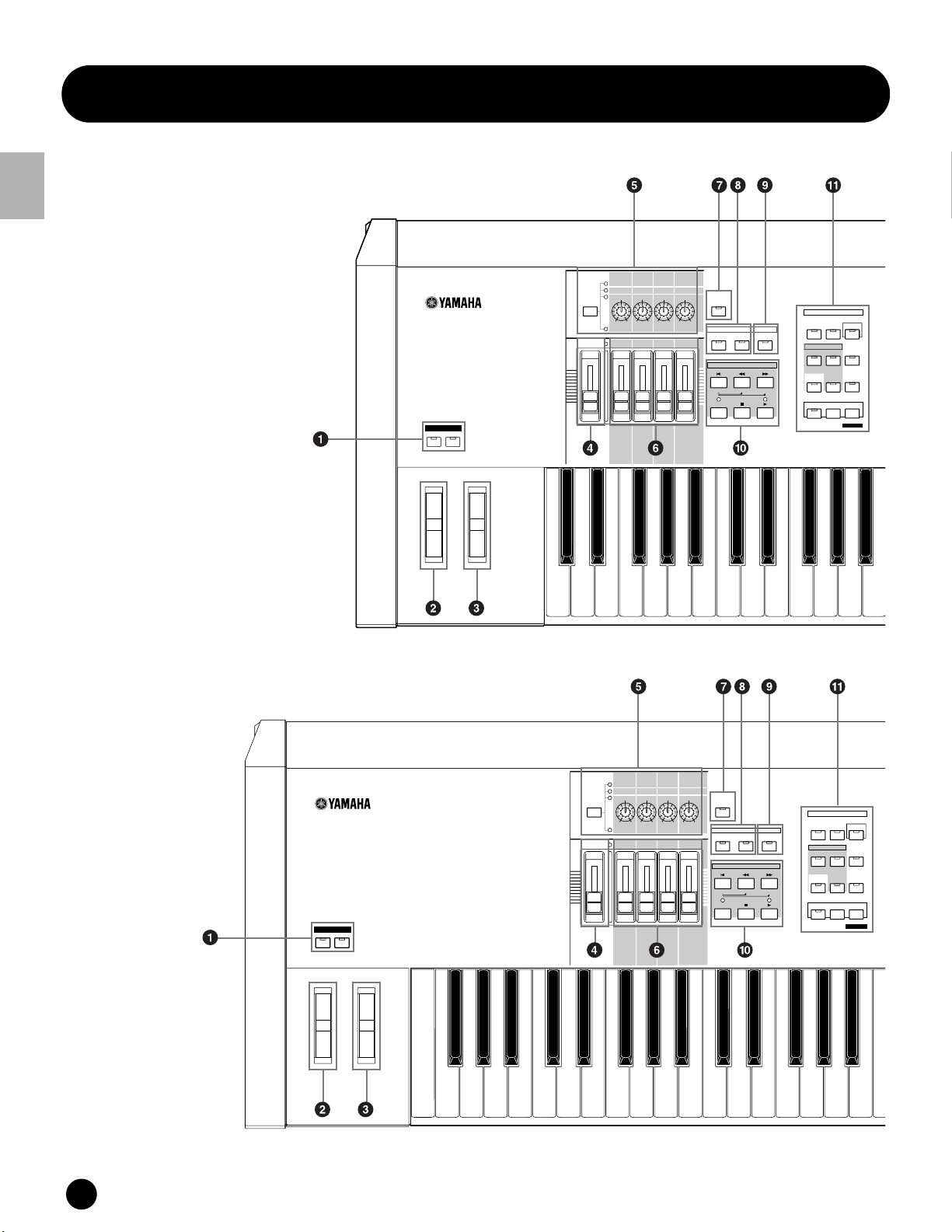
Front Panel
OCTAVE
DOWN
UP
KNOB
CONTROL
FUNCTION
PAN
REVERB
CHORUS
TEMPO
ATTACK RELEASECUTOFF
RESONANCE
ASSIGN A ASSIGN B ASSIGN 1 ASSIGN 2
KN 1 KN 2 KN 3 KN 4
MEQ LOW
MEQ HI MIDMEQLOWMID MEQ HIGH
REMOTE
CONTROL
ON/OFF
EFFECT BYPASS
ARPEGGIO
INSERTION
SYSTEM
ON/OFF
MASTER
VOLUME
VOLUME 1 VOLUME 2 VOLUME 3 VOLUME 4
CS 1 CS 2 CS 3 CS 4
ZONE 1 ZONE 2 ZONE 3 ZONE 4
SEQ
TRANSPORT
LOCATE
1
2
REC
MODE
VOICE PERFORM MASTER
SEQUENCER
SONG
PATTERN
FILE
INTEGRATED
SAMPLING
MIXING
UTILITY
EDIT
JOB
STORE
COMPARE
SCENE STORE
SET LOCATE
OCTAVE
DOWN
UP
KNOB
CONTROL
FUNCTION
PAN
REVERB
CHORUS
TEMPO
ATTAC K RELEASECUTOFF
RESONANCE
ASSIGN A ASSIGN B ASSIGN 1 ASSIGN 2
KN 1 KN 2 KN 3 KN 4
MEQ LOW
MEQ HI MIDMEQLOWMID MEQ HIGH
MASTER
VOLUME
VOLUME 1 VOLUME 2 VOLUME 3 VOLUME 4
CS 1 CS 2 CS 3 CS 4
ZONE 1 ZONE 2 ZONE 3 ZONE 4
REMOTE
CONTROL
ON/OFF
EFFECT BYPASS
ARPEGGIO
INSERTION
SYSTEM
ON/OFF
SEQ
TRANSPORT
LOCATE
1
2
REC
MODE
VOICE PERFORM MASTER
SEQUENCER
SONG
PATTERN
FILE
INTEGRATED
SAMPLING
MIXING
UTILITY
EDIT
JOB
STORE
COMPARE
SCENE STORE
SET LOCATE
The Controls & Connectors
Front Panel
MOTIF6
The Control & Connectors
MOTIF7
10
MOTIF The Controls & Connectors

SONG SCENE
SF 1SF 2SF 3SF 4SF 5
F1 F2 F3 F4 F6F5
INFORMATION
DEC/NO INC/YES
EXIT
EXECUTE
Front Panel
MUSIC
SYNTHESIZER
PRODUCTION
Sequencer
Sampling
Integrated
Real-timeExternal Control
Surface
Modular
Synthesis
Plug-in
System
GM
GUITAR/
PLUCKED
PERCUSSION
12
SLOT 1 SLOT 2 SLOT 3
USER PLG 1
STRINGS
BASS
D
E
F
DRUM/
SE
MUSICAL FX COMBI
PERCUSSION
6
4
5
14
13
PRE 2
PRE 1
DRUM KITS
FAVORITES
COMMON
ENTER
KEYBOARD
A. PIANO
A
SYN LEAD SYN PAD/
1
ELEMENT/PERF.PART /ZONE
9
B
CHOIR
2
10
PRE 3
ORGAN
C
SYN COMP CHROMATIC
3
11
CATEGORY
PLG 3
PLG 2
SEARCH
SECTION
TRACK
SELECT
MUTE
BANK
GROUP
NUMBER
The Control & Connectors
BRASS
REED/PIPE
G
H
7
8
16
15
SOLO
SONG SCENE
SF 1SF 2SF 3SF 4SF 5
F1 F2 F3 F4 F6F5
INFORMATION
DEC/NO INC/YES
EXIT
EXECUTE
MUSIC
SYNTHESIZER
PRODUCTION
Sequencer
Sampling
Integrated
Real-timeExternal Control
Surface
Modular
Synthesis
Plug-in
System
GUITAR/
PLUCKED
PERCUSSION
SLOT 1 SLOT 2 SLOT 3
USER PLG 1
GM
STRINGS
BASS
D
E
F
DRUM/
SE
MUSICAL FX COMBI
PERCUSSION
6
4
5
14
12
13
PRE 2
PRE 1
DRUM KITS
FAVORITES
COMMON
ENTER
KEYBOARD
A. PIANO
A
SYN LEAD SYN PAD/
1
ELEMENT/PERF.PART/ ZONE
9
B
CHOIR
2
10
PRE 3
ORGAN
C
SYN COMP CHROMATIC
3
11
CATEGORY
PLG 3
PLG 2
SEARCH
SECTION
TRACK
SELECT
MUTE
BANK
GROUP
NUMBER
BRASS
REED/PIPE
G
H
7
8
16
15
SOLO
MOTIF The Controls & Connectors
11
Front Panel
MOTIF8
The Control & Connectors
KNOB
ASSIGN A ASSIGN B ASSIGN 1 ASSIGN 2
CONTROL
FUNCTION
MEQ LOW
MASTER
VOLUME 1 VOLUME 2 VOLUME 3 VOLUME 4
VOLUME
ZONE 1 ZONE 2 ZONE 3 ZONE 4
CHORUS
PAN
REVERB
ATTACK RELEASECUTOFF
RESONANCE
KN 1 KN 2 KN 3 KN 4
MEQ HI MIDMEQLOWMID MEQ HIGH
CS 1 CS 2 CS 3 CS 4
TEMPO
REMOTE
CONTROL
ON/OFF
EFFECT BYPASS
INSERTION
SEQ
LOCATE
REC
SYSTEM
TRANSPORT
1
ARPEGGIO
ON/OFF
2
MODE
VOICE PERFORM MASTER
SEQUENCER
SONG
PATTERN
INTEGRATED
SAMPLING
MIXING
EDIT
JOB
COMPARE
FILE
UTILITY
STORE
SCENE STORE
SET LOCATE
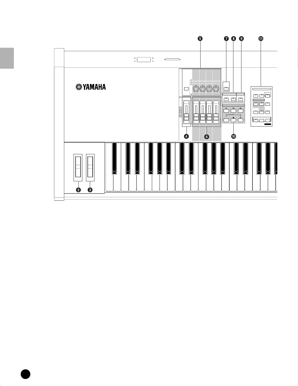
1 OCTAVE [UP] and [DOWN] buttons (page 127)
Use these buttons to change the note range of the
keyboard. To restore the normal octave setting,
press both buttons simultaneously.
n Because of its extended keyboard, the MOTIF 8
does not have OCTAVE buttons.
2 PITCH bend wheel (page 48)
Controls the pitch bend effect. You can also assign
other functions to this controller.
3 MODULATION wheel (page 48)
Controls the modulation effect. You can also assign
other functions to this controller.
4 MASTER VOLUME
Adjusts the volume of the overall sound, as output
from the rear-panel OUTPUT L/MONO and R
jacks as well as the PHONES jack.
5 [KNOB CONTROL FUNCTION] button and
four Knobs (pages 48, 132)
These four highly versatile knobs let you adjust
various aspects or parameters of the current Voice.
Use the [KNOB CONTROL FUNCTION] button to
change the parameter set for the knobs. The
corresponding LED lights to indicate which group
of parameters are active.
12
MOTIF The Controls & Connectors

SONG SCENE
SF 1SF 2SF 3
F1 F2 F3 F4 F6F5
SF 4 SF 5
INFORMATION
DEC/NO INC/YES
EXIT
EXECUTE
Front Panel
MUSIC
SYNTHESIZER
PRODUCTION
Sequencer
Sampling
Integrated
Real-timeExternal Control
Surface
Modular
Synthesis
Plug-in
System
GUITAR/
PLUCKED
PERCUSION
SLOT 1 SLOT 2 SLOT 3
USER PLG 1
GM
STRINGS
BASS
D
E
F
DRUM/
SE
PERCUSION
6
4
5
14
12
13
PRE 2
PRE 1
DRUM KITS
FAVORITES
COMMON
ENTER
KEYBOARD
A. PIANO
A
SYN LEAD SYN PAD/
1
ELEMENT/PERF.PART /ZONE
9
B
CHOIR
2
10
PRE 3
ORGAN
C
SYN COMP CHROMATIC
3
11
PLG 2
BRASS
REED/PIPE
G
MUSICAL FX COMBI
7
15
CATEGORY
PLG 3
SEARCH
BANK
SECTION
H
8
16
SELECT
GROUP
TRACK
NUMBER
MUTE
SOLO
The Control & Connectors
6 [CS1] - [CS4] (Control Slider) (page 48)
Controls the volume of each part/element.
In the Master mode, the Zone setting (page 271)
allows you to assign various functions (Control
Change numbers) to these Sliders other than the
volume.
7 [REMOTE CONTROL ON/OFF] button
(page 256)
When this is on, the following panel controls can be
used to directly control mixing and transport
functions on your sequencer software.
• Knobs
• Control Sliders
• [SEQ TRANSPORT] buttons
• [TRACK SELECT] button
• [MUTE] button
8 [EFFECT BYPASS] buttons
For enabling/disabling Effect Bypass. Press the
button (the LED lights) to bypass effect processing
of the current Voice or Performance.
The bypassed effects (Reverb, Chorus, Variation, or
Insertion) are specified in the Utility Mode
(page 250).
9 [ARPEGGIO ON/OFF] button (page 55)
Press this button to enable or disable playback of
the Arpeggio for each Voice, Performance, Song, or
Pattern. If the Arpeggio Switch of the selected part
is set to off in the Performance/Song/Pattern mode,
however, pressing this button has no effect.
MOTIF The Controls & Connectors
13

Front Panel
) SEQ TRANSPORT buttons
(page 78, 179, 183, 217, 221)
These buttons control recording and playback of the
Song/Pattern sequence data.
[](Top) button
Instantly returns to the first beginning of the
current song or pattern (i.e., the first beat of the first
The Control & Connectors
measure).
[](Reverse) button
Press briefly to move back one measure at a time, or
hold to continuously rewind.
[](Forward) button
Press briefly to move forward one measure at a time,
or hold to continuously fast-forward.
[REC] (Record) button
Press this to enable recording (Song or pattern
phrase). (The indicator lights.)
[](Stop) button
Press to stop recording or playback.
% [SF1] - [SF5] (Sub Function) buttons (page 71)
These buttons located directly below the LCD
display call up the corresponding sub functions
indicated in the display. In the display hierarchy,
these sub functions [SF] rank just below the
functions [F].
These buttons can be also used to store/recall the
Song Scene (page 115) in the Song Play/Song
Record/Pattern Chain Record modes.
^ [INFORMATION] button (page 73)
For calling up a special “help” feature that shows
information about the currently selected mode. You
can go back to the previous display by pressing this
button again or pressing any other button.
& Data dial (page 72)
For editing (changing the value of) the currently
selected parameter. To increase the value, turn the
dial right (clockwise); to decrease the value, turn the
dial left (counter-clockwise). If a parameter with a
wide value range is selected, you can change the value
in broader strokes by quickly turning the dial.
[](Play) button
Press to start playback from the current point in the
song or pattern. During recording and playback, the
indicator flashes at the current tempo.
! MODE buttons (page 67)
These buttons select the MOTIF operating modes
(e.g., Voice mode).
@ LCD Display
The MOTIF’s large backlit LCD displays the
parameters and values related to the currently
selected operation or mode.
# LCD Contrast Control
Use this control to set the LCD display for optimum
legibility.
$ [F1] - [F6] (Function) buttons (page 71)
These buttons located directly below the LCD
display call up the corresponding functions
indicated in the display. In the display hierarchy,
these functions [F] rank just below the modes.
* [INC/YES] button (page 72)
For increasing the value of the currently selected
parameter. Also use it to actually execute a Job or a
Store operation.
( [DEC/NO] button (page 72)
For decreasing the value of the currently selected
parameter. Also use it to cancel a Job or a Store
operation.
n When editing (changing) the value of the
parameter, it is convenient to use the [INC/YES]
button and the [DEC/NO] button simultaneously.
Pressing the [DEC/NO] button while holding the
[INC/YES] button increases the value by 10.
Pressing the [INC/YES] button while holding the
[DEC/NO] button decreases the value by 10.
º Cursor Buttons (page 72)
The cursor buttons move the “cursor” around the
LCD display screen, highlighting and selecting the
various parameters.
¡ [EXIT] button (page 72)
The menus and displays of the MOTIF are
organized according to a hierarchical structure.
Press this button to exit from the current display
and return to the previous level in the hierarchy.
14
MOTIF The Controls & Connectors
Front Panel
™ [ENTER] button
Use this button to execute a Job or a Store
operation. Also use this button to actually enter a
number when selecting a Memory or Bank for Voice
or Performance. In the File mode, use this button to
go to the next lowest level in the selected directory.
£ SLOT 1-3 lamps (page 282)
These three lamps show the installation status of
the Plug-in Boards.
If the Plug-in Board has been correctly installed, the
corresponding SLOT lamp will light.
n The Vocal Harmony Plug-in Board (PLG100-VH)
can be installed only to slot 1. It cannot be installed
to slot 2 or 3.
n The Multi part Plug-in Board (PLG100-XG) can be
installed only to slot 3. It cannot be installed to slot
1 or 2.
¢ BANK buttons (page 124)
Each button selects a Voice or Performance Bank.
When the [CATEGORY SEARCH] button is turned
on, these buttons can be used to select the desired
category (printed below each button). When the
[SECTION] button is turned on in the Pattern
mode, these buttons are used to select the desired
section.
∞ GROUP [A] - [H] buttons (page 124)
Each button selects a Voice or Performance Group.
When the [CATEGORY SEARCH] button is turned
on, these buttons can be used to select the desired
category (printed below each button). When the
[SECTION] button is turned on in the Pattern
mode, these buttons are used to select the desired
section.
§ NUMBER [1] - [16] buttons (page 124)
Use of these buttons differs depending on the on/off
status of the [TRACK SELECT] and [MUTE]
buttons.
Functions of the NUMBER [1] - [16] buttons
Voice Play mode
Voice Edit mode
Performance Play
mode
Performance Edit
mode
Master Play mode
Master Edit mode
Song/Pattern
mode
Song/Pattern
Mixing mode
When [TRACK
SELECT] is on
Keyboard transmit
channel setting
Element selection(1 - 4) and Element
Mute setting(9 - 12)
Keyboard transmit
channel setting
Performance part
selection (1 - 4)
Zone selection
(1 - 4)
Zone selection
(1 - 4)
Song/Pattern
track selection
Song/Pattern part
selection
When [MUTE]
is on
—
Performance part
Mute setting
(1 - 4)
—
Zone Mute setting
(1 - 4)
Song/Pattern
track Mute setting
Song/Pattern part
Mute setting
When both
[TRACK SELECT]
[MUTE] are off
Voice selection,
according to Groups
A - H
—
Performance or
Voice selection (if
cursor is located at
Voice name),
according to Groups
A - H
Master selection,
according to Groups
A - H
—
Song/Style selection,
according to Groups
A - H
¶ [CATEGORY SEARCH] button (page 126)
When this button is turned on in the Performance
mode, the [BANK] and [GROUP] buttons can be
used to select the Performance category.
When this button is turned on in another mode, the
[BANK] and [GROUP] buttons can be used to select
the Voice category.
• [SECTION] button (page 218)
When this button is turned on in the Pattern mode,
the [BANK] and [GROUP] buttons can be used to
select the Pattern Section.
ª [TRACK SELECT] button (page 181)
Turning this button on in the Song/Pattern mode
enables the NUMBER [1] - [16] buttons for
selecting corresponding Song/Pattern tracks. The
on/off status of this button affects the NUMBER [1]
- [16] buttons in different ways, depending on the
selected mode. (See § “NUMBER [1] - [16]
buttons” above.)
The Control & Connectors
‚ [MUTE] button (page 180)
Turning this button on in the Song/Pattern mode
enables the NUMBER [1] - [16] buttons for muting
corresponding Song/Pattern tracks.
Press one of the NUMBER [1] - [16] buttons while
holding this button to solo the corresponding track
of the current selected Song/Pattern.
The on/off status of this button affects the
NUMBER [1] - [16] buttons in different ways,
depending on the selected mode. (See § “NUMBER
[1] - [16] buttons” above.)
MOTIF The Controls & Connectors
15

Rear Panel
Rear Panel
MOTIF6
The Control & Connectors
MOTIF7
POWER
ON
CAUTION
POWER
ON
OFF
OFF
AC
INLET
CAUTION
AC
INLET
O
EXPANSION
I
mLAN
O
EXPANSION
I
mLAN
MOTIF8
POWER
OFF
ON
16
MOTIF The Controls & Connectors
CAUTION
RISK OF ELECTRIC SHOCK
DO NOT OPEN
:RISQUE DE CHOC ÉLECTRIQUE NE PAS OUVRIR.
ATTENTION
WARNING
TO REDUCE THE RISK OF FIRE OR ELECTRIC
SHOCK, DO NOT EXPOSE THIS PRODUCT TO RAIN OR MOISTURE.
AC
INLET
THIS DEVICE COMPLIES WITH PART 15 OF THE FCC RULES. OPERATION IS SUBJECT TO
THE FOLLOWING TWO CONDITIONS:
(1) THIS DEVICE MAY NOT CAUSE HARMFUL INTERFERENCE, AND
(2) THIS DEVICE MUST ACCEPT ANY INTERFERENCE RECEIVED, INCLUDINGINTERFERENCE
THAT MAY CAUSE UNDESIRED OPERATION.
THIS CLASS B DEIGITAL APPARATUS COMPLIES WITH CANADIAN ICES-003.
CET APPAREIL NUMÉRIQUE DE LA CLASSE B EST CONFORME À LA NORME NMB-003
DU CANADA.
O
EXPANSION
I
mLAN
Rear Panel
Rear Panel
3
3.3V
CARD
Plug-in SLOT
GREEN
YELLOW
2
ORANGE
1
OPTICAL
OUTPUT USB THRU
OPTICAL
OUTPUT
USB
THRU
SCSI
MIDI
OUT
IN
BREATH
ASSIGNABLE
FOOT
SWITCH
SUSTAIN
FOOT
CONTROLLER
1RL
2
ASSIGNABLE
OUTPUT
OUTPUT
MONO
L
R
PHONES
A
D
INPUT
GAIN
R
L
The Control & Connectors
3
R
Plug-in SLOT
OUTPUT
L MONO
2
1
PHONES
GREEN
YELLOW
ORANGE
A
D
INPUT
GAIN
R
L
3.3V
CARD
SCSI
MIDI
OUT
IN
BREATH
ASSIGNABLE
SWITCH
FOOT
FOOT
CONTROLLER
ASSIGNABLE
OUTPUT
1
2
SUSTAIN
RL
OPTICAL
OUTPUT
3.3V
BREATH
ASSIGNABLE
SWITCH
CARD
FOOT
FOOT
CONTROLLER
SUSTAIN
12
ASSIGNABLE
RL
OUTPUT
R
OUTPUT
L MONO
A D INPUT
GAIN
R
PHONES
L
MOTIF The Controls & Connectors
17
SCSI
3
GREEN
YELLOW
2
ORANGE
Plug-in SLOT
USB
1
MIDI
OUT
THRU
IN

Rear Panel
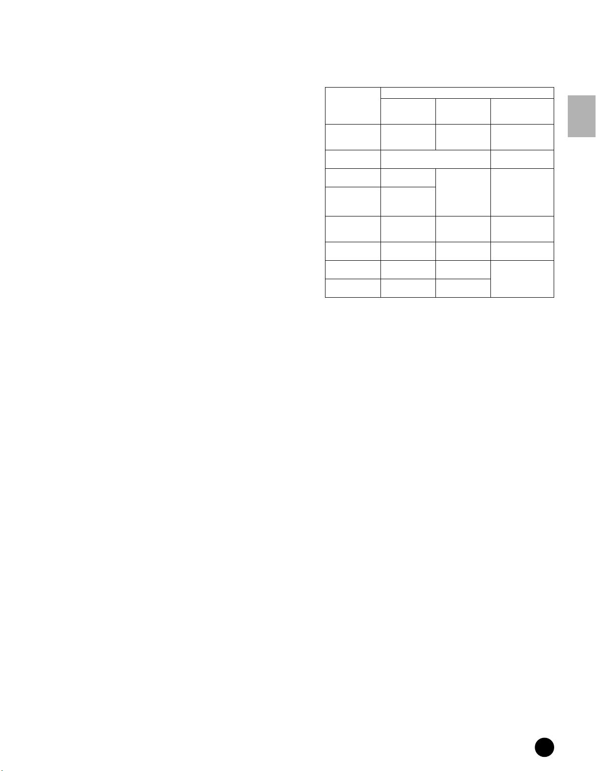
1 POWER Switch (page 29)
Press to turn power ON or OFF.
2 AC Power Cord Socket (page 20)
Be sure the plug the AC power cord into this socket
before plugging the power cord into an AC outlet.
Use only the AC power cord supplied with the
MOTIF. If the supplied cord is lost or damaged and
The Control & Connectors
needs to be replaced, contact your Yamaha dealer.
The use of an inappropriate replacement can pose a
fire and shock hazard!
3 mLAN expansion board (mLAN8E) or I/O
expansion board (AIEB2) cover (page 22)
Either the mLAN expansion board (mLAN8E) or
the I/O expansion board (AIEB2) sold separately
can be installed to the MOTIF.
With the mLAN8E board, you can conveniently
and easily hook up your MOTIF to other mLANcompatible instruments or devices. The AIEB2
board gives you additional digital I/O options,
featuring both optical and coaxial connectors.
Moreover, the board also includes three stereo
ASSIGNABLE OUTPUT pairs (six analog jacks).
4 OPTICAL OUT connectors (page 22)
For output of digital audio, via optical fiber cables
(at 44.1kHz).
5 USB connector (page 25)
For connection to a computer having a USB
interface. The USB interface provides multi-port
MIDI operation not possible with a single MIDI
connection.
n The USB connection can only be used for transfer of
MIDI data. No audio data can be transfered via USB.
USB
USB is an abbreviation for Universal Serial Bus. It is
a serial interface for connecting a computer with
peripheral devices, and enables much faster data
transfer (12Mbps) compared to conventional serial
port connections. Also, it allows “hot swapping”
(connecting peripheral devices while the power to
the computer is on).
6 MIDI IN/OUT/THRU connectors (page 24)
MIDI IN is for receiving control or performance
data from another MIDI device, such as an external
sequencer.
MIDI THRU is simply for redirecting any received
MIDI data (via MIDI IN) to connected devices,
allowing convenient chaining of additional MIDI
instruments.
MIDI OUT is for transmitting all control,
performance and playback data from the MOTIF to
another MIDI device, such as an external sequencer.
7 BREATH Controller Jack (page 28)
Connect an optional Yamaha BC2 Breath Controller
here for expressive breath control capability.
8 FOOT SWITCH jacks (page 28)
For connection of optional FC4 or FC5
Footswitches. When connected to the SUSTAIN
jack, the Footswitch controls sustain. When
connected to ASSIGNABLE, it can control one of
various different assignable functions.
9 FOOT CONTROLLER jacks (page 28)
For connection of optional foot controllers (FC7,
etc.). Each jack lets you continuously control one of
various different assignable functions — such as
volume, tone, pitch, or other aspects of the sound.
) ASSIGNABLE OUT L and R jacks (page 21)
Line level audio signals are output from the MOTIF
via these phone jacks (1/4" mono phone plug).
These outputs are independent of the main output
(at the L/MONO and R jacks below), and can be
freely assigned to any of the Parts. This lets you
route specific Voices or sounds for processing with a
favorite outboard effect unit.
! OUTPUT L/MONO and R jacks (page 21)
Line level audio signals are output via these phone
jacks. For monophonic output, use just the L/
MONO jack.
@ PHONES jack (page 21)
For connection to a pair of stereo headphones.
# A/D INPUT jacks (page 23)
External audio signals can be input via these phone
jacks. These are used primarily for recording
samples — either with a microphone, making the
proper Utility settings (page 250), or from other
audio equipment, such as a CD or MD player. With
the optional Vocal Harmony Plug-in board
(PLG100-VH, page 35), you can also apply special
effects and harmonies to the microphone input.
$ GAIN knob
For adjusting the input gain of the audio at the A/D
INPUT jacks (above). Depending on the connected
device (microphone, CD player, etc.), you may need
to adjust this for optimum level.
% SCSI connectors (page 27)
This SCSI-2 50-pin connector (D-sub, half-pitch)
can be used to connect to an external SCSI data
storage device — allowing you to conveniently save
and store large quantities of data.
18
MOTIF The Controls & Connectors
Rear Panel
^ Card slot (pages 64, 262)
Insert a Memory Card here to transfer various data
to/from the MOTIF. Read carefully the precautions
on using a Memory Card (page 289) before
inserting a card.
& Plug-in board cover (page 35)
Installing an optional Plug-in Board to the MOTIF
lets you greatly expand the sonic palette of the
instrument. Up to three boards can be installed to
the MOTIF’s rear panel.
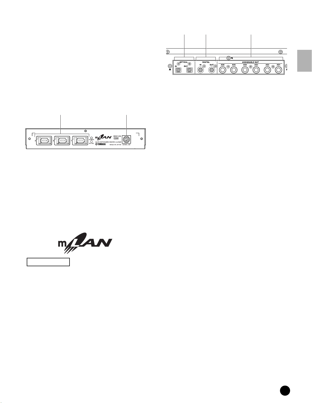
■ When the optional mLAN8E has been installed:
12
1 SERIAL I/O connector
For connecting the mLAN8E directly to a personal
computer via a serial cable. Use this jack to connect
the mLAN8E and the computer when using the
mLAN Patchbay and mLAN Mixer in Windows.
This is not used to input or output MIDI or audio
signals.
2 mLAN (IEEE1394) connector1, 2, 3
For connecting mLAN devices or IEEE1394compatible devices via IEEE1394 standard (6-pin)
cables.
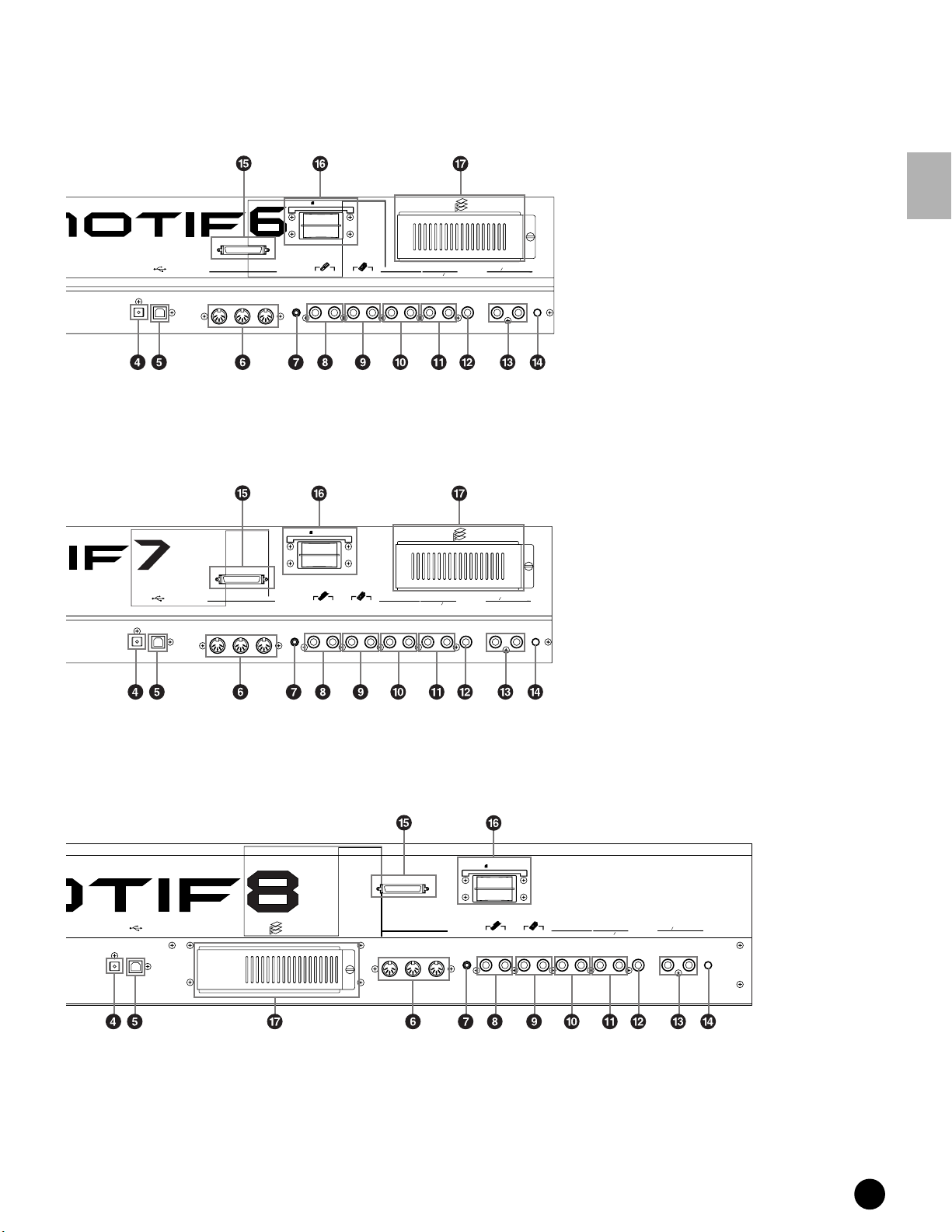
■ When the optional AIEB2 has been installed:
1 2 3
1 OPTICAL IN, OUT connectors (pages 22, 23)
Use these connectors to input or output digital
signals over optical-fiber cable. You can use the
OPTICAL IN to record a digital signal of frequency
48kHz, 44.1kHz, or 32kHz. The OPTICAL OUT
connector outputs a digital signal of frequency
44.1kHz.
2 DIGITAL IN, OUT connectors (pages 22, 23)
Use these connectors to input or output digital
signals over coaxial (RCA-pin) cable. The digital
signal format is CD/DAT (S/P DIF). You can use
the DIGITAL IN connector to record a digital signal
of frequency 48kHz, 44.1kHz, or 32kHz. The
DIGITAL OUT connector outputs a digital signal of
frequency 44.1kHz.
3 ASSIGNABLE OUT jacks (AS1 to AS6)
(page 22)
Additional analog output jacks. Each pair (1&2,
3&4, 5&6) operates independently of all other
outputs on the MOTIF.
The Control & Connectors
About mLAN
“mLAN” is a digital network designed for musical
applications. It uses and extends the industry
standard IEEE 1394 high performance serial bus.
For details, refer to the Guide Book of the
mLAN8E.
The name “mLAN” and its logo (above) are
trademarks.
MOTIF The Controls & Connectors
19
Power Supply
Setting Up
This section explains how to connect your MOTIF to an AC power source, external audio and MIDI devices, and a
computer system. Only switch the MOTIF on after you have made all the necessary connections.
It is recommended that you read this section before using the MOTIF.
Power Supply
Setting Up
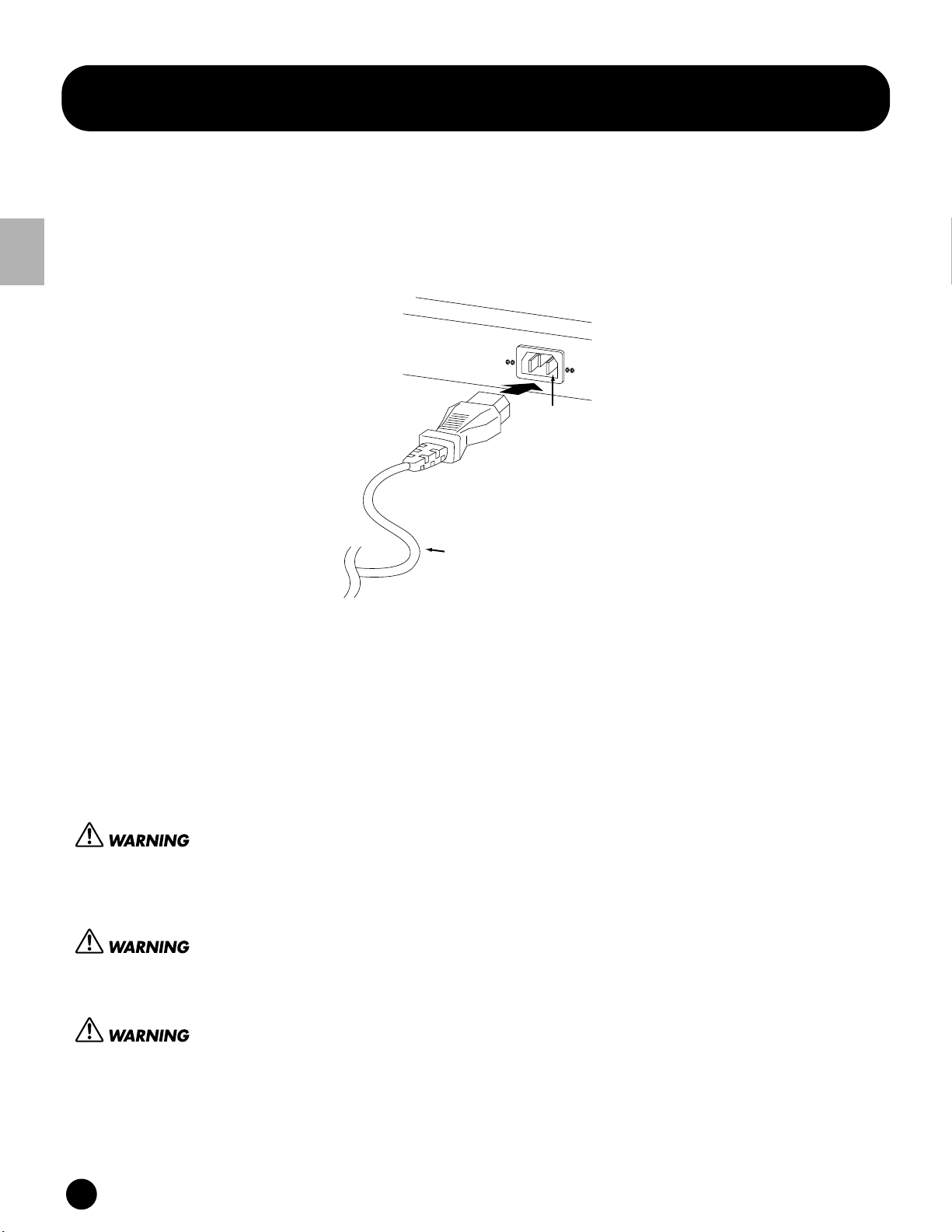
rear panel
AC INLET terminal
Power cord
(included)
1 Make sure the POWER switch on the MOTIF is set to OFF.
2 Connect the supplied power cord to the AC INLET terminal on the instrument’s rear panel.
3 Connect the other end of the power cord to an AC outlet. Make sure your MOTIF meets the voltage requirement
for the country or region in which it is being used.
Make sure your MOTIF is rated for the AC voltage supplied in the area in which it is to be used (as listed on the rear
panel). Connecting the unit to the wrong AC supply can cause serious damage to the internal circuitry and may even
pose a shock hazard!
Use only the AC power cord supplied with the MOTIF. If the supplied cord is lost or damaged and needs to be
replaced, contact your Yamaha dealer. The use of an inappropriate replacement can pose a fire and shock hazard!
The type of AC power cord provided with the MOTIF may be different depending on the country in which it is
purchased (a third prong may be provided for grounding purposes). Improper connection of the grounding conductor
can create the risk of electrical shock. Do NOT modify the plug provided with the MOTIF. If the plug will not fit the
outlet, have a proper outlet installed by a qualified electrician. Do not use a plug adapter which defeats the grounding
conductor.
20
MOTIF Setting Up
Connections
Connections
Connecting to External Audio Equipment
Since the MOTIF has no built-in speakers, you’ll need an external audio system or a set of stereo headphones to
properly monitor it. The following illustrations show various connection examples; use the one most similar to your
intended setup.
Analog output
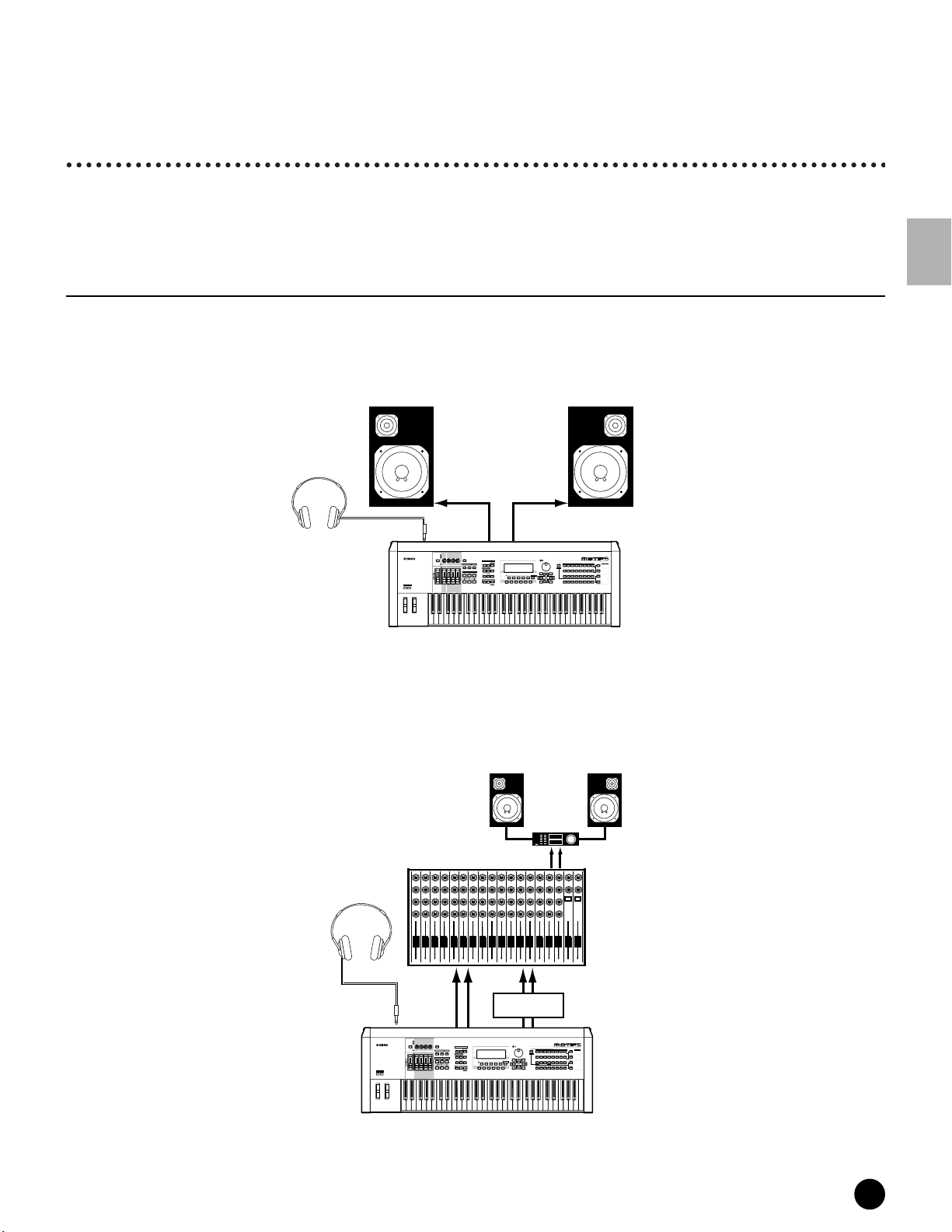
■ Connecting stereo powered speakers
A pair of powered speakers can accurately produce the instrument’s rich sounds with their own pan and effect
settings. Connect your powered speakers to the OUTPUT L/MONO and R jacks on the rear panel.
Powered speaker (Left) Powered speaker (Right)
Headphones
Setting Up
PHONES
OCTAVE
DOWN
OUTPUT
L /MONO
PAN
CHORUS
REVERB
TEMPO
ATTACK RELEASECUTOFF
RESONANCE
KNOB
REMOTE
ASSIGN A ASSIGN B ASSIGN 1 ASSIGN 2
CONTROL
CONTROL
FUNCTION
ON/OFF
KN 1 KN 2 KN 3 KN 4
MEQ LOW
MEQ HI MIDMEQLOWMID MEQ HIGH
ARPEGGIO
EFFECT BYPASS
SYSTEM
ON/OFF
INSERTION
MASTER
VOLUME 1VOLUME 2 VOLUME 3 VOLUME 4
VOLUME
SEQ
TRANSPORT
LOCATE
1
REC
CS 1 CS 2 CS 3 CS 4
UP
ZONE 1 ZONE 2 ZONE 3 ZONE 4
R
MUSIC
SYNTHESIZER
PRODUCTION
Sequencer
Sampling
Integrated
Real-timeExternalControl
Surface
Modular
Synthesis
Plug-in
System
MODE
VOICE PERFORM MASTER
SEQUENCER
SONG
PATTERN FILE
INTEGRATED
SAMPLING
UTILITY
MIXING
SONG SCENE
INFORMATION
SF 1SF 2SF 3SF 4SF 5
2
EDIT
STORE
JOB
F1 F2 F3 F4 F6F5
SCENE STORE
COMPARE
SET LOCATE
DEC/NO INC/YES
EXIT
SLOT 1 SLOT 2 SLOT 3
CATEGORY
PRE 2
PRE 1
PRE 3
PLG 3
USER PLG 1
PLG 2
DRUM KITS
GM
SEARCH
BANK
GUITAR/
KEYBOARD
BRASS
A. PIANO
STRINGS
REED/PIPE
ORGAN
FAVORITES
BASS
PLUCKED
COMMON
D
B
E
SECTION
A
C
FGH
GROUP
DRUM/
SYN COMPCHROMATIC
SE
SYN LEAD SYN PAD/
MUSICAL FX COMBI
PERCUSSION
PERCUSSION
CHOIR
TRACK
1
34567
2
8
SELECT
ELEMENT/PERF.PART/ZONE
NUMBER
11
12
10
131416
9
ENTER
MUTE
15
EXECUTE
SOLO
MOTIF
n When using just one powered speaker, connect it to the OUTPUT L/MONO jack on the rear panel.
■ Connecting to a mixer
There are extra audio outputs in addition to the OUTPUT (L/MONO and R) jacks. Connect these outputs to a mixer
for separately controlling the outputs of up to four Parts in Performance mode (page 164).
Speaker
Amplifier
Headphones
L
Mixer
12345678910111213141516LR
OUTPUT L
R
R
PHONES
OCTAVE
DOWN
VOICE PERFORM MASTER
SEQUENCER
SONG
INTEGRATED
SAMPLING
EDIT
COMPARE
MODE
PATTERN FILE
UTILITY
MIXING
STORE
JOB
SCENE STORE
SET LOCATE
R
SONG SCENE
SF 1SF 2SF 3SF 4SF 5
F1 F2 F3 F4 F6F5
ASSIGNABLE
OUTPUT L, R
MUSIC
PRODUCTION
Integrated
Real-timeExternalControl
Modular
PRE 2
PRE 1
PRE 3
DRUM KITS
KEYBOARD
A. PIANO
ORGAN
FAVORITES
COMMON
B
A
C
DEC/NO INC/YES
SYN COMPCHROMATIC
SYN LEAD SYN PAD/
CHOIR
1
2
INFORMATION
ELEMENT/PERF.PART/ZONE
11
10
9
ENTER
EXIT
EXECUTE
SYNTHESIZER
Sampling
Synthesis
GM
GUITAR/
PLUCKED
D
PERCUSSION
34567
12
Sequencer
Surface
Plug-in
System
SLOT 1 SLOT 2 SLOT 3
CATEGORY
PLG 3
USER PLG 1
PLG 2
SEARCH
BANK
BRASS
STRINGS
REED/PIPE
BASS
SECTION
E
FGH
GROUP
DRUM/
SE
MUSICAL FX COMBI
PERCUSSION
TRACK
8
SELECT
NUMBER
131416
MUTE
15
SOLO
OUTPUT
L/MONO
PAN
CHORUS
REVERB
TEMPO
ATTACK RELEASECUTOFF
RESONANCE
KNOB
REMOTE
ASSIGN A ASSIGN B ASSIGN 1 ASSIGN 2
CONTROL
CONTROL
FUNCTION
ON/OFF
KN 1 KN 2 KN 3 KN 4
MEQ LOW
MEQ HI MIDMEQLOWMID MEQ HIGH
ARPEGGIO
EFFECT BYPASS
SYSTEM
ON/OFF
INSERTION
MASTER
VOLUME 1VOLUME 2 VOLUME 3 VOLUME 4
VOLUME
SEQ
TRANSPORT
2
LOCATE
1
REC
CS 1 CS 2 CS 3 CS 4
UP
ZONE 1 ZONE 2 ZONE 3 ZONE 4
MOTIF
MOTIF Setting Up
21
Connections
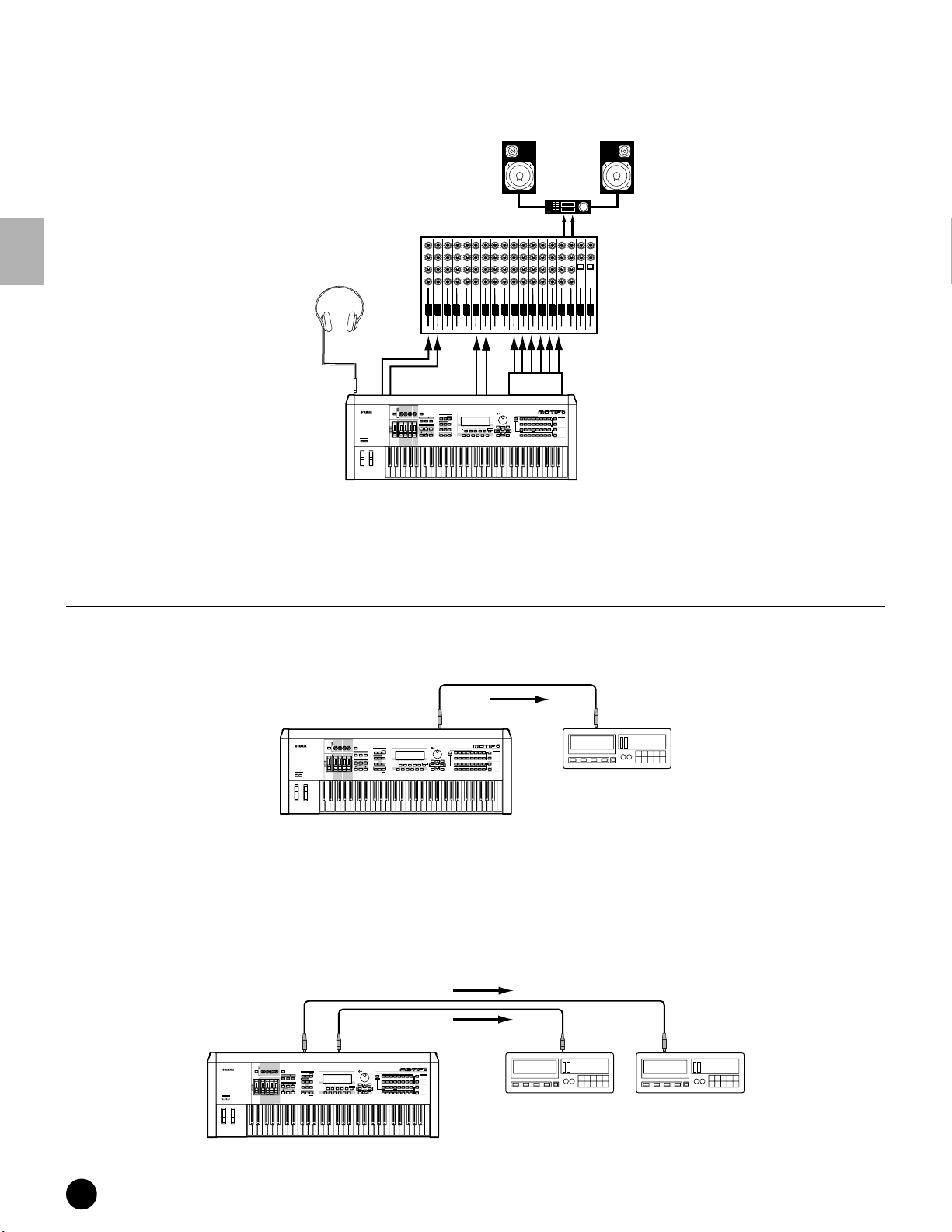
■ Connecting to a mixer (with the optional AIEB2)
You can expand the MOTIF’s output capabilties with six additional OUTPUT jacks for outputting extra individual
parts, by installing the optional I/O board (AIEB2).
Speaker
Mixer
L
OUTPUT L
Amplifier
R
R
Headphone
Setting Up
12345678910111213141516LR
ASSIGNABLE
R
PAN
CHORUS
REVERB
TEMPO
ATTACK RELEASECUTOFF
RESONANCE
KNOB
ASSIGN A ASSIGN B ASSIGN 1 ASSIGN 2
CONTROL
FUNCTION
KN 1 KN 2 KN 3 KN 4
MEQ LOW
MEQ HI MIDMEQLOWMID MEQ HIGH
MASTER
VOLUME 1VOLUME 2 VOLUME 3 VOLUME 4
VOLUME
CS 1 CS 2 CS 3 CS 4
ZONE 1 ZONE 2 ZONE 3 ZONE 4
OUTPUT L
REMOTE
CONTROL
ON/OFF
MODE
VOICE PERFORM MASTER
ARPEGGIO
EFFECT BYPASS
SYSTEM
ON/OFF
INSERTION
SEQUENCER
SONG
PATTERN FILE
SEQ
TRANSPORT
INTEGRATED
SAMPLING
MIXING
2
LOCATE
1
REC
EDIT
JOB
COMPARE
R
DRUM KITS
FAVORITES
COMMON
SONG SCENE
SF 1SF 2SF 3SF 4SF 5
F1 F2 F3 F4 F6F5
DEC/NO INC/YES
INFORMATION
ENTER
EXIT
EXECUTE
UTILITY
STORE
SCENE STORE
SET LOCATE
AIEB2
MUSIC
SYNTHESIZER
PRODUCTION
Sequencer
Sampling
Integrated
Real-timeExternalControl
Modular
Synthesis
Plug-in
PRE 2
PRE 1
PRE 3
GM
GUITAR/
KEYBOARD
A. PIANO
ORGAN
PLUCKED
D
B
A
C
SYN COMPCHROMATIC
SYN LEAD SYN PAD/
PERCUSSION
CHOIR
1
34567
2
ELEMENT/PERF.PART/ZONE
11
12
10
9
Surface
System
USER PLG 1
BASS
E
DRUM/
PERCUSSION
131416
SLOT 1 SLOT 2 SLOT 3
CATEGORY
PLG 3
PLG 2
SEARCH
BANK
BRASS
STRINGS
REED/PIPE
SECTION
FGH
GROUP
SE
MUSICAL FX COMBI
TRACK
8
SELECT
NUMBER
MUTE
15
SOLO
PHONES
OUTPUT
L/MONO
OCTAVE
UP
DOWN
MOTIF
n Connecting a pair of headphones does not affect audio output from the OUTPUT (L/MONO and R) jacks. You can monitor the
same sounds via headphones and at the OUTPUT jacks.
Digital output
■ When using the OPTICAL OUTPUT connector:
This connector enables direct digital output of MOTIF playback and digital through-put.
OPTICAL
OUTPUT
PAN
CHORUS
REVERB
TEMPO
ATTACK RELEASECUTOFF
RESONANCE
KNOB
REMOTE
ASSIGN A ASSIGN B ASSIGN 1 ASSIGN 2
CONTROL
CONTROL
FUNCTION
ON/OFF
MODE
KN 1 KN 2 KN 3 KN 4
VOICE PERFORM MASTER
MEQ LOW
MEQ HI MIDMEQLOWMID MEQ HIGH
ARPEGGIO
EFFECT BYPASS
SYSTEM
ON/OFF
INSERTION
MASTER
VOLUME 1VOLUME 2 VOLUME 3 VOLUME 4
VOLUME
SEQUENCER
SONG
PATTERN FILE
SEQ
TRANSPORT
INTEGRATED
SAMPLING
UTILITY
MIXING
SONG SCENE
SF 1SF 2SF 3SF 4SF 5
2
LOCATE
1
REC
EDIT
STORE
JOB
F1 F2 F3 F4 F6F5
SCENE STORE
COMPARE
CS 1 CS 2 CS 3 CS 4
OCTAVE
UP
DOWN
ZONE 1 ZONE 2 ZONE 3 ZONE 4
SET LOCATE
DRUM KITS
FAVORITES
COMMON
DEC/NO INC/YES
INFORMATION
ENTER
EXIT
EXECUTE
Record
MUSIC
SYNTHESIZER
PRODUCTION
Sequencer
Sampling
Integrated
Real-timeExternalControl
Surface
Modular
Synthesis
Plug-in
System
SLOT 1 SLOT 2 SLOT 3
CATEGORY
PRE 2
PRE 1
PRE 3
PLG 3
PLG 2
USER PLG 1
GM
SEARCH
BANK
GUITAR/
KEYBOARD
BRASS
STRINGS
A. PIANO
REED/PIPE
ORGAN
BASS
PLUCKED
D
B
SECTION
E
A
C
FGH
GROUP
DRUM/
SYN COMPCHROMATIC
SE
SYN LEAD SYN PAD/
MUSICAL FX COMBI
PERCUSSION
PERCUSSION
CHOIR
TRACK
1
34567
2
8
SELECT
ELEMENT/PERF.PART/ZONE
NUMBER
11
12
10
131416
9
MUTE
15
SOLO
OPTICAL
INPUT
DAT
DAT or CD recorder
MOTIF
■ When the optional AIEB2 I/O board has been installed:
The board enables direct digital output of MOTIF sound also via the coaxial cable.
For purposes of compatibility, the AIEB2 board includes two different output types: OPTICAL OUT (optical fiber)
and DIGITAL OUT (coaxial cable). Note that both of these outputs always produce identical signals.
Optical cable
Coaxial cable
OPTICAL
OUTPUT
PAN
CHORUS
REVERB
TEMPO
ATTACK RELEASECUTOFF
RESONANCE
KNOB
REMOTE
ASSIGN A ASSIGN B ASSIGN 1 ASSIGN 2
CONTROL
CONTROL
FUNCTION
ON/OFF
KN 1 KN 2 KN 3 KN 4
MEQ LOW
MEQ HI MIDMEQLOWMID MEQ HIGH
ARPEGGIO
EFFECT BYPASS
SYSTEM
ON/OFF
INSERTION
MASTER
VOLUME 1VOLUME 2 VOLUME 3 VOLUME 4
VOLUME
SEQ
TRANSPORT
2
LOCATE
1
REC
CS 1 CS 2 CS 3 CS 4
OCTAVE
UP
DOWN
ZONE 1 ZONE 2 ZONE 3 ZONE 4
DIGITAL
OUTPUT
MUSIC
SYNTHESIZER
PRODUCTION
Sequencer
Sampling
Integrated
Real-timeExternalControl
Surface
Modular
Synthesis
Plug-in
System
MODE
VOICE PERFORM MASTER
SEQUENCER
SONG
PATTERN FILE
INTEGRATED
SAMPLING
UTILITY
MIXING
SONG SCENE
INFORMATION
SF 1SF 2SF 3SF 4SF 5
EDIT
STORE
JOB
F1 F2 F3 F4 F6F5
SCENE STORE
COMPARE
SET LOCATE
DEC/NO INC/YES
SLOT 1 SLOT 2 SLOT 3
PRE 2
PRE 1
PRE 3
PLG 3
PLG 2
DRUM KITS
USER PLG 1
GM
GUITAR/
BRASS
KEYBOARD
STRINGS
A. PIANO
REED/PIPE
ORGAN
FAVORITES
BASS
PLUCKED
COMMON
D
B
E
A
C
FGH
DRUM/
SE
SYN COMPCHROMATIC
MUSICAL FX COMBI
SYN LEAD SYN PAD/
PERCUSSION
PERCUSSION
CHOIR
1
34567
2
8
ELEMENT/PERF.PART/ZONE
11
12
10
131416
9
ENTER
EXIT
15
EXECUTE
MOTIF
Record
Record
CATEGORY
SEARCH
BANK
SECTION
GROUP
TRACK
SELECT
NUMBER
MUTE
SOLO
DIGITAL
INPUT
DAT DAT
OPTICAL
INPUT
DAT or CD recorder
22
MOTIF Setting Up
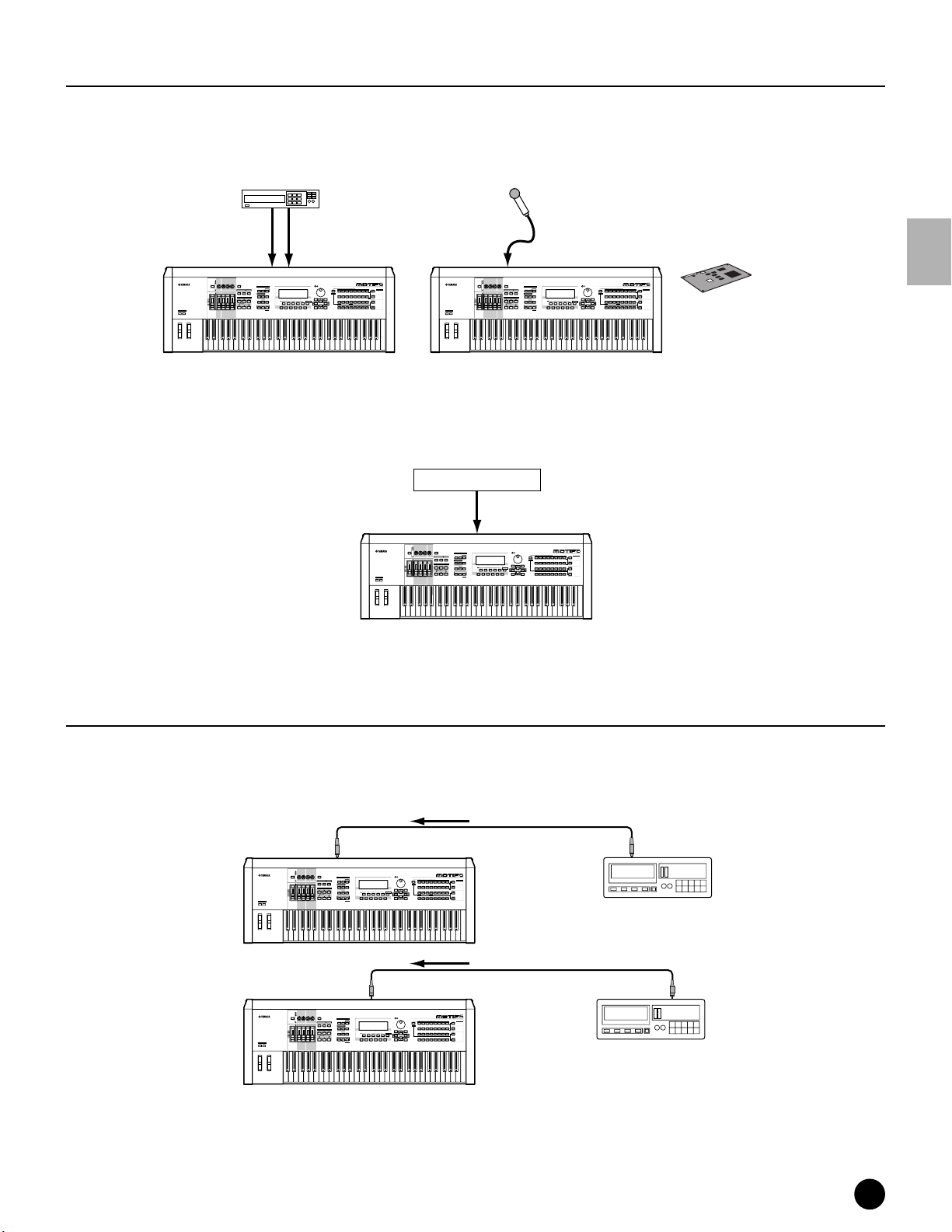
Connections
A/D input
■ Connecting a microphone or other audio equipment (analog input)
You can record or import external sounds or waveform data and use them as instrument sounds (see
“Sampling” on page 58). When recording from an external audio source, connect a microphone or the audio source
to the A/D INPUT jacks.
AD INPUT
REMOTE
CONTROL
ON/OFF
VOICE PERFORM MASTER
ARPEGGIO
EFFECT BYPASS
SYSTEM
ON/OFF
INSERTION
SEQUENCER
SONG
SEQ
TRANSPORT
INTEGRATED
SAMPLING
2
LOCATE
1
REC
EDIT
COMPARE
Mic
(MONO)
MODE
PATTERN FILE
UTILITY
MIXING
SONG SCENE
SF 1SF 2SF 3SF 4SF 5
STORE
JOB
F1 F2 F3 F4 F6F5
SCENE STORE
SET LOCATE
Apply effects to the microphone
sound by using the Vocal Harmony
Plug-in board (PLG100-VH).
MUSIC
SYNTHESIZER
PRODUCTION
Sequencer
Sampling
Integrated
Real-timeExternalControl
Surface
Modular
Synthesis
Plug-in
System
SLOT 1 SLOT 2 SLOT 3
CATEGORY
PRE 2
PRE 1
PRE 3
PLG 3
USER PLG 1
PLG 2
DRUM KITS
GM
SEARCH
BANK
GUITAR/
KEYBOARD
BRASS
A. PIANO
STRINGS
REED/PIPE
ORGAN
FAVORITES
BASS
PLUCKED
COMMON
D
SECTION
B
E
A
C
FGH
DEC/NO INC/YES
INFORMATION
ENTER
EXIT
EXECUTE
GROUP
DRUM/
SYN COMPCHROMATIC
SE
SYN LEAD SYN PAD/
MUSICAL FX COMBI
PERCUSSION
PERCUSSION
CHOIR
TRACK
1
34567
2
8
SELECT
ELEMENT/PERF.PART/ZONE
NUMBER
11
12
10
131416
9
MUTE
15
SOLO
Audio Device (Stereo)
RL
AD INPUT
PAN
CHORUS
REVERB
TEMPO
ATTACK RELEASECUTOFF
RESONANCE
KNOB
REMOTE
ASSIGN A ASSIGN B ASSIGN 1 ASSIGN 2
CONTROL
CONTROL
FUNCTION
ON/OFF
KN 1 KN 2 KN 3 KN 4
MEQ LOW
MEQ HI MIDMEQLOWMID MEQ HIGH
ARPEGGIO
EFFECT BYPASS
SYSTEM
ON/OFF
INSERTION
MASTER
VOLUME 1VOLUME 2 VOLUME 3 VOLUME 4
VOLUME
SEQ
TRANSPORT
2
LOCATE
1
REC
CS 1 CS 2 CS 3 CS 4
OCTAVE
UP
DOWN
ZONE 1 ZONE 2 ZONE 3 ZONE 4
Sampling
R
L
PAN
CHORUS
REVERB
TEMPO
ATTACK RELEASECUTOFF
RESONANCE
KNOB
MUSIC
SYNTHESIZER
PRODUCTION
Sequencer
Sampling
Integrated
Real-timeExternalControl
Surface
Modular
Synthesis
Plug-in
System
MODE
VOICE PERFORM MASTER
SEQUENCER
SONG
PATTERN FILE
INTEGRATED
SAMPLING
UTILITY
MIXING
SONG SCENE
INFORMATION
SF 1SF 2SF 3SF 4SF 5
EDIT
STORE
JOB
F1 F2 F3 F4 F6F5
SCENE STORE
COMPARE
SET LOCATE
DEC/NO INC/YES
SLOT 1 SLOT 2 SLOT 3
CATEGORY
PRE 2
PRE 1
PRE 3
PLG 3
USER PLG 1
PLG 2
DRUM KITS
GM
SEARCH
BANK
GUITAR/
KEYBOARD
BRASS
A. PIANO
STRINGS
REED/PIPE
ORGAN
FAVORITES
BASS
PLUCKED
COMMON
D
SECTION
B
E
A
C
FGH
GROUP
DRUM/
SYN COMPCHROMATIC
SE
SYN LEAD SYN PAD/
MUSICAL FX COMBI
PERCUSSION
PERCUSSION
CHOIR
TRACK
1
34567
2
8
SELECT
ELEMENT/PERF.PART/ZONE
NUMBER
11
12
10
131416
9
ENTER
EXIT
EXECUTE
MUTE
15
SOLO
ASSIGN A ASSIGN B ASSIGN 1 ASSIGN 2
CONTROL
FUNCTION
KN 1 KN 2 KN 3 KN 4
MEQ LOW
MEQ HI MIDMEQLOWMID MEQ HIGH
MASTER
VOLUME 1VOLUME 2 VOLUME 3 VOLUME 4
VOLUME
CS 1 CS 2 CS 3 CS 4
OCTAVE
UP
DOWN
ZONE 1 ZONE 2 ZONE 3 ZONE 4
MOTIF MOTIF
n After the above connections are complete, you are ready to set up for recording. When starting a recording, you may need to adjust the
input gain of the audio source using the GAIN knob. (page 18).
■ Connecting to mLAN-compatible audio equipment
mLAN audio device
Sampling
mLAN jacks
PAN
CHORUS
REVERB
TEMPO
ATTACK RELEASECUTOFF
RESONANCE
KNOB
REMOTE
ASSIGN A ASSIGN B ASSIGN 1 ASSIGN 2
CONTROL
CONTROL
FUNCTION
ON/OFF
MODE
KN 1 KN 2 KN 3 KN 4
VOICE PERFORM MASTER
MEQ LOW
MEQ HI MIDMEQLOWMID MEQ HIGH
ARPEGGIO
EFFECT BYPASS
SYSTEM
ON/OFF
INSERTION
MASTER
VOLUME 1VOLUME 2 VOLUME 3 VOLUME 4
VOLUME
OCTAVE
UP
DOWN
CS 1 CS 2 CS 3 CS 4
ZONE 1 ZONE 2 ZONE 3 ZONE 4
SEQUENCER
SONG
PATTERN FILE
SEQ
TRANSPORT
INTEGRATED
SAMPLING
UTILITY
MIXING
SONG SCENE
SF 1SF 2SF 3SF 4SF 5
2
LOCATE
1
REC
EDIT
STORE
JOB
F1 F2 F3 F4 F6F5
SCENE STORE
COMPARE
SET LOCATE
MUSIC
SYNTHESIZER
PRODUCTION
Sequencer
Sampling
Integrated
Real-timeExternalControl
Surface
Modular
Synthesis
Plug-in
System
SLOT 1 SLOT 2 SLOT 3
CATEGORY
PRE 2
PRE 1
PRE 3
PLG 3
PLG 2
DRUM KITS
USER PLG 1
GM
SEARCH
BANK
GUITAR/
KEYBOARD
BRASS
STRINGS
A. PIANO
REED/PIPE
ORGAN
FAVORITES
BASS
PLUCKED
COMMON
D
B
E
SECTION
A
C
FGH
DEC/NO INC/YES
INFORMATION
ENTER
EXIT
EXECUTE
GROUP
DRUM/
SYN COMPCHROMATIC
SE
SYN LEAD SYN PAD/
MUSICAL FX COMBI
PERCUSSION
PERCUSSION
CHOIR
TRACK
1
34567
2
8
SELECT
ELEMENT/PERF.PART/ZONE
NUMBER
11
12
10
131416
9
MUTE
15
SOLO
MOTIF
n The sound via either of the mLAN jacks and the A/D INPUT jacks can be input. You can set which jacks are used in the Utility
mode (page 252).
Digital input (when the optional AIEB2 has been installed)
By installing the optional AIEB2 I/O expansion board, you can directly record digital audio from digital sources —
such as a CD player or DAT deck. For maximum compatibility and flexibility, the AIEB2 board includes two
different input types: OPTICAL (optical fiber) and DIGITAL (coaxial cable).
OCTAVE
UP
DOWN
OPTICAL
INPUT
PAN
REVERB
RESONANCE
KNOB
ASSIGN A ASSIGN B ASSIGN 1 ASSIGN 2
CONTROL
FUNCTION
KN 1 KN 2 KN 3 KN 4
MEQ LOW
MASTER
VOLUME 1VOLUME 2 VOLUME 3 VOLUME 4
VOLUME
CS 1 CS 2 CS 3 CS 4
ZONE 1 ZONE 2 ZONE 3 ZONE 4
Sampling
CHORUS
TEMPO
ATTACK RELEASECUTOFF
REMOTE
CONTROL
ON/OFF
MODE
VOICE PERFORM MASTER
MEQ HI MIDMEQLOWMID MEQ HIGH
ARPEGGIO
EFFECT BYPASS
SYSTEM
ON/OFF
INSERTION
SEQUENCER
SONG
PATTERN FILE
SEQ
TRANSPORT
INTEGRATED
SAMPLING
UTILITY
MIXING
SONG SCENE
SF 1SF 2SF 3SF 4SF 5
2
LOCATE
1
REC
EDIT
STORE
JOB
F1 F2 F3 F4 F6F5
SCENE STORE
COMPARE
SET LOCATE
MUSIC
SYNTHESIZER
PRODUCTION
Sequencer
Sampling
Integrated
Real-timeExternalControl
Surface
Modular
Synthesis
Plug-in
System
SLOT 1 SLOT 2 SLOT 3
CATEGORY
PRE 2
PRE 1
PRE 3
PLG 3
PLG 2
DRUM KITS
USER PLG 1
GM
SEARCH
BANK
GUITAR/
BRASS
KEYBOARD
STRINGS
A. PIANO
REED/PIPE
ORGAN
FAVORITES
BASS
PLUCKED
COMMON
D
B
SECTION
E
A
C
FGH
DEC/NO INC/YES
INFORMATION
ENTER
EXIT
EXECUTE
GROUP
DRUM/
SYN COMPCHROMATIC
SE
SYN LEAD SYN PAD/
MUSICAL FX COMBI
PERCUSSION
PERCUSSION
CHOIR
TRACK
1
34567
2
8
SELECT
ELEMENT/PERF.PART/ZONE
NUMBER
11
12
10
131416
9
MUTE
15
SOLO
Optical cable
OPTICAL
OUTPUT
DAT
DAT or CD recorder
Setting Up
MOTIF
DIGITAL
INPUT
PAN
CHORUS
REVERB
TEMPO
ATTACK RELEASECUTOFF
RESONANCE
KNOB
REMOTE
ASSIGN A ASSIGN B ASSIGN 1 ASSIGN 2
CONTROL
CONTROL
FUNCTION
ON/OFF
MODE
KN 1 KN 2 KN 3 KN 4
VOICE PERFORM MASTER
MEQ LOW
MEQ HI MIDMEQLOWMID MEQ HIGH
ARPEGGIO
EFFECT BYPASS
SYSTEM
ON/OFF
INSERTION
MASTER
VOLUME 1VOLUME 2 VOLUME 3 VOLUME 4
VOLUME
SEQUENCER
SONG
PATTERN FILE
SEQ
TRANSPORT
INTEGRATED
SAMPLING
UTILITY
MIXING
SONG SCENE
INFORMATION
SF 1SF 2SF 3SF 4SF 5
2
LOCATE
1
REC
EDIT
STORE
JOB
F1 F2 F3 F4 F6F5
SCENE STORE
COMPARE
CS 1 CS 2 CS 3 CS 4
OCTAVE
UP
DOWN
ZONE 1 ZONE 2 ZONE 3 ZONE 4
SET LOCATE
DEC/NO INC/YES
EXIT
Sampling
MUSIC
SYNTHESIZER
PRODUCTION
Sequencer
Sampling
Integrated
Real-timeExternalControl
Surface
Modular
Synthesis
Plug-in
System
SLOT 1 SLOT 2 SLOT 3
CATEGORY
PRE 2
PRE 1
PRE 3
PLG 3
USER PLG 1
PLG 2
DRUM KITS
GM
SEARCH
BANK
GUITAR/
KEYBOARD
BRASS
STRINGS
A. PIANO
REED/PIPE
ORGAN
FAVORITES
BASS
PLUCKED
COMMON
D
SECTION
B
E
A
C
FGH
GROUP
DRUM/
SYN COMPCHROMATIC
SE
SYN LEAD SYN PAD/
MUSICAL FX COMBI
PERCUSSION
PERCUSSION
CHOIR
TRACK
1
34567
2
8
SELECT
ELEMENT/PERF.PART/ZONE
NUMBER
11
12
10
131416
9
ENTER
EXECUTE
MUTE
15
SOLO
Coaxial cable
DIGITAL
OUTPUT
DAT
DAT or CD recorder
MOTIF
n Either one of the connectors (OPTICAL or DIGITAL) can be used; however, both cannot be used at the same time. Select which
connector is used for digital input in the Utility mode. See page 249.
MOTIF Setting Up
23
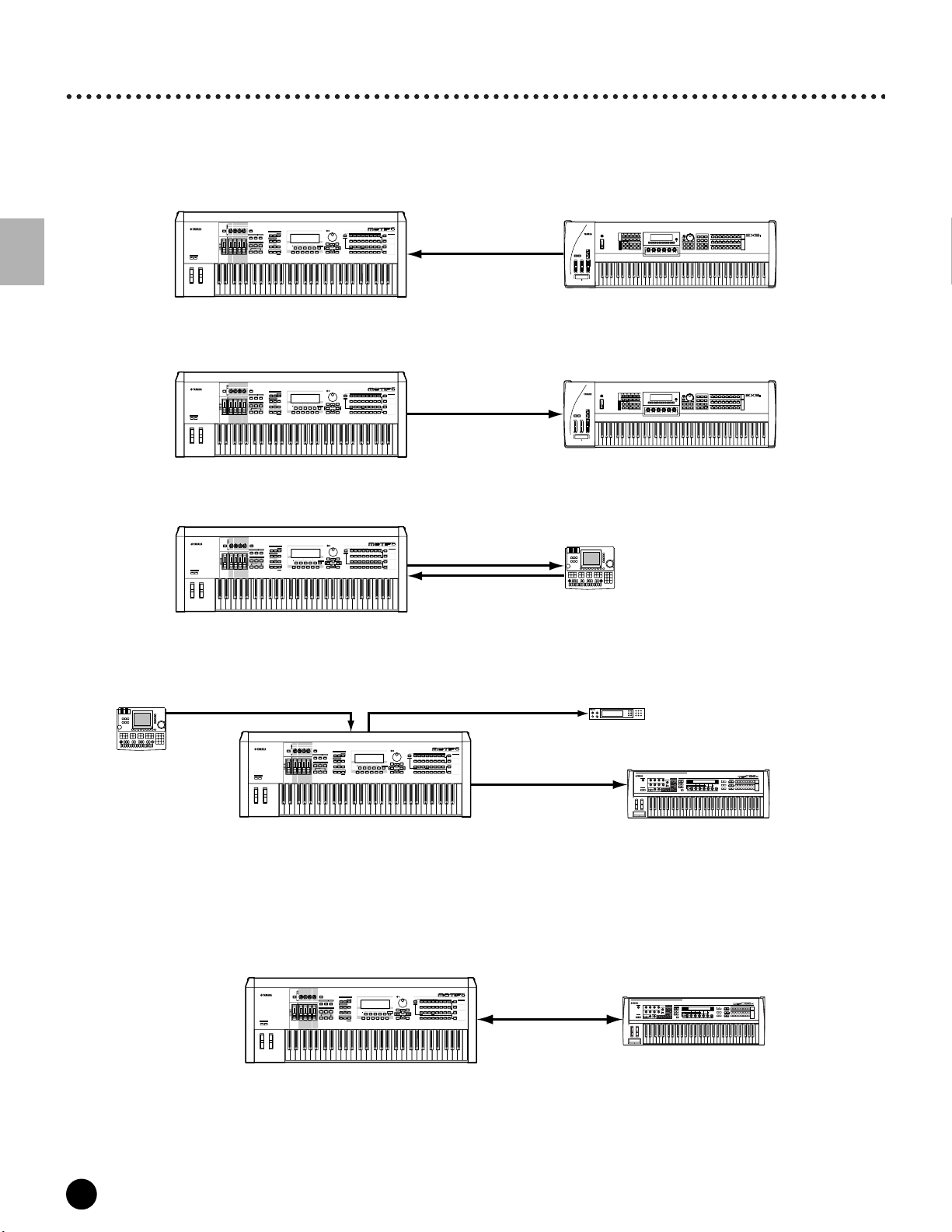
Connections
Connecting External MIDI Equipment
Using a standard MIDI cable (available separately), you can connect an external MIDI device, and control it from the
MOTIF. Likewise, you can use an external MIDI device (such as a keyboard or sequencer) to control the sounds on
the MOTIF. Below are several different MIDI connection examples; use the one most similar to your intended setup.
■ Controlling from an external MIDI keyboard
PAN
CHORUS
REVERB
TEMPO
ATTACK RELEASECUTOFF
RESONANCE
KNOB
REMOTE
ASSIGN A ASSIGN B ASSIGN 1 ASSIGN 2
CONTROL
CONTROL
FUNCTION
ON/OFF
MODE
KN 1 KN 2 KN 3 KN 4
VOICE PERFORM MASTER
MEQ LOW
MEQ HI MIDMEQLOWMID MEQ HIGH
ARPEGGIO
EFFECT BYPASS
SYSTEM
ON/OFF
INSERTION
MASTER
VOLUME 1VOLUME 2 VOLUME 3 VOLUME 4
VOLUME
OCTAVE
UP
DOWN
CS 1 CS 2 CS 3 CS 4
ZONE 1 ZONE 2 ZONE 3 ZONE 4
SEQUENCER
SONG
PATTERN FILE
SEQ
TRANSPORT
INTEGRATED
SAMPLING
UTILITY
MIXING
SONG SCENE
SF 1SF 2SF 3SF 4SF 5
2
LOCATE
1
REC
EDIT
STORE
JOB
F1 F2 F3 F4 F6F5
SCENE STORE
COMPARE
SET LOCATE
MUSIC
SYNTHESIZER
PRODUCTION
Sequencer
Sampling
Integrated
Real-timeExternalControl
Surface
Modular
Synthesis
Plug-in
System
SLOT 1 SLOT 2 SLOT 3
CATEGORY
PRE 2
PRE 1
PRE 3
PLG 3
PLG 2
DRUM KITS
USER PLG 1
GM
SEARCH
BANK
GUITAR/
BRASS
KEYBOARD
A. PIANO
STRINGS
REED/PIPE
ORGAN
FAVORITES
BASS
PLUCKED
COMMON
D
B
E
SECTION
A
C
FGH
DEC/NO INC/YES
INFORMATION
ENTER
EXIT
EXECUTE
GROUP
DRUM/
SYN COMPCHROMATIC
SE
SYN LEAD SYN PAD/
MUSICAL FX COMBI
PERCUSSION
PERCUSSION
CHOIR
TRACK
1
34567
2
8
SELECT
ELEMENT/PERF.PART/ZONE
11
12
10
131416
9
MIDI IN
NUMBER
MUTE
15
SOLO
MIDI OUT
MUSIC SYNTHESIZER
REALTIME CONTROL
EXTENDED SYNTHESIS
Setting Up
MOTIF
■ Controlling an external MIDI keyboard
PAN
CHORUS
REVERB
TEMPO
ATTACK RELEASECUTOFF
RESONANCE
KNOB
REMOTE
ASSIGN A ASSIGN B ASSIGN 1 ASSIGN 2
CONTROL
CONTROL
FUNCTION
ON/OFF
MODE
KN 1 KN 2 KN 3 KN 4
VOICE PERFORM MASTER
MEQ LOW
MEQ HI MIDMEQLOWMID MEQ HIGH
ARPEGGIO
EFFECT BYPASS
SYSTEM
ON/OFF
INSERTION
MASTER
VOLUME 1VOLUME 2 VOLUME 3 VOLUME 4
VOLUME
OCTAVE
UP
DOWN
CS 1 CS 2 CS 3 CS 4
ZONE 1 ZONE 2 ZONE 3 ZONE 4
SEQUENCER
SONG
PATTERN FILE
SEQ
TRANSPORT
INTEGRATED
SAMPLING
UTILITY
MIXING
SONG SCENE
SF 1SF 2SF 3SF 4SF 5
2
LOCATE
1
REC
EDIT
STORE
JOB
F1 F2 F3 F4 F6F5
SCENE STORE
COMPARE
SET LOCATE
MUSIC
SYNTHESIZER
PRODUCTION
Sequencer
Sampling
Integrated
Real-timeExternalControl
Surface
Modular
Synthesis
Plug-in
System
SLOT 1 SLOT 2 SLOT 3
CATEGORY
PRE 2
PRE 1
PRE 3
PLG 3
USER PLG 1
PLG 2
DRUM KITS
GM
SEARCH
BANK
GUITAR/
KEYBOARD
BRASS
A. PIANO
STRINGS
REED/PIPE
ORGAN
FAVORITES
BASS
PLUCKED
COMMON
D
SECTION
E
B
A
C
FGH
DEC/NO INC/YES
INFORMATION
ENTER
EXIT
EXECUTE
GROUP
DRUM/
SYN COMPCHROMATIC
SE
SYN LEAD SYN PAD/
MUSICAL FX COMBI
PERCUSSION
PERCUSSION
CHOIR
TRACK
1
34567
2
8
SELECT
131416
MIDI OUT
NUMBER
MUTE
15
SOLO
ELEMENT/PERF.PART/ZONE
11
12
10
9
MIDI IN
MOTIF
■ Recording and playback using an external MIDI sequencer
PAN
CHORUS
REVERB
TEMPO
ATTACK RELEASECUTOFF
RESONANCE
KNOB
REMOTE
ASSIGN A ASSIGN B ASSIGN 1 ASSIGN 2
CONTROL
CONTROL
FUNCTION
ON/OFF
MODE
KN 1 KN 2 KN 3 KN 4
VOICE PERFORM MASTER
MEQ LOW
MEQ HI MIDMEQLOWMID MEQ HIGH
ARPEGGIO
EFFECT BYPASS
SYSTEM
ON/OFF
INSERTION
MASTER
VOLUME 1VOLUME 2 VOLUME 3 VOLUME 4
VOLUME
OCTAVE
UP
DOWN
CS 1 CS 2 CS 3 CS 4
ZONE 1 ZONE 2 ZONE 3 ZONE 4
SEQUENCER
SONG
PATTERN FILE
SEQ
TRANSPORT
INTEGRATED
SAMPLING
UTILITY
MIXING
SONG SCENE
SF 1SF 2SF 3SF 4SF 5
2
LOCATE
1
REC
EDIT
STORE
JOB
F1 F2 F3 F4 F6F5
SCENE STORE
COMPARE
SET LOCATE
MUSIC
SYNTHESIZER
PRODUCTION
Sequencer
Sampling
Integrated
Real-timeExternalControl
Surface
Modular
Synthesis
Plug-in
System
SLOT 1 SLOT 2 SLOT 3
CATEGORY
PRE 2
PRE 1
PRE 3
PLG 3
PLG 2
DRUM KITS
USER PLG 1
GM
SEARCH
BANK
GUITAR/
KEYBOARD
BRASS
STRINGS
A. PIANO
REED/PIPE
ORGAN
FAVORITES
BASS
PLUCKED
COMMON
D
B
E
SECTION
A
C
FGH
DEC/NO INC/YES
INFORMATION
ENTER
EXIT
EXECUTE
GROUP
DRUM/
SYN COMPCHROMATIC
SYN LEAD SYN PAD/
PERCUSSION
PERCUSSION
CHOIR
1
34567
2
ELEMENT/PERF.PART/ZONE
11
12
10
9
MIDI OUT
SE
MUSICAL FX COMBI
TRACK
8
SELECT
NUMBER
131416
MUTE
15
SOLO
MIDI IN
MIDI IN
MIDI OUT
MOTIF
■ Controlling another MIDI device via MIDI THRU
External MIDI sequencer
MIDI OUT
MIDI THRUMIDI IN
PAN
CHORUS
REVERB
TEMPO
ATTACK RELEASECUTOFF
RESONANCE
KNOB
REMOTE
ASSIGN A ASSIGN B ASSIGN 1 ASSIGN 2
CONTROL
CONTROL
FUNCTION
ON/OFF
MODE
KN 1 KN 2 KN 3 KN 4
VOICE PERFORM MASTER
MEQ LOW
MEQ HI MIDMEQLOWMID MEQ HIGH
ARPEGGIO
EFFECT BYPASS
SYSTEM
ON/OFF
INSERTION
MASTER
VOLUME 1VOLUME 2 VOLUME 3 VOLUME 4
VOLUME
OCTAVE
UP
DOWN
CS 1 CS 2 CS 3 CS 4
ZONE 1 ZONE 2 ZONE 3 ZONE 4
SEQUENCER
SONG
PATTERN FILE
SEQ
TRANSPORT
INTEGRATED
SAMPLING
UTILITY
MIXING
SONG SCENE
SF 1SF 2SF 3SF 4SF 5
2
LOCATE
1
REC
EDIT
STORE
JOB
F1 F2 F3 F4 F6F5
SCENE STORE
COMPARE
SET LOCATE
MUSIC
SYNTHESIZER
PRODUCTION
Sequencer
Sampling
Integrated
Real-timeExternalControl
Surface
Modular
Synthesis
Plug-in
System
SLOT 1 SLOT 2 SLOT 3
CATEGORY
PRE 2
PRE 1
PRE 3
PLG 3
PLG 2
DRUM KITS
USER PLG 1
GM
SEARCH
BANK
GUITAR/
KEYBOARD
BRASS
A. PIANO
STRINGS
REED/PIPE
ORGAN
FAVORITES
BASS
PLUCKED
COMMON
D
B
E
SECTION
A
C
FGH
DEC/NO INC/YES
INFORMATION
ENTER
EXIT
EXECUTE
GROUP
DRUM/
SYN COMPCHROMATIC
SE
SYN LEAD SYN PAD/
MUSICAL FX COMBI
PERCUSSION
PERCUSSION
CHOIR
TRACK
1
34567
2
8
SELECT
ELEMENT/PERF.PART/ZONE
NUMBER
11
12
10
131416
9
MUTE
15
SOLO
MIDI OUT
MIDI IN
Extrnal MIDI keyboard or synthesizer
External MIDI keyboard or synthesizer
External MIDI sequencer
External MIDI synthesizer 1
MIDI IN
MUSIC SYNTHESIZER
REALTIME CONTROL
EXTENDED SYNTHESIS
C
MOTIF
External MIDI synthesizer 2
In the above setup, Synthesizer 2 can be played from the MOTIF (via MIDI OUT), while the external sequencer
plays Synthesizer 1 (via MIDI THRU).
n The MIDI cable should be no greater than 15 meters in length, and there should be no more than three devices in a MIDI chain
(chained in series via each unit’s MIDI THRU). To connect more units, use a MIDI Thru Box for parallel connections. You may
encounter errors if the MIDI cables are too long or if too many devices are chained together via their MIDI THRU connectors.
■ Using an mLAN interface (when an optional mLAN8E has been installed)
PAN
CHORUS
REVERB
TEMPO
ATTACK RELEASECUTOFF
RESONANCE
KNOB
REMOTE
ASSIGN A ASSIGN B ASSIGN 1 ASSIGN 2
CONTROL
CONTROL
FUNCTION
ON/OFF
MODE
KN 1 KN 2 KN 3 KN 4
VOICE PERFORM MASTER
MEQ LOW
MEQ HI MIDMEQLOWMID MEQ HIGH
ARPEGGIO
EFFECT BYPASS
SYSTEM
ON/OFF
INSERTION
MASTER
VOLUME 1VOLUME 2 VOLUME 3 VOLUME 4
VOLUME
OCTAVE
UP
DOWN
CS 1 CS 2 CS 3 CS 4
ZONE 1 ZONE 2 ZONE 3 ZONE 4
SEQUENCER
SONG
PATTERN FILE
SEQ
TRANSPORT
INTEGRATED
SAMPLING
UTILITY
MIXING
SONG SCENE
SF 1SF 2SF 3SF 4SF 5
2
LOCATE
1
REC
EDIT
STORE
JOB
F1 F2 F3 F4 F6F5
SCENE STORE
COMPARE
SET LOCATE
MOTIF
n Any one of the these interfaces can be used for MIDI data transmission/reception: the MIDI connectors, the mLAN terminal
connector, or the USB connector. However, they cannot be used at the same time. Select which connector is used for MIDI data
transfer in the Utility mode. See page 259.
24
MOTIF Setting Up
MUSIC
SYNTHESIZER
PRODUCTION
Sequencer
Sampling
Integrated
Real-timeExternalControl
Surface
Modular
Synthesis
Plug-in
System
SLOT 1 SLOT 2 SLOT 3
CATEGORY
PRE 2
PRE 1
PRE 3
PLG 3
PLG 2
DRUM KITS
USER PLG 1
GM
SEARCH
BANK
GUITAR/
BRASS
KEYBOARD
STRINGS
A. PIANO
REED/PIPE
ORGAN
FAVORITES
BASS
PLUCKED
COMMON
D
B
E
SECTION
A
C
FGH
DEC/NO INC/YES
INFORMATION
ENTER
EXIT
EXECUTE
GROUP
DRUM/
SE
SYN COMPCHROMATIC
MUSICAL FX COMBI
SYN LEAD SYN PAD/
PERCUSSION
PERCUSSION
CHOIR
TRACK
1
34567
2
8
SELECT
ELEMENT/PERF.PART/ZONE
NUMBER
11
12
10
131416
9
MUTE
15
SOLO
IEEE1394 cable
C
Transmit & Receive
mLan keyboard
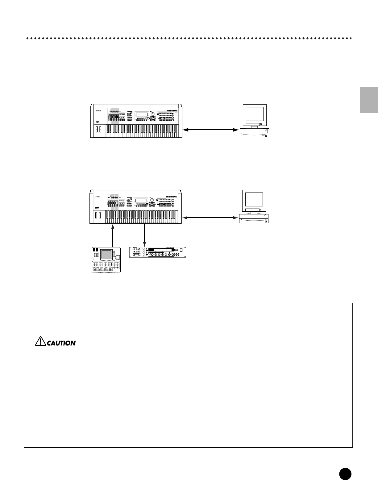
Connections
Connecting to a Personal Computer
By connecting a computer, you can transfer data between the MOTIF and the computer via MIDI, and use the
computer to control, edit and organize data on the MOTIF. For example, you can use the included Voice Editor
program to edit the MOTIF’s voices. There’s also a special File Utility program that lets you use your computer to
manage files in the Memory Card inserted in the MOTIF’s CARD slot or files in the SCSI device connected to the
MOTIF.
■ Using an USB interface
PAN
CHORUS
REVERB
TEMPO
ATTACK RELEASECUTOFF
RESONANCE
KNOB
REMOTE
ASSIGN A ASSIGN B ASSIGN 1 ASSIGN 2
CONTROL
CONTROL
FUNCTION
ON/OFF
MODE
KN 1 KN 2 KN 3 KN 4
VOICE PERFORM MASTER
MEQ LOW
MEQ HI MIDMEQLOWMID MEQ HIGH
ARPEGGIO
EFFECT BYPASS
SYSTEM
ON/OFF
INSERTION
MASTER
VOLUME 1VOLUME 2 VOLUME 3 VOLUME 4
VOLUME
OCTAVE
UP
DOWN
CS 1 CS 2 CS 3 CS 4
ZONE 1 ZONE 2 ZONE 3 ZONE 4
SEQUENCER
SONG
PATTERN FILE
SEQ
TRANSPORT
INTEGRATED
SAMPLING
UTILITY
MIXING
SONG SCENE
SF 1SF 2SF 3SF 4SF 5
2
LOCATE
1
REC
EDIT
STORE
JOB
F1 F2 F3 F4 F6F5
SCENE STORE
COMPARE
SET LOCATE
MUSIC
SYNTHESIZER
PRODUCTION
Sequencer
Sampling
Integrated
Real-timeExternalControl
Surface
Modular
Synthesis
Plug-in
System
SLOT 1 SLOT 2 SLOT 3
CATEGORY
PRE 2
PRE 1
PRE 3
PLG 3
USER PLG 1
PLG 2
DRUM KITS
GM
SEARCH
BANK
GUITAR/
KEYBOARD
BRASS
A. PIANO
STRINGS
REED/PIPE
ORGAN
FAVORITES
BASS
PLUCKED
COMMON
D
SECTION
B
E
A
C
FGH
DEC/NO INC/YES
INFORMATION
ENTER
EXIT
EXECUTE
GROUP
DRUM/
SYN COMPCHROMATIC
SE
SYN LEAD SYN PAD/
MUSICAL FX COMBI
PERCUSSION
PERCUSSION
CHOIR
TRACK
1
34567
2
8
SELECT
ELEMENT/PERF.PART/ZONE
NUMBER
11
12
131416
10
9
MUTE
15
SOLO
USB cable
MOTIF
Computer with a USB Interface
n If you are using the Remote Control function to control operations on a computer sequencer, we recommend making connections
with a USB cable.
n The USB connection can only be used for transfer of MIDI data. No audio data can be transfered via USB.
MOTIF
PAN
CHORUS
REVERB
TEMPO
ATTACK RELEASECUTOFF
RESONANCE
KNOB
REMOTE
ASSIGN A ASSIGN B ASSIGN 1 ASSIGN 2
CONTROL
CONTROL
FUNCTION
ON/OFF
KN 1 KN 2 KN 3 KN 4
MEQ LOW
MEQ HI MIDMEQLOWMID MEQ HIGH
ARPEGGIO
EFFECT BYPASS
SYSTEM
ON/OFF
INSERTION
MASTER
VOLUME 1VOLUME 2 VOLUME 3 VOLUME 4
VOLUME
SEQ
TRANSPORT
2
LOCATE
1
REC
CS 1 CS 2 CS 3 CS 4
OCTAVE
UP
DOWN
ZONE 1 ZONE 2 ZONE 3 ZONE 4
MIDI IN
MIDI cable
MIDI OUT
External MIDI sequencer
MODE
VOICE PERFORM MASTER
SEQUENCER
SONG
PATTERN FILE
INTEGRATED
SAMPLING
UTILITY
MIXING
SONG SCENE
SF 1SF 2SF 3SF 4SF 5
EDIT
STORE
JOB
F1 F2 F3 F4 F6F5
SCENE STORE
COMPARE
SET LOCATE
External MIDI synthesizer
DEC/NO INC/YES
INFORMATION
EXIT
MIDI OUT
MIDI IN
MUSIC
SYNTHESIZER
PRODUCTION
Sequencer
Sampling
Integrated
Real-timeExternalControl
Surface
Modular
Synthesis
Plug-in
System
SLOT 1 SLOT 2 SLOT 3
CATEGORY
PRE 2
PRE 1
PRE 3
PLG 3
PLG 2
DRUM KITS
USER PLG 1
GM
SEARCH
BANK
GUITAR/
KEYBOARD
BRASS
A. PIANO
STRINGS
REED/PIPE
ORGAN
FAVORITES
BASS
PLUCKED
COMMON
D
SECTION
E
B
A
C
FGH
GROUP
DRUM/
SYN COMPCHROMATIC
SE
SYN LEAD SYN PAD/
MUSICAL FX COMBI
PERCUSSION
PERCUSSION
CHOIR
TRACK
1
34567
2
8
SELECT
ELEMENT/PERF.PART/ZONE
NUMBER
11
12
10
131416
9
ENTER
EXECUTE
MUTE
15
SOLO
USB cable
transmission & receive
Computer with a USB interface
n When you connect your computer to the MOTIF as illustrated above, you will need to select “USB” for MIDI data transmission in
the Utility mode. (page 258)
About the USB connector
USB cables have different connectors on each end: the A type and the B type. When using the USB connection,
connect the A type to your computer and the B type to the MOTIF.
Setting Up
Disconnecting/connecting the USB cable or turning the power off/on may cause the computer operation to hang-up,
or may stop the MOTIF from functioning properly. Be careful NOT to disrupt the USB connection or turn the power
on/off in the following operating conditions.
• While the MOTIF is recognizing the device or while loading the driver.
• While starting or shutting down the operating system.
• While computer operation is suspended (with power management controls such as sleep or hibernation).
• While a MIDI application is starting.
The computer may also hang up and/or the MOTIF’s functions may stop if you do the following:
• Turn the power on/off, or connect/disconnect the cable too often.
• Enter the sleep mode while trasmitting the MIDI data, and resume operation.
• Disconnect/connect the cable while the MOTIF is on.
• Turn the MOTIF on/off, start the computer, or install driver software while a huge amount of data is being transferred.
MOTIF Setting Up
25

Connections
■ Using an IEEE1394 interface (when an optional mLAN8E has been installed)
PAN
CHORUS
REVERB
TEMPO
ATTACK RELEASECUTOFF
RESONANCE
KNOB
REMOTE
ASSIGN A ASSIGN B ASSIGN 1 ASSIGN 2
CONTROL
CONTROL
FUNCTION
ON/OFF
MODE
KN 1 KN 2 KN 3 KN 4
VOICE PERFORM MASTER
MEQ LOW
MEQ HI MIDMEQLOWMID MEQ HIGH
ARPEGGIO
EFFECT BYPASS
SYSTEM
ON/OFF
INSERTION
MASTER
VOLUME 1VOLUME 2 VOLUME 3 VOLUME 4
VOLUME
OCTAVE
UP
DOWN
CS 1 CS 2 CS 3 CS 4
ZONE 1 ZONE 2 ZONE 3 ZONE 4
SEQUENCER
SONG
PATTERN FILE
SEQ
TRANSPORT
INTEGRATED
SAMPLING
UTILITY
MIXING
SONG SCENE
SF 1SF 2SF 3SF 4SF 5
2
LOCATE
1
REC
EDIT
STORE
JOB
F1 F2 F3 F4 F6F5
SCENE STORE
COMPARE
SET LOCATE
MUSIC
SYNTHESIZER
PRODUCTION
Sequencer
Sampling
Integrated
Real-timeExternalControl
Surface
Modular
Synthesis
Plug-in
System
SLOT 1 SLOT 2 SLOT 3
CATEGORY
PRE 2
PRE 1
PRE 3
PLG 3
PLG 2
DRUM KITS
USER PLG 1
GM
SEARCH
BANK
GUITAR/
KEYBOARD
BRASS
STRINGS
A. PIANO
REED/PIPE
ORGAN
FAVORITES
BASS
PLUCKED
COMMON
D
B
E
SECTION
A
C
FGH
DEC/NO INC/YES
INFORMATION
ENTER
EXIT
EXECUTE
GROUP
DRUM/
SYN COMPCHROMATIC
SE
SYN LEAD SYN PAD/
MUSICAL FX COMBI
PERCUSSION
PERCUSSION
CHOIR
TRACK
1
34567
2
8
SELECT
ELEMENT/PERF.PART/ZONE
NUMBER
11
12
10
131416
9
MUTE
15
SOLO
IEEE1394 cable
■ Using a MIDI interface
Setting Up
●Using the computer’s MIDI interface
●Using an external MIDI interface
MOTIF
Computer with a IEEE1394 interface
%$$ 3=
%$$ $! %$$ "
!
"
%
# "
!!
#!
%
$! $! $! $!
!
!
"!$!
!
%
#! #! #!& #!'
$ %%
%(
%($%$%( %$ %($
$
%
!
$!$!
%
"% "%"% &"%'
"%
"
!
& '
)! )! )!& )!'
("!
!
! $
(
!
$!
%$!
"$$
%$*$!
!!
& '
$
+
& ' ,
!
%
%"$
!$)
"$!
123
/0-
$-.
405
263
%.2
70
2-40
&
&
&
"%#$
"
%
!#
"$
#
$!
8$!
$
!
$
"#
%%!
$!
! $!
$!%$!
!
*$
*"
"
"%
!%%$
! !
%"$* %$
"$!
"$!
$
#
&',9
:
%!8)!
!"%
<
&',
;
%"
%$$ "
%$$ $!
%$
/2 >07 %$$ $63
MIDI Interface
MIDI OUT
serial port
MIDI IN
MIDI IN
PAN
CHORUS
REVERB
TEMPO
ATTACK RELEASECUTOFF
RESONANCE
KNOB
REMOTE
ASSIGNA ASSIGNB ASSIGN1 ASSIGN2
CONTROL
CONTROL
FUNCTION
ON/OFF
KN1 KN2 KN3 KN4
MEQLOW
MEQHIMIDMEQLOWMID MEQHI GH
EFFECTBYPASS
SYSTEM
INSERTION
MASTER
VOLUME1 VOLUME2VOLUME 3VOLUME4
VOLUME
SEQ
TRANSPORT
LOCATE
REC
CS1 CS2 CS3 CS4
OCTAVE
UP
DOWN
ZONE1 ZONE2 ZONE3 ZONE4
MIDI OUT
MUSIC
SYNTHESIZER
PRODUCTION
Sequencer
Sampling
Integrated
Real-timeExternalControl
Surface
Modular
Synthesis
Plug-in
System
MODE
VOICE PERFORMMASTER
ARPEGGIO
ON/OFF
SEQUENCER
SONG
PATTERN FILE
INTEGRATED
SAMPLING
UTILITY
MIXING
SONGSCENE
INFORMATION
SF1 SF2 SF3 SF4 SF5
2
1
EDIT
STORE
JOB
F1 F2 F3 F4 F6F5
SCENESTORE
COMPARE
SETLOCATE
DEC/NO INC/YES
EXIT
SLOT1 SLOT2 SLOT3
CATEGORY
PRE2
PRE1
PRE3
PLG3
USER PLG1
PLG2
DRUMKITS
GM
SEARCH
BANK
GUITAR/
KEYBOARD
BRASS
STRINGS
A.PIANO
REED/PIPE
ORGAN
FAVORITES
BASS
PLUCKED
COMMON
D
B
E
SECTION
A
C
FGH
GROUP
DRUM/
SE
SYNCOMPCHROMATIC
MUSICALFX COMBI
SYNLEAD SYNPAD/
PERCUSSION
PERCUSSION
CHOIR
TRACK
1
34567
2
8
SELECT
ELEMENT/PERF.PART/ZONE
NUMBER
11
12
10
131416
9
ENTER
EXECUTE
MUTE
15
SOLO
(modem or printerport)
or USB port
MOTIF
Computer
n Please use the appropriate MIDI interface for your computer.
n If you are using a computer that has a USB interface, make sure to connect the computer and the MOTIF by USB. (The data
transfer rate is faster than MIDI and you’ll have access to multiple MIDI ports.)
Local On/Off - When Connected to a Computer
When connecting the MOTIF to a computer, the keyboard performance data is generally sent to the computer, and
then returned from the computer to play the tone generator or sound source. If the Local Switch is set to “on,” a
“double” sound may result, since the tone generator is receiving performance data from both the keyboard directly and
the computer. Use the setting suggestions below as a guideline; specific instructions may differ depending on your
computer and the software used.
When MIDI “Echo” is enabled on the software/computer, set the MOTIF Local Switch to “off.”
USB
IN OUT
Tone
Generator
Local Off
Keyborad
MOTIF Local Sw=off
n When transmitting or receiving System Exclusive data (such as with the Bulk Dump function), use the setting example
below, making sure that MIDI “Echo” on the computer software is set to “off.”
Computer with
Application Software
OUT
IN
Echo Back On
26
MOTIF Setting Up

When MIDI “Echo” is disabled on the software/computer, set the MOTIF Local Switch to “on.”
Computer with
OUTUSB
Application Software
Connections
Tone
Generator
MOTIF Local Sw=on
Local On
Keyborad
IN
Echo Back Off
n Although not indicated in the illustration above, the MOTIF actually receives and responds to MIDI data from the
computer application (sequencer), regardless of the Local Sw setting on the MOTIF.
* MIDI “Echo” is a function on sequencers that takes any data received via the MIDI IN and “echoes” it (or sends
it as is) through the MIDI OUT. In some software, this function is also called “MIDI Thru.”
n Refer to the owner's manual of your particular software for specific instructions.
Connecting to an External SCSI Device
Reference (page 262)
This SCSI-2 50-pin connector (D-sub, half-pitch) can be used to connect to an external SCSI data storage device —
allowing you to conveniently save and store large quantities of data. For details about SCSI and connecting SCSI
devices, see page 64.
SYNTHESIZER
Sampling
Synthesis
GM
GUITAR/
PLUCKED
PERCUSSION
12
Sequencer
Surface
Plug-in
System
SLOT 1 SLOT 2 SLOT 3
USER PLG 1
STRINGS
BASS
D
E
FGH
DRUM/
SE
PERCUSSION
131416
CATEGORY
PLG 3
PLG 2
SEARCH
BRASS
REED/PIPE
SECTION
GROUP
MUSICAL FX COMBI
TRACK
8
SELECT
NUMBER
MUTE
15
SOLO
Hard Disk, etc.
BANK
SCSI
PAN
CHORUS
REVERB
TEMPO
ATTACK RELEASECUTOFF
RESONANCE
KNOB
REMOTE
ASSIGN A ASSIGN B ASSIGN 1 ASSIGN 2
CONTROL
CONTROL
FUNCTION
ON/OFF
MODE
KN 1 KN 2 KN 3 KN 4
VOICE PERFORM MASTER
MEQ LOW
MEQ HI MIDMEQLOWMID MEQ HIGH
ARPEGGIO
EFFECT BYPASS
SYSTEM
ON/OFF
INSERTION
MASTER
VOLUME 1VOLUME 2 VOLUME 3 VOLUME 4
VOLUME
SEQUENCER
SONG
PATTERN FILE
SEQ
TRANSPORT
INTEGRATED
SAMPLING
UTILITY
MIXING
SONG SCENE
SF 1SF 2SF 3SF 4SF 5
2
LOCATE
1
REC
EDIT
STORE
JOB
F1 F2 F3 F4 F6F5
SCENE STORE
COMPARE
CS 1 CS 2 CS 3 CS 4
OCTAVE
UP
DOWN
ZONE 1 ZONE 2 ZONE 3 ZONE 4
SET LOCATE
MUSIC
PRODUCTION
Integrated
Real-timeExternalControl
Modular
PRE 2
PRE 1
PRE 3
DRUM KITS
KEYBOARD
A. PIANO
ORGAN
FAVORITES
COMMON
B
A
C
DEC/NO INC/YES
SYN COMPCHROMATIC
SYN LEAD SYN PAD/
CHOIR
1
34567
2
INFORMATION
ELEMENT/PERF.PART/ZONE
11
10
9
ENTER
EXIT
EXECUTE
Setting Up
MOTIF
n The SCSI ID for the MOTIF and for the connected SCSI device are set in the File mode (page 265).
◆ MOTIF-compatible SCSI devices/disks
• Only DOS-format disks can be used by the MOTIF for saving data. Disks formatted by the MOTIF are
formatted using DOS format.
• Disks formatted to DOS format by a personal computer can be used with the MOTIF. However, for best results,
we recommend using disks formatted by the MOTIF.
• When formatted using the MOTIF, disks with a capacity of less than 2GB are formatted using FAT16 format,
and larger disks are formatted using FAT32 format.
• MO disks which can be used with the MOTIF include capacities of 128 MB, 230 MB, and 540 MB. MO disks
with a capacity of 640 MB and above cannot be used.
• The MOTIF can use removable media of capacities of up to 2 GB. Even if larger drives are connected, the
MOTIF can only use a maximum of 2 GB. Furthermore, all removable media are formatted using the FAT16
format, and partitioning is not possible.
• When a 31 GB disk is formatted, four 7.75 GB partitions will be created automatically.
MOTIF Setting Up
27
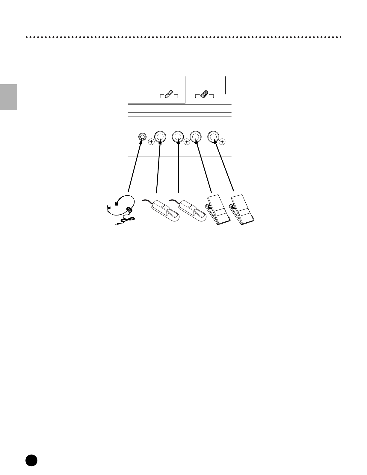
Connections
Connecting Various Controllers
Quick Start Guide (page 48)
The MOTIF features several controller jacks on the rear panel — letting you independently control various aspects
of the sound and a variety of functions with optional controllers.
Setting Up
BC3
BREATH
FOOT
SWITCH
ASSIGNAB LE
FC4
or
FC5
SUSTAIN
FOOT
CONTROLLER
FC4
or
FC5
12
FC7
FC7
28
MOTIF Setting Up

Powering Up
Powering Up
Power-on Procedure
Once you’ve made all the necessary connections between your MOTIF and any other devices, make sure that all
volume settings are turned down all the way to zero. Then turn on the every device in your setup in the order of
MIDI masters (senders), MIDI slaves (receivers), then audio equipment (mixers, amplifiers, speakers, etc.). This
ensures smooth signal flow from the first device to the last (first MIDI, then audio).
When powering down the setup, first turn down the volume for each audio devices, then switch off
each device in the reverse order (first audio devices, then MIDI).
n If the SCSI device is connected to the MOTIF, first turn the SCSI device on and follow the instructions below. When turning the
power off in this case, turn the SCSI device off after all other devices.
When using the MOTIF as MIDI receiver:
213
!
!
#
!
!!
!"
!" ! !"! !"
!
#
!
! !! !
!
$ $ $ $
"
"
!
! %
&
!
!"
!
$
)23)'4)+
,./01'*
'()*+,()-
),05(1.)6()+',07'(+70
3+8,4)
!7-30,+
9'(:);1;
03*51'
9;().
!
!
#
<
#
!!
# #
!
%
%
!#
!!
#
! % !
!#<#$
!
!
Switching the MOTIF On
n Before you switch your MOTIF on or off, first turn down the volume of any audio equipment connected to it.
1 Press the POWER switch.
After a while, the default display appears (as set in the Utility parameter, Power On Mode Display).
Setting Up
POWER
OFF
ON
AC
INLET
MOTIF
2 Raise the sound system volume to a reasonable level.
3 Gradually raise the VOLUME control while playing the keyboard to set the desired listening level.
MOTIF Setting Up
29
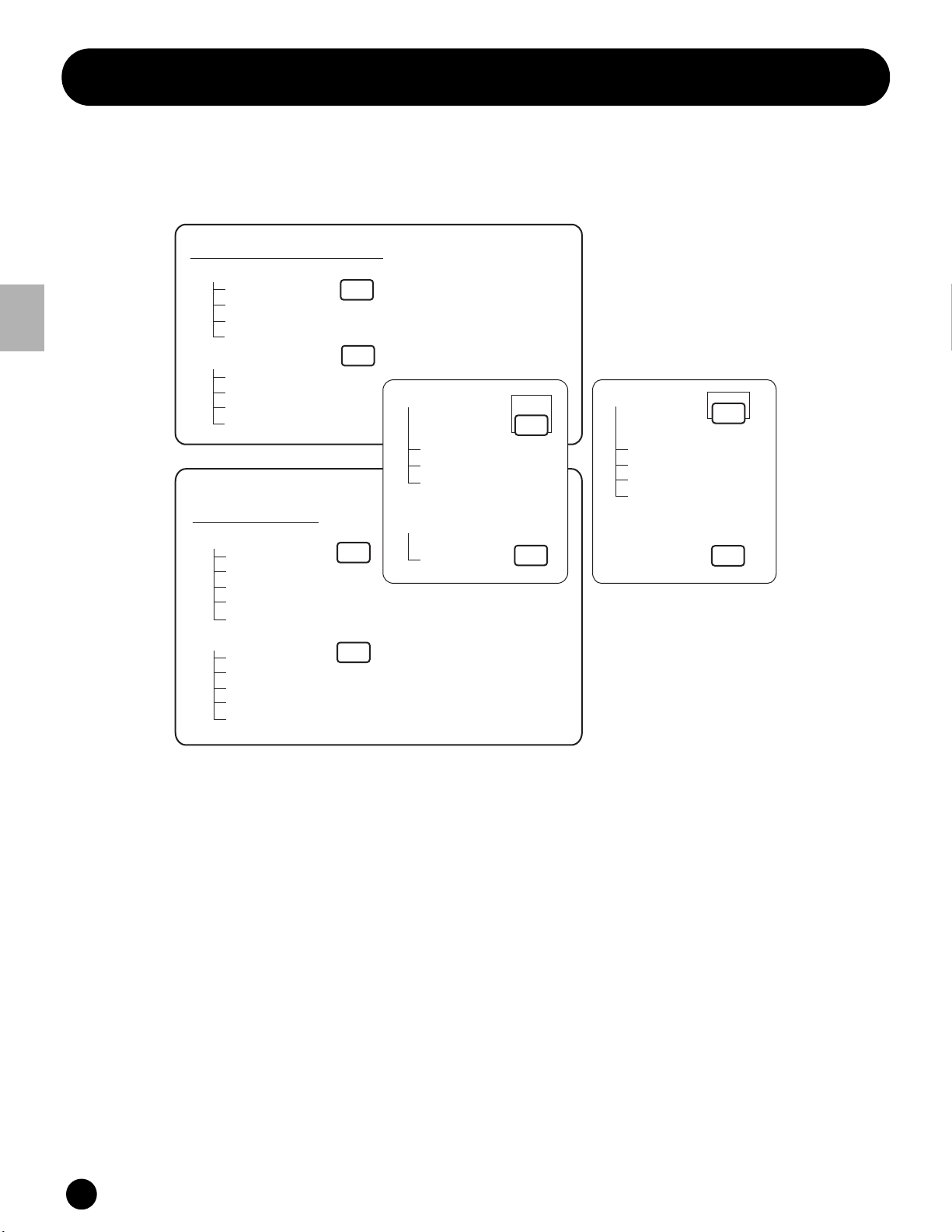
Mode
Basic Structure
Mode
The MOTIF is organized with various modes, each covering a different set of operations and functions.
Keyboard Playback mode
VOICE
PERFORM
SONG
PATTERN
Sampling mode
Sampling Record mode
Sampling Edit mode
Sampling Job mode
Utility mode
Job mode
INTEGRATED
SAMPLING
UTILITY
Master mode
Master Play mode
Master Edit mode
Master Job mode
Master Store mode
File mode
MASTER
Basic Structure
Voice mode
Voice Play mode
Voice Edit mode
Voice Job mode
Voice Store mode
Performance mode
Performance Play mode
Performance Edit mode
Performance Job mode
Performance Store mode
Sequencer mode
(Multi mode)
Song mode
Song Play mode
Song Record mode
Song Edit mode
Song Job mode
Song Mixing mode
Pattern mode
Pattern Play mode
Pattern Record mode
Pattern Edit mode
Pattern Job mode
Pattern Mixing mode
FILE
■ Voice mode
Basic Structure (page 42) · Basic Operation (page 67)
Quick Start Guide (page 80) · Reference (page 121)
● Voice Play mode
In this mode, Normal Voices and Drum Voices can
be played. By installing an optional Plug-in Board,
you can have an even greater selection of Voices.
● Voice Edit mode
In this mode, Normal Voices and Drum Voices can
be created and edited.
30
MOTIF Basic Structure
● Voice Job mode
In this mode, you can copy and initialize Voices, and
perform other similar operations (Jobs) on them.
● Voice Store mode
In this mode, you can store edited voices as User
Voices in internal memory. You can also save them
to Memory Card or an external SCSI device in the
File mode (below).
 Loading...