


MUSIC SYNTHESIZER
Owner’s Manual
EN
SPECIAL MESSAGE SECTION
PRODUCT SAFETY MARKINGS: Yamaha electronic products may have either labels similar to the graphics shown below or molded/stamped facsimiles of these graphics on the enclosure. The explanation of these graphics appears on this page. Please observe all cautions indicated on this page and those indicated in the safety instruction section.
CAUTION |
RISK OF ELECTRIC SHOCK |
DO NOT OPEN |
CAUTION: TO REDUCE THE RISK OF ELECTRIC SHOCK. |
DO NOT REMOVE COVER (OR BACK). |
NO USER-SERVICEABLE PARTS INSIDE. |
REFER SERVICING TO QUALIFIED SERVICE PERSONNEL. |
The exclamation point within the equilateral triangle is intended to alert the user to the presence of important operating and maintenance (servicing) instructions in the literature accompanying the product.
The lightning flash with arrowhead symbol, within the equilateral triangle, is intended to alert the user to the presence of uninsulated “dangerous voltage” within the product’s enclosure that may be of sufficient magnitude to constitute a risk of electrical shock.
IMPORTANT NOTICE: All Yamaha electronic products are tested and approved by an independent safety testing laboratory in order that you may be sure that when it is properly installed and used in its normal and customary manner, all foreseeable risks have been eliminated. DO NOT modify this unit or commission others to do so unless specifically authorized by Yamaha. Product performance and/or safety standards may be diminished. Claims filed under the expressed warranty may be denied if the unit is/has been modified. Implied warranties may also be affected.
SPECIFICATIONS SUBJECT TO CHANGE: The information contained in this manual is believed to be correct at the time of printing. However, Yamaha reserves the right to change or modify any of the specifications without notice or obligation to update existing units.
92-469- 1 (rear)
ENVIRONMENTAL ISSUES: Yamaha strives to produce products that are both user safe and environmentally friendly. We sincerely believe that our products and the production methods used to produce them, meet these goals. In keeping with both the letter and the spirit of the law, we want you to be aware of the following:
Battery Notice: This product MAY contain a small nonrechargeable battery which (if applicable) is soldered in place. The average life span of this type of battery is approximately five years. When replacement becomes necessary, contact a qualified service representative to perform the replacement.
Warning: Do not attempt to recharge, disassemble, or incinerate this type of battery. Keep all batteries away from children. Dispose of used batteries promptly and as regulated by applicable laws. Note: In some areas, the servicer is required by law to return the defective parts. However, you do have the option of having the servicer dispose of these parts for you.
Disposal Notice: Should this product become damaged beyond repair, or for some reason its useful life is considered to be at an end, please observe all local, state, and federal regulations that relate to the disposal of products that contain lead, batteries, plastics, etc.
NOTICE: Service charges incurred due to lack of knowledge relating to how a function or effect works (when the unit is operating as designed) are not covered by the manufacturer’s warranty, and are therefore the owners responsibility. Please study this manual carefully and consult your dealer before requesting service.
NAME PLATE LOCATION: The graphic below indicates the location of the name plate. The model number, serial number, power requirements, etc., are located on this plate. You should record the model number, serial number, and the date of purchase in the spaces provided below and retain this manual as a permanent record of your purchase.
MONTAGE6
MONTAGE7
MONTAGE8
Model
Serial No.
Purchase Date
S1 MONTAGE Owner’s Manual
CAUTION
RISK OF ELECTRIC SHOCK
DO NOT OPEN
CAUTION: TO REDUCE THE RISK OF ELECTRIC SHOCK, DO NOT REMOVE COVER (OR BACK). NO USER-SERVICEABLE PARTS INSIDE. REFER SERVICING TO QUALIFIED SERVICE PERSONNEL.
The above warning is located on the rear of the unit.
Explanation of Graphical Symbols
The lightning flash with arrowhead symbol within an equilateral triangle is intended to alert the user to the presence of uninsulated “dangerous voltage” within the product’s enclosure that may be of sufficient magnitude to constitute a risk of electric shock to persons.
The exclamation point within an equilateral triangle is intended to alert the user to the presence of important operating and maintenance (servicing) instructions in the literature accompanying the product.
IMPORTANT SAFETY INSTRUCTIONS
1Read these instructions.
2Keep these instructions.
3Heed all warnings.
4Follow all instructions.
5Do not use this apparatus near water.
6Clean only with dry cloth.
7Do not block any ventilation openings. Install in accordance with the manufacturer’s instructions.
8Do not install near any heat sources such as radiators, heat registers, stoves, or other apparatus (including amplifiers) that produce heat.
9Do not defeat the safety purpose of the polarized or grounding-type plug. A polarized plug has two blades with one wider than the other. A grounding type plug has two blades and a third grounding prong. The wide blade or the third prong are provided for your safety. If the provided plug does not fit into your outlet, consult an electrician for replacement of the obsolete outlet.
10Protect the power cord from being walked on or pinched particularly at plugs, convenience receptacles, and the point where they exit from the apparatus.
11Only use attachments/accessories specified by the manufacturer.
12Use only with the cart, stand, tripod, bracket, or table specified
by the manufacturer, or sold with the apparatus. When a cart is used, use caution when moving the cart/apparatus combination to avoid injury from tip-over.
13Unplug this apparatus during
lightning storms or when unused for long periods of time.
14Refer all servicing to qualified service personnel. Servicing is required when the apparatus has been damaged in any way, such as power-supply cord or plug is damaged, liquid has been spilled or objects have fallen into the apparatus, the apparatus has been exposed to rain or moisture, does not operate normally, or has been dropped.
WARNING
TO REDUCE THE RISK OF FIRE OR ELECTRIC SHOCK, DO NOT EXPOSE THIS APPARATUS TO RAIN OR MOISTURE.
(UL60065_03)
The model number, serial number, power requirements, etc., may be found on or near the name plate, which is at the rear of the unit. You should note this serial number in the space provided below and retain this manual as a permanent record of your purchase to aid identification in the event of theft.
Model No.
Serial No.
(rear_en_01)
MONTAGE Owner’s Manual S2
FCC INFORMATION (U.S.A.) |
||
1. IMPORTANT NOTICE: DO NOT MODIFY THIS UNIT! |
with FCC regulations does not guarantee that interference will |
|
This product, when installed as indicated in the instructions con- |
not occur in all installations. If this product is found to be the |
|
tained in this manual, meets FCC requirements. Modifications not |
source of interference, which can be determined by turning the |
|
expressly approved by Yamaha may void your authority, granted |
unit “OFF” and “ON”, please try to eliminate the problem by using |
|
by the FCC, to use the product. |
one of the following measures: |
|
2. IMPORTANT: When connecting this product to accessories |
Relocate either this product or the device that is being affected by |
|
and/or another product use only high quality shielded cables. |
the interference. |
|
Cable/s supplied with this product MUST be used. Follow all |
Utilize power outlets that are on different branch (circuit breaker |
|
installation instructions. Failure to follow instructions could void |
or fuse) circuits or install AC line filter/s. |
|
your FCC authorization to use this product in the USA. |
In the case of radio or TV interference, relocate/reorient the |
|
3. NOTE: This product has been tested and found to comply with |
antenna. If the antenna lead-in is 300 ohm ribbon lead, change |
|
the requirements listed in FCC Regulations, Part 15 for Class “B” |
the lead-in to co-axial type cable. |
|
digital devices. Compliance with these requirements provides a |
If these corrective measures do not produce satisfactory results, |
|
reasonable level of assurance that your use of this product in a |
||
please contact the local retailer authorized to distribute this type |
||
residential environment will not result in harmful interference with |
||
of product. If you can not locate the appropriate retailer, please |
||
other electronic devices. This equipment generates/uses radio |
||
contact Yamaha Corporation of America, Electronic Service Divi- |
||
frequencies and, if not installed and used according to the |
||
sion, 6600 Orangethorpe Ave, Buena Park, CA90620 |
||
instructions found in the users manual, may cause interference |
||
The above statements apply ONLY to those products distributed |
||
harmful to the operation of other electronic devices. Compliance |
||
by Yamaha Corporation of America or its subsidiaries. |
||
|
||
|
|
|
* This applies only to products distributed by YAMAHA CORPORATION OF AMERICA. |
(class B) |
|
COMPLIANCE INFORMATION STATEMENT (DECLARATION OF CONFORMITY PROCEDURE)
Responsible Party : Yamaha Corporation of America
Address : 6600 Orangethorpe Ave.,
Buena Park, Calif. 90620
Telephone : 714-522-9011
Type of Equipment : Music Synthesizer
Model Name : MONTAGE6, MONTAGE7, MONTAGE8
This device complies with Part 15 of the FCC Rules.
Operation is subject to the following two conditions:
1)this device may not cause harmful interference, and
2)this device must accept any interference received including interference that may cause undesired operation.
See user manual instructions if interference to radio reception is suspected.
* This applies only to products distributed by |
(FCC DoC) |
YAMAHA CORPORATION OF AMERICA. |
|
IMPORTANT NOTICE FOR THE UNITED KINGDOM
Connecting the Plug and Cord
WARNING: THIS APPARATUS MUST BE EARTHED IMPORTANT. The wires in this mains lead are coloured in accordance with the following code:
GREEN-AND-YELLOW : EARTH
BLUE |
: |
NEUTRAL |
BROWN |
: |
LIVE |
As the colours of the wires in the mains lead of this apparatus may not correspond with the coloured markings identifying the terminals in your plug proceed as follows:
The wire which is coloured GREEN-and-YELLOW must be connected to the terminal in the plug which is marked by the letter E or by the safety earth symbol  or colored GREEN or GREEN- and-YELLOW.
The wire which is coloured BLUE must be connected to the terminal which is marked with the letter N or coloured BLACK.
The wire which is coloured BROWN must be connected to the terminal which is marked with the letter L or coloured RED.
(3 wires)
Information for Users on Collection and Disposal of Old Equipment
This symbol on the products, packaging, and/or accompanying documents means that used electrical and electronic products should not be mixed with general household waste.
For proper treatment, recovery and recycling of old products, please take them to applicable collection points, in accordance with your national legislation and the Directives 2002/96/EC.
By disposing of these products correctly, you will help to save valuable resources and prevent any potential negative effects on human health and the environment which could otherwise arise from inappropriate waste handling.
For more information about collection and recycling of old products, please contact your local municipality, your waste disposal service or the point of sale where you purchased the items.
[For business users in the European Union]
If you wish to discard electrical and electronic equipment, please contact your dealer or supplier for further information.
[Information on Disposal in other Countries outside the European Union]
This symbol is only valid in the European Union. If you wish to discard these items, please contact your local authorities or dealer and ask for the correct method of disposal.
(weee_eu_en_01)
S3 MONTAGE Owner’s Manual

PRECAUTIONS
PLEASE READ CAREFULLY BEFORE PROCEEDING
Please keep this manual in a safe and handy place for future reference.
 WARNING
Always follow the basic precautions listed below to avoid the possibility of serious injury or even death from electrical shock, short-circuiting, damages, fire or other hazards. These precautions include, but are not limited to, the following:
Power supply/Power cord
•Do not place the power cord near heat sources such as heaters or radiators. Also, do not excessively bend or otherwise damage the cord, or place heavy objects on it.
•Only use the voltage specified as correct for the instrument. The required voltage is printed on the name plate of the instrument.
•Use only the supplied power cord/plug.
•Check the electric plug periodically and remove any dirt or dust which may have accumulated on it.
•Be sure to connect to an appropriate outlet with a protective grounding connection. Improper grounding can result in electrical shock.
If you notice any abnormality
•When one of the following problems occur, immediately turn off the power switch and disconnect the electric plug from the outlet. Then have the device inspected by Yamaha service personnel.
-The power cord or plug becomes frayed or damaged.
-It emits unusual smells or smoke.
-Some object has been dropped into the instrument.
-There is a sudden loss of sound during use of the instrument.
Do not open
•This instrument contains no user-serviceable parts. Do not open the instrument or attempt to disassemble or modify the internal components in any way. If it should appear to be malfunctioning, discontinue use immediately and have it inspected by qualified Yamaha service personnel.
Water warning
•Do not expose the instrument to rain, use it near water or in damp or wet conditions, or place on it any containers (such as vases, bottles or glasses) containing liquids which might spill into any openings. If any liquid such as water seeps into the instrument, turn off the power immediately and unplug the power cord from the AC outlet. Then have the instrument inspected by qualified Yamaha service personnel.
•Never insert or remove an electric plug with wet hands.
Fire warning
•Do not put burning items, such as candles, on the unit. A burning item may fall over and cause a fire.
DMI-5 1/2
MONTAGE Owner’s Manual S4
 CAUTION
Always follow the basic precautions listed below to avoid the possibility of physical injury to you or others, or damage to the instrument or other property. These precautions include, but are not limited to, the following:
|
Connections |
Power supply/Power cord |
•Do not connect the instrument to an electrical outlet using a multiple-connector. Doing so can result in lower sound quality, or possibly cause overheating in the outlet.
•When removing the electric plug from the instrument or an outlet, always hold the plug itself and not the cord. Pulling by the cord can damage it.
•Remove the electric plug from the outlet when the instrument is not to be used for extended periods of time, or during electrical storms.
Location
•Do not place the instrument in an unstable position where it might accidentally fall over.
•When transporting or moving the instrument, always use two or more people. Attempting to lift the instrument by yourself may damage your back, result in other injury, or cause damage to the instrument itself.
•Before moving the instrument, remove all connected cables, to prevent damage to the cables or injury to anyone who might trip over them.
•When setting up the product, make sure that the AC outlet you are using is easily accessible. If some trouble or malfunction occurs, immediately turn off the power switch and disconnect the plug from the outlet. Even when the power switch is turned off, electricity is still flowing to the product at the minimum level. When you are not using the product for a long time, make sure to unplug the power cord from the wall AC outlet.
•Before connecting the instrument to other electronic components, turn off the power for all components. Before turning the power on or off for all components, set all volume levels to minimum.
•Be sure to set the volumes of all components at their minimum levels and gradually raise the volume controls while playing the instrument to set the desired listening level.
Handling caution
•Never insert or drop paper, metallic, or other objects into the gaps on the panel or keyboard. This could cause physical injury to you or others, damage to the instrument or other property, or operational failure.
•Do not rest your weight on, or place heavy objects on the instrument, and do not use excessive force on the buttons, switches or connectors.
•Do not use the instrument/device or headphones for a long period of time at a high or uncomfortable volume level, since this can cause permanent hearing loss. If you experience any hearing loss or ringing in the ears, consult a physician.
Yamaha cannot be held responsible for damage caused by improper use or modifications to the instrument, or data that is lost or destroyed.
Always turn the power off when the instrument is not in use.
Even when the [STANDBY/ON] switch is in standby status (display is off), electricity is still flowing to the instrument at the minimum level. When you are not using the instrument for a long time, make sure you unplug the power cord from the wall AC outlet.
DMI-5 2/2
S5 MONTAGE Owner’s Manual
ATTENTION
RISQUE D'ÉLECTROCUTION
NE PAS OUVRIR
ATTENTION : POUR RÉDUIRE LES RISQUES D'ÉLECTROCUTION, NE PAS RETIRER LE CAPOT (OU LE DOS). NE CONTIENT
PAS DE PIÈCES NÉCESSITANT L'INTERVENTION DE L'UTILISATEUR. POUR TOUTE INTERVENTION, FAIRE APPEL À DES PROFESSIONNELS QUALIFIÉS.
L'avertissement ci-dessus se trouve à l'arrière de l'instrument.
Explication des symboles graphiques
L'éclair avec une flèche à l'intérieur d'un triangle équilatéral est destiné à attirer l'attention de l'utilisateur sur la présence d'une « tension dangereuse » non isolée à l'intérieur de l'appareil, pouvant être suffisamment élevée pour constituer un risque d'électrocution.
Le point d'exclamation à l'intérieur d'un triangle équilatéral est destiné à attirer l'attention de l'utilisateur sur la présence d'instructions importantes sur l'emploi ou la maintenance (réparation) de l'appareil dans la documentation fournie.
CONSIGNES DE SÉCURITÉ À LIRE ATTENTIVEMENT
1Lisez les instructions ci-après.
2Conservez ces instructions.
3Tenez compte des avertissements.
4Suivez toutes les instructions.
5N'utilisez pas cet instrument dans un milieu humide.
6Employez uniquement un chiffon sec pour nettoyer l'instrument.
7N'obstruez pas les ouvertures prévues pour la ventilation. Installez l'instrument conformément aux instructions du fabricant.
8N'installez pas l'instrument près d'une source de chaleur, notamment un radiateur, une bouche de chaleur, un poêle ou autres (y compris les amplificateurs).
9Ne modifiez pas les caractéristiques de la fiche avec mise à la terre polarisée. Une fiche polarisée est dotée de deux broches (l'une est plus large que l'autre). Une fiche avec mise à la terre comprend deux broches, ainsi qu'une troisième qui relie l'instrument à la terre. La broche la plus large (ou troisième broche) permet de sécuriser l'installation électrique. Si vous ne pouvez pas brancher le cordon d'alimentation dans la prise d'alimentation, demandez à un électricien de la remplacer.
10Protégez le cordon d'alimentation. Cela permet d'éviter de marcher dessus ou de le tordre au niveau de la fiche, de la prise d'alimentation et des points de contact sur l'instrument.
11N'employez que les dispositifs/accessoires indiqués par le fabricant.
12Utilisez uniquement le chariot, le
socle, le trépied, le support ou le plan indiqués par le fabricant ou livrés avec l'instrument. Si vous utilisez un chariot, soyez prudent si vous le déplacez avec l'instrument posé dessus pour éviter de le renverser.
13Débranchez l'instrument en cas d'orage ou lorsque vous ne l'utilisez pas pendant des périodes prolongées.
14Confiez toutes les réparations à des techniciens qualifiés. Des réparations sont nécessaires lorsque l'instrument est endommagé, notamment dans les cas suivants : cordon d'alimentation ou fiche défectueuse, liquides ou objets projetés sur l'appareil, exposition aux intempéries ou à l'humidité, fonctionnement anormal ou chute.
AVERTISSEMENT
N'UTILISEZ PAS L'INSTRUMENT SOUS LA PLUIE OU DANS UN ENVIRONNEMENT HUMIDE, FAUTE DE QUOI VOUS RISQUEZ DE PROVOQUER UN INCENDIE OU DE VOUS ÉLECTROCUTER.
(UL60065_03)
Le numéro de modèle, le numéro de série, l'alimentation requise, etc., se trouvent sur ou près de la plaque signalétique du produit, située à l'arrière de l'unité. Notez le numéro de série dans l'espace fourni ci-dessous et conservez ce manuel en tant que preuve permanente de votre achat afin de faciliter l'identification du produit en cas de vol.
N° de modèle
N° de série
(rear_fr_01)
MONTAGE Owner’s Manual S6

PRÉCAUTIONS D'USAGE
PRIÈRE DE LIRE ATTENTIVEMENT AVANT DE PROCÉDER
À TOUTE MANIPULATION
Rangez ce manuel en lieu sûr et à portée de main afin de pouvoir le consulter ultérieurement.
 AVERTISSEMENT
Veillez à toujours observer les précautions élémentaires énumérées ci-après pour éviter de graves blessures, voire la mort, en raison d'une électrocution, d'un court-circuit, de dégâts, d'un incendie ou de tout autre risque. La liste de ces précautions n'est pas exhaustive :
Alimentation/cordon d'alimentation
•Ne laissez pas le cordon d'alimentation à proximité de sources de chaleur telles que les radiateurs ou les éléments chauffants. Évitez également de le plier de façon excessive ou de l'endommager de quelque manière que ce soit ou de placer dessus des objets lourds.
•Utilisez uniquement la tension requise pour l'instrument. Celle-ci est indiquée sur la plaque du fabricant de l'instrument.
•Utilisez exclusivement le cordon et la fiche d'alimentation fournis.
•Vérifiez périodiquement l'état de la fiche électrique, dépoussiérez-la et nettoyez-la.
•Veillez à brancher l'instrument sur une prise appropriée raccordée à la terre. Toute installation non correctement mise à la terre présente un risque de décharge électrique.
Ne pas ouvrir
En cas d'anomalie
•Si l'un des problèmes suivant survient, coupez immédiatement l'alimentation et retirez la fiche électrique de la prise. Faites ensuite contrôler l'appareil par un technicien Yamaha.
-Le cordon électrique s'effiloche ou est endommagé.
-L'instrument dégage une odeur inhabituelle ou de la fumée.
-Un objet est tombé à l'intérieur de l'instrument.
-Une brusque perte de son est intervenue durant l'utilisation de l'instrument.
•L'instrument ne contient aucune pièce nécessitant l'intervention de l'utilisateur. N'ouvrez pas l'instrument et ne tentez pas d'en démonter les éléments internes ou de les modifier de quelque façon que ce soit. Si l'appareil présente des signes de dysfonctionnement, mettez-le immédiatement hors tension et faites-le contrôler par un technicien Yamaha qualifié.
Prévention contre l'eau
•Ne laissez pas l'instrument sous la pluie et ne l'utilisez pas près d'une source d'eau ou dans un milieu humide. Ne déposez pas dessus des récipients (tels que des vases, des bouteilles ou des verres) contenant des liquides qui risqueraient de s'infiltrer par les ouvertures. Si un liquide, tel que de l'eau, pénètre à l'intérieur de l'instrument, mettez immédiatement ce dernier hors tension et débranchez le cordon d'alimentation de la prise secteur. Faites ensuite contrôler l'instrument par un technicien Yamaha qualifié.
•N'essayez jamais de retirer ou d'insérer une fiche électrique avec les mains mouillées.
Prévention contre les incendies
•Ne déposez pas des objets présentant une flamme, tels que des bougies, sur l'instrument. Ceux-ci pourraient se renverser et provoquer un incendie.
DMI-5 1/2
S7 MONTAGE Owner’s Manual
 ATTENTION
Observez toujours les précautions élémentaires reprises ci-dessous pour éviter tout risque de blessures corporelles, pour vous-même ou votre entourage, ainsi que la détérioration de l'instrument ou de tout autre bien. La liste de ces précautions n'est pas exhaustive :
|
Connexions |
Alimentation/cordon d'alimentation |
•N'utilisez pas de connecteur multiple pour brancher l'instrument sur une prise secteur. Cela risque d'affecter la qualité du son, voire de provoquer la surchauffe de la prise.
•Veillez à toujours saisir la fiche, et non le cordon, pour débrancher l'instrument de la prise d'alimentation. Si vous tirez sur le cordon, vous risquez de l'endommager.
•Débranchez la fiche électrique de la prise secteur lorsque vous n'utilisez pas l'instrument pendant un certain temps ou en cas d'orage.
Emplacement
•Ne placez pas l'instrument dans une position instable afin d'éviter qu'il ne tombe accidentellement.
•En cas de transport ou de déplacement de l'instrument, faites toujours appel à deux personnes au moins. En essayant de soulever l'instrument tout seul, vous risqueriez de vous faire mal au dos ou de vous blesser ou encore d'endommager l'instrument lui-même.
•Avant de déplacer l'instrument, débranchez-en tous les câbles afin d'éviter de les endommager ou de blesser quiconque risquerait de trébucher dessus.
•Lors de la configuration de l'instrument, assurez-vous que la prise secteur que vous utilisez est facilement accessible. En cas de problème ou de dysfonctionnement, coupez immédiatement l'alimentation et retirez la fiche de la prise. Même lorsque l'interrupteur d'alimentation est en position d'arrêt, du courant électrique de faible intensité continue de circuler dans l'instrument. Si vous n'utilisez pas l'instrument pendant une période prolongée, veillez à débrancher le cordon d'alimentation de la prise murale.
•Avant de raccorder l'instrument à d'autres appareils électroniques, mettez ces derniers hors tension. Avant de mettre ces appareils sous ou hors tension, réglez tous les niveaux de volume sur le son minimal.
•Veillez également à régler tous les appareils sur le volume minimal et à augmenter progressivement les commandes de volume tout en jouant de l'instrument pour obtenir le niveau sonore souhaité.
Précautions de manipulation
•N'insérez pas et ne laissez pas tomber d'objets en papier, en métal ou autres dans les fentes du panneau ou du clavier. Vous pourriez vous blesser ou provoquer des blessures à votre entourage, endommager l'instrument ou un autre bien ou causer des dysfonctionnements au niveau de l'instrument.
•Ne vous appuyez pas sur l'instrument et ne déposez pas d'objets lourds dessus. Ne manipulez pas trop brutalement les touches, les sélecteurs et les connecteurs.
•N'utilisez pas l'instrument ou le casque de manière prolongée
à des niveaux sonores trop élevés ou inconfortables qui risqueraient d'entraîner des troubles définitifs de l'audition. Si vous constatez une baisse d'acuité auditive ou que vous entendez des sifflements, consultez un médecin.
Yamaha ne peut être tenu responsable des détériorations causées par une mauvaise manipulation de l'instrument ou par des modifications apportées par l'utilisateur, ni des données perdues ou détruites.
Mettez toujours l'instrument hors tension lorsque vous ne l'utilisez pas.
Même lorsque l'interrupteur [STANDBY/ON] (Veille/Marche) est en position de veille et que le rétroéclairage de l'écran est éteint, une faible quantité d'électricité circule toujours dans l'instrument.
Lorsque vous n'utilisez pas l'instrument pendant une période prolongée, veillez à débrancher le cordon d'alimentation de la prise murale.
DMI-5 2/2
MONTAGE Owner’s Manual S8

NOTICE
To avoid the possibility of malfunction/damage to the product, damage to data, or damage to other property, carefully observe the notices below.
Handling
•Do not use the instrument in the vicinity of a TV, radio, stereo equipment, mobile phone, or other electric devices. Otherwise, the instrument itself, and/or the nearby device may generate noise. When you use the instrument along with an application on your iPad, iPhone or iPod touch, we recommend that you set “Airplane Mode” to “ON” on that device in order to avoid noise caused by communication.
•Do not expose the instrument to excessive dust or vibrations, or extreme cold or heat (such as in direct sunlight, near a heater, or in a car during the day) to prevent the possibility of panel disfiguration, damage to the internal components or unstable operation.
•Do not place vinyl, plastic or rubber objects on the instrument, since this might discolor the panel or keyboard.
•When cleaning the instrument, use a soft and dry/slightly damp cloth. Do not use paint thinners, solvents, alcohol, cleaning fluids, or chemical-impregnated wiping cloths.
Saving data
•Edited Performance Data
Edited Performance data is lost when you turn off the power to the instrument without storing. This also occurs when the power is turned off by the Auto Power Off function (page 15).
•MIDI and System Settings
MIDI setting data and System setting data are automatically stored when those corresponding setting displays are switched to another display. Data is lost when you turn off the power to the instrument without switching displays. This also occurs when the power is turned off by the Auto Power Off function.
•Always save important data to the instrument, or to USB flash memory device (page 53). Keep in mind, however, that data saved to the instrument may occasionally be lost due to some failure, an operation mistake, etc. For this reason, you should save your important data onto USB flash memory device (page 53). Before using a USB flash memory device, make sure to refer to page 54.
Information
About copyrights
•Copying of commercially available musical data including but not limited to MIDI data and/or audio data is strictly prohibited except for your personal use.
•This product incorporates and bundles contents in which Yamaha owns copyrights or with respect to which Yamaha has license to use others’ copyrights. Due to copyright laws and other relevant laws, you are NOT allowed to distribute media in which these contents are saved or recorded and remain virtually the same or very similar to those in the product.
*The contents described above include a computer program, Accompaniment Style data, MIDI data, WAVE data, voice recording data, a score, score data, etc.
*You are allowed to distribute medium in which your performance or music production using these contents is recorded, and the permission of Yamaha Corporation is not required in such cases.
About functions/data bundled with the instrument
•This device is capable of using various types/formats of music data, and automatically optimizes that data to the proper format before use. As a result, this device may not play back the data exactly as the producers or composers of the data originally intended.
About this manual
•The illustrations and LCD screens as shown in this manual are for instructional purposes only, and may appear somewhat different from those on your instrument.
•Square brackets indicate on-screen buttons, connectors, and buttons from the control panel.
•Windows is a registered trademark of Microsoft® Corporation in the United States and other countries.
•Apple, iTunes, Mac, Macintosh, iPhone, iPad and iPod touch are trademarks of Apple Inc., registered in the U.S. and other countries.
•IOS is a trademark or registered trademark of Cisco in the U.S. and other countries and is used under license.
•The company names and product names in this manual are the trademarks or registered trademarks of their respective companies.
Yamaha may from time to time update firmware of the product without notice for improvement in functions and usability. To take full advantage of this instrument, we recommend that you upgrade your instrument to the latest version. The latest firmware can be downloaded from the website below:
http://download.yamaha.com/
S9 MONTAGE Owner’s Manual
MEMO
MONTAGE Owner’s Manual S10
E
A message from the MONTAGE Development Team
Thank you for purchasing the Yamaha MONTAGE6/7/8 Music Synthesizer. Since the first MOTIF was launched in 2001, the MOTIF series has reached fourth-generation status and has finally been remodeled— for the first time in 15 years—as the new MONTAGE.
The MONTAGE has an immense set of impressively high-quality sounds, exceptional playability, and a sophisticated, stylish design—making this long-awaited instrument destined to be long-loved as well.
High-quality sounds that take you to new creative and expressive heights
We took the bread-and-butter sounds of the MOTIF series used extensively by artists worldwide, and significantly enhanced them.
In answer to many and repeated requests from power users, we have created this new model with FM (frequency modulation) oscillators and many new effects. Moreover, the MONTAGE has a powerfully dynamic Motion Control System that lets you variably control sounds in real time, giving you the best of both worlds—tradition and innovation—in sonic expressiveness.
We improved the analog circuitry in the audio output, ensuring superior quality sound reproduction over a wide frequency range, and especially accurate reproduction over the mid and high frequency ranges with exceptional clarity.
The MONTAGE is equipped with a wide range of dynamic sounds for use in virtually any music application.
Controllers and user interface designed for high playability
The MONTAGE has new controllers which are useful not only as a live-performance keyboard, but also as a high-performance synthesizer. The MONTAGE’s playability is maximized in live performance situations through the Live Set function, Scene function, and SSS (Seamless Sound Switching.)
Moreover, the MONTAGE has a completely new performance controller—the Super Knob— which lets you easily and expressively create multi-textured, multi-dimensional sound and music. The sound changes are synchronized with lighting changes on the Super Knob itself as well as eight other small knobs. It’s almost like having a conversation with the MONTAGE, and spurring each other on to new creative heights!
The MONTAGE is comprehensively designed for intuitive, simple operation, yet with meticulous detail, and is ideal for professional musicians.
Here finally, is a musical instrument with stunning sounds, broad capabilities and deep expressiveness that is truly addictive, and will be your new go-to instrument!
We really hope that the MONTAGE6/7/8 will help your creativity and musical work grow by leaps and bounds.
Enjoy!
Sincerely,
The Yamaha MONTAGE Development Team
2MONTAGE Owner’s Manual
About This Manual
Owner’s Manual (this book)
Provides overall explanations of the basic functions of the instrument. Please use this Owner’s Manual for an overview of the fundamental operations of the MONTAGE. If you need more detailed information or instructions on specific functions, use the Reference Manual described below.
PDF documentation
Reference Manual
Explains in detail about the internal structure and connection examples. Use this manual if you need more detailed information which is not covered in the Owner’s Manual.
If you need more information on the current status or display of the MONTAGE, use the Function Tree provided in this manual. This convenient Function Tree helps you quickly find the page covering the relevant function or operation.
Synthesizer Parameter Manual
This general, cross-product document explains parameters, effect types, effect parameters, and MIDI messages that are used for all synthesizers. Read the Owner’s Manual and Reference Manual first and then use this parameter manual if necessary to learn more about parameters and terms that relate to Yamaha synthesizers in general.
Data List
This contains various important lists such as the Performance List, Waveform List, Effect Type List, Arpeggio Type List, and MIDI Implementation Chart.
How to use the PDF manuals
The Reference Manual, the Synthesizer Parameter Manual, and the Data List are provided as data documents in PDF format. The PDF manuals listed above can be obtained from the Yamaha Downloads web page. To do so, go to the web page using the following URL, enter “MONTAGE” into the “Model Name” field, and then click “Search.”
Yamaha Downloads: http://download.yamaha.com/
These PDF files can be viewed and read on a computer. When using Adobe® Reader® to view a PDF file, you can search for specific words, print a specific page or link to open a desired section in the manual. The term search and link functions are especially convenient methods of navigating through a PDF file, and we recommend that you use them. The latest version of Adobe Reader can be downloaded from the following URL.
http://www.adobe.com/products/reader/
Accessories
•AC power cord
•Owner’s Manual (this book)
•Cubase AI Download Information
MONTAGE Owner’s Manual 3

Main Features
High-quality, enhanced sounds covering a wide range of music styles
The MONTAGE is loaded with 5 GB (in 16-bit linear format) of preset Advanced Wave memory (AWM2) — more than seven times the size of the previous MOTIF XF6/7/8. The MONTAGE has a huge variety of sounds, including highly realistic Piano sounds, with largevolume waveform data. Unlike its predecessors, the MONTAGE features 1.7 GB of User flash memory built in, for storing various Performance libraries. The Performance data is maintained in the same way as preset Performances even if the power is turned off. The MONTAGE also now features an FM-X tone generator, providing powerfully complex FM synthesis. This puts both standard FM and new-generation FM sounds in your sonic palette, giving you a wide range of expressive, richly textured sounds to work with, and lets you combine both the FM-X and AWM2 tone generators.
Extensive effect processing
The MONTAGE has a huge variety of professional and modern-music effects, including Beat Repeat, Vinyl Break, Bit Crusher, and Analog Delay. The instrument also gives you a wide array of signal processing options, including separate Variation and Reverb, an overall Master Effect including multi-band compression, fiveband master EQ, independent Insertion Effects, plus three-band EQ before the Insertion Effects and two-band EQ after them. These Insertion Effects contain wide variety of sound processing options, including a special Vocoder effect.
Motion Control System for new musical possibilities
The Motion Control System is a completely new feature for variably controlling Motions (rhythmical, multidimensional sound changes) in real time. This amazingly powerful feature dramatically and dynamically alters the sounds of the instrument in new, never-heard-before ways—changing texturally, rhythmically with the beats, providing cool, colorful lighting effects, and responding expressively to your creative passion.
The Motion Control System has three main functions:
1)Super Knob:
For creating multi-dimensional sonic changes, and enhancing those changes with colorful, continually shifting lighting changes.
2)Motion Sequencer:
For continually variable sound changes.
3)Envelope Follower:
Synchronizes the Motions with tempo and volume of audio input and other Parts.
Expanded, enhanced Arpeggio function and Motion Sequence
The MONTAGE has more than 10,000 Arpeggio types that cover the latest music styles. Further enhancing the musical expressiveness of the instrument, you can combine the Motion Sequence function for creating dynamic sound variability over time with various Arpeggio types. You can store all contents—Arpeggio Type, Motion Sequence, and other parameters such as Part volume—together as Scenes, and assign them to eight buttons, letting you conveniently and powerfully call up those Scenes as desired while you perform.
Exceptionally convenient live performance functions
The MONTAGE has a Live Set function for easily calling up Performances as you play onstage. Once you’ve stored Performances in the desired order, you can concentrate fully on your playing and never be at a loss on which to choose. The MONTAGE also has SSS (Seamless Sound Switching) function for switching between Performances smoothly without any notes being cut off.
Enhanced user interface
Unlike its predecessors, the MONTAGE has been designed without any “Modes.” As a result, it is extremely easy to understand the structure and flow of the instrument, and the convenient touch panel is a total joy to use. You can creatively and effectively use the touch panel for intuitive operations and the switches for more secure control, if desired. These switches light in three different ways, letting you instantly understand the current status of the switches.
Responsive, expressive keyboard
The MONTAGE6 features a 61-key keyboard, while the MONTAGE7 has 76 keys with a high-quality FSX keyboard and the MONTAGE8 has 88 keys with a highquality BH (Balanced Hammer) keyboard. All are equipped with a touch response feature (both initial touch and aftertouch). These allow you to expressively change the sound in various ways—initial touch by the strength with which you play the keys, and aftertouch by how strongly you press the keys when holding them down.
Comprehensive system connectivity
The MONTAGE features a built-in 6-channel in/32channel out USB audio interface for recording the highquality sound of the MONTAGE on a Mac or Windows PC—without the need for a separate device! The MONTAGE also supports high-resolution 192 kHz audio, making the ideal keyboard to take into professional-level recording situations as well. The connections are also compatible with iOS devices.
4 MONTAGE Owner’s Manual

Contents
A message from the MONTAGE Development Team................. |
2 |
About This Manual ...................................................................... |
3 |
Accessories................................................................................. |
3 |
Main Features.............................................................................. |
4 |
Controls and Functions |
6 |
Top Panel ................................................................................... |
6 |
Rear Panel ................................................................................ |
11 |
Setting Up |
14 |
Power Supply ............................................................................ |
14 |
Connecting Speakers or Headphones...................................... |
14 |
Powering Up the System........................................................... |
14 |
Auto Power Off function ............................................................ |
15 |
Adjusting the Master Volume output ......................................... |
15 |
Restoring the initial factory settings (Initialize All Data) ............ |
15 |
Basic Operation and Displays |
16 |
Quick Guide — Selecting Performances |
18 |
Selecting a Performance from the Live Set............................... |
19 |
Switching Performances ........................................................... |
19 |
Using the Category Search function ......................................... |
20 |
Playback Audition phrase ......................................................... |
21 |
Quick Guide — Playing the Keyboard |
22 |
Performance Play display.......................................................... |
22 |
Switching a Part on/off .............................................................. |
23 |
Using the Arpeggio function ..................................................... |
24 |
Using the Motion Sequencer function....................................... |
25 |
Using controllers to change the sound ..................................... |
26 |
Using the Knobs to change the sound ..................................... |
27 |
Using the Super Knob to change the sound............................. |
28 |
Mixing........................................................................................ |
28 |
Using the Scene function .......................................................... |
29 |
Quick Guide — Creating Your Own Live Sets |
30 |
Registering a Performance to a Live Set................................... |
30 |
Sorting registered Performances in a Live Set.......................... |
30 |
Quick Guide — Editing the Settings |
32 |
Performance Editing.................................................................. |
32 |
Part Editing................................................................................ |
33 |
Part Effect Editing...................................................................... |
34 |
How Parts are assigned to a Performance................................ |
35 |
Creating a Performance by combining Parts............................ |
36 |
Recording and Playback |
39 |
Terminology............................................................................... |
39 |
MIDI Recording ......................................................................... |
39 |
Playing a Song .......................................................................... |
41 |
Recording your performance as audio ..................................... |
41 |
Playing an audio file .................................................................. |
42 |
Using as a Master Keyboard |
43 |
Making settings for use as a master keyboard—Zone ............. |
43 |
Connecting a Microphone or Audio Equipment |
44 |
Playing the keyboard along with the sound input from the A/D |
|
INPUT [L/MONO]/[R] jacks ....................................................... |
44 |
Making Global System Settings |
45 |
Setting automatic power-on tasks............................................. |
45 |
Setting button lamp behavior .................................................... |
45 |
Turning various functions on/off ................................................ |
45 |
Changing the Master Tuning..................................................... |
46 |
Changing the Velocity Curve .................................................... |
47 |
Connecting External MIDI Instruments |
48 |
Controlling the MONTAGE from an external MIDI keyboard or |
|
synthesizer ................................................................................ |
48 |
Controlling an external MIDI keyboard or synthesizer from the |
|
MONTAGE................................................................................. |
48 |
Using a Connected Computer |
49 |
Connecting to a computer ........................................................ |
49 |
Creating a Song with a computer ............................................. |
51 |
Saving/Loading Data |
53 |
Saving the settings to a USB flash memory device .................. |
53 |
Loading the settings from a USB flash memory device............ |
53 |
Precautions when using the [USB TO DEVICE] terminal .......... |
54 |
Using USB flash drives ............................................................. |
54 |
Shift Function List |
55 |
Display Messages |
56 |
Troubleshooting |
58 |
Specifications |
63 |
Index |
64 |
MONTAGE Owner’s Manual 5
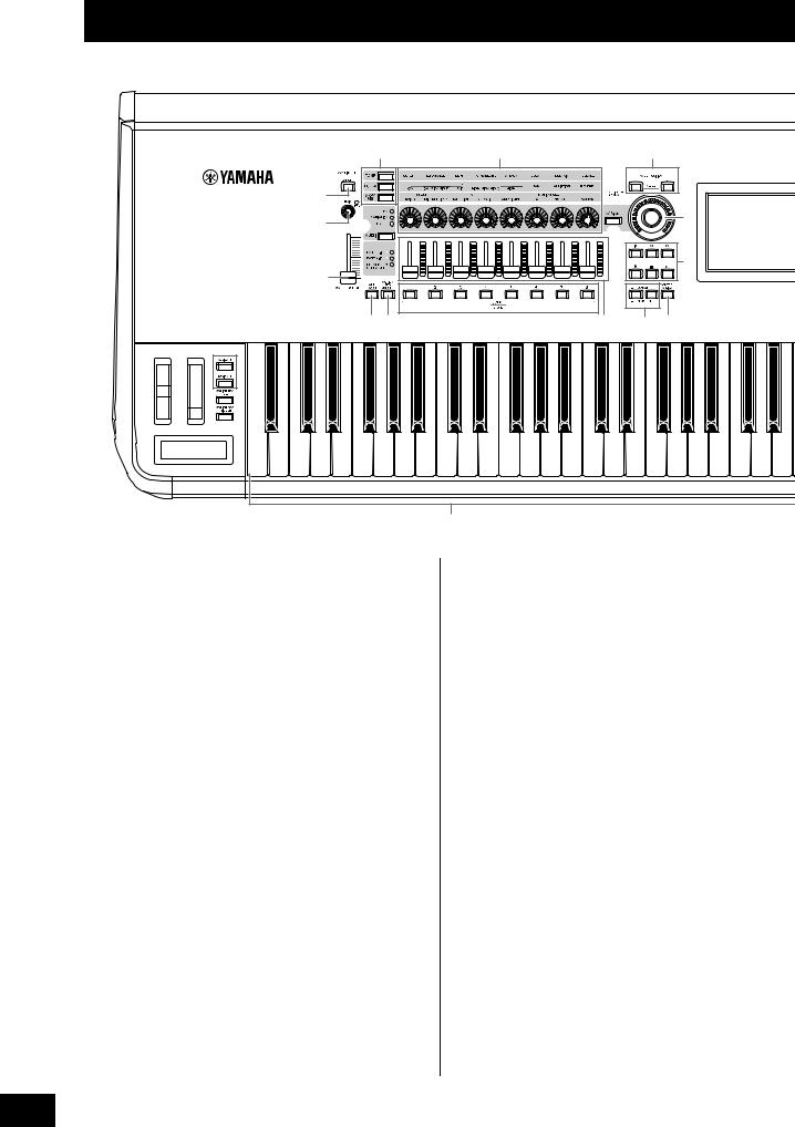
Controls and Functions
Top Panel
|
|
|
! |
|
% |
|
( |
|
|
) |
|
|
|
|
|
|
|
9 |
@ |
|
|
|
A |
|
|
|
|
* |
E |
||
|
|
|
|
|
|||
|
|
|
|
|
|
|
|
|
|
|
|
|
|
|
B |
|
|
8 |
|
|
|
|
|
|
|
|
# $ |
|
& |
^ |
C D |
2 |
3 |
5 |
|
|
|
|
|
|
|
6 |
|
|
|
|
|
|
|
7 |
|
|
|
|
|
|
4 |
|
|
|
|
|
|
|
|
A-1 B-1 C0 D0 E0 |
F0 G0 A0 |
B0 |
C1 |
C2 |
C3 |
|
|
|
|
|
1 |
|
|
1 Keyboard |
|
|
|
|
5 [ASSIGN 1] and [ASSIGN 2] buttons |
||
The MONTAGE6 features a 61-key keyboard, while the |
|
(Assignable switches 1 and 2) |
|||||
MONTAGE7 has 76 keys and the MONTAGE8 has 88 keys. |
|
You can call up the specific Element/Operator of the |
|||||
All are equipped with a touch response feature (both initial |
|
selected Performance by pressing each of these buttons |
|||||
touch and aftertouch). With initial touch, the instrument |
|
during your keyboard performance. In addition, you can |
|||||
senses how strongly or softly you play the keys, and uses |
|
assign other functions to these switches. When one of these |
|||||
that playing strength to alter the sound in various ways, |
|
effects is turned on, the corresponding button will light up |
|||||
depending on the selected Performance. Aftertouch, on the |
|
and vice-versa. |
|
|
|||
other hand, lets you alter the sound by the amount of |
|
|
|
|
|||
pressure you apply to a note after playing it. In addition, any |
6 [MOTION SEQ HOLD] (Motion Sequencer |
||||||
of a variety of functions can be assigned to aftertouch for |
|
hold) button |
|
|
|||
each part. |
|
|
|
|
Pressing this button while the Motion Sequencer is playing, |
||
2 Pitch Bend wheel |
|
|
results in the sound being held or frozen at the exact point in |
||||
|
|
the sequence when the button was pressed. When the hold |
|||||
Controls the pitch bend effect. You can also assign other |
|
effect is turned on, the button lights. |
|||||
functions to this controller. |
|
|
|
|
|
||
3 Modulation wheel |
7 [MOTION SEQ TRIGGER] (Motion Sequencer |
trigger) button |
|
Controls the modulation effect. You can also assign other |
When you press this button, the Motion Sequence starts |
functions to this controller. |
again from the beginning. The button lights fully when |
4 Ribbon Controller |
pressed. |
|
|
This controller is touch sensitive, and is controlled by running |
8 [MASTER VOLUME] slider (page 15) |
your finger lightly across its surface laterally. You can assign |
Move the slider up or down to control the output level from |
various functions to this controller as desired. |
the OUTPUT (BALANCED) [L/MONO]/[R] jacks and the |
|
[PHONES] jack. |
6 MONTAGE Owner’s Manual
Controls and Functions
The illustration shows the MONTAGE8, but the information applies to all models.
F |
L Q |
R |
S |
T d |
a |
e |
|
|
|
|
|
|
|
|
M |
|
|
|
g h |
|
|
|
|
|
|
|
|
H |
N b |
|
|
|
|
|
G |
|
|
|
|
|
|
|
O |
|
|
|
|
|
|
c |
|
|
|
|
|
|
|
|
|
|
i j |
|
J I |
K P |
|
|
f |
|
|
C4 |
C5 |
C6 |
C7 |
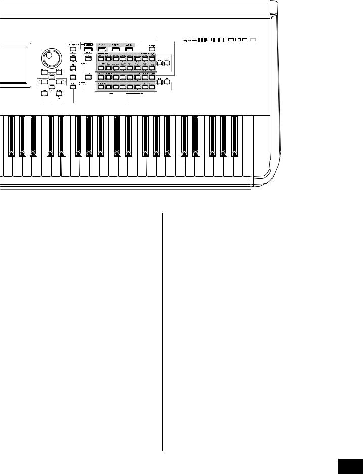
9 A/D INPUT [GAIN] knob (page 44)
Use this to adjust the input gain of the audio signals at the A/D INPUT [L/MONO]/[R] jacks. Turning the knob clockwise increases the gain level.
Detects the peak level and lights up the PEAK LED in red when the level is just short of clipping. Adjust the knob so that the corresponding PEAK LED only occasionally flashes whenever the input signal reaches the maximum level.
NOTE
You may need to change the setting depending on the input level of the external equipment connected to the A/D INPUT [L/MONO]/[R] jacks, in the following order: [UTILITY] [Settings] [Audio I/O] [A/D Input]. When the output level of the connected equipment (such as a microphone, guitar or bass) is low, set this parameter to “Mic.” When the output level of the connected equipment (such as a synthesizer keyboard or CD player) is high, set this parameter to “Line.”
) A/D INPUT [ON/OFF] button (page 44)
Switches whether or not this instrument accepts the audio signal input via the A/D INPUT [L/MONO]/[R] jack. When A/D Input is enabled, the button lights; when disabled, it turns off.
!Knob Function [TONE]/[EQ/FX]/[ARP/MS] button
Use this button to select functions to be assigned to Knobs 1
– 8. The button next to the currently active parameters will light.
You can apply functions to be controlled commonly for all Parts by using the PART [COMMON] button, or to be
controlled for only the selected Part by using the Number A [1] – [16] buttons. The selected button will light.
@ [MULTI] (Multi Part control) button
Use this button to select functions assigned to Knobs 1 – 8. Pressing the button repeatedly switches in the following order: PAN VARIATION REVERB. The lamp next to the currently active parameters will light. All knobs correspond to Parts 1 – 8 or 9 –16 (depending on the currently selected Part).
# [ARP ON/OFF] (Arpeggio on/off) button
Press this button to enable or disable playback of the Arpeggio. If the Arpeggio Switch of the selected Part is set to off, however, pressing this button has no effect. When Arpeggio is enabled, the button lights; when disabled, it turns off.
$[MOTION SEQ ON/OFF] (Motion Sequencer on/off) button
Determines whether the Motion Sequencer is active or not. If the Motion Sequencer switch of the selected Part or Lane is set to off, however, pressing this button has no effect. When the Motion Sequencer is active, the button lights.
MONTAGE Owner’s Manual 7

Controls and Functions
% Knobs 1 – 8
These eight highly versatile knobs let you adjust various important parameters, such as the current Part, Arpeggio tempo, and the Motion Sequencer.
Pressing the knob function [TONE]/[EQ/FX]/[ARP/MS] button, the Multi part control [MULTI] button, or the Assign [ASSIGN] button in the upper left corner changes the functions assigned to the knobs.
^ Control Sliders 1 – 8
These sliders control the volume balance of the sound, by letting you adjust the individual levels of the 16 Parts (1 – 8 / 9 – 16), the eight Elements for Normal Parts (AWM2), the eight FM Operators for a Normal Part (FM-X), and eight Keys of the Drum Part, in different ways depending on the conditions of the various buttons.
|
When PART |
When Number A |
When Number A |
|
[COMMON] |
[1] – [8] buttons |
[9] – [16] |
|
button is on: |
are on: |
buttons are on: |
[PERFORMANCE |
Levels of Parts 1 – 8 |
Levels of Elements/Keys/Operators 1 – 8 of a |
|
CONTROL] |
|
selected Part |
|
|
|
|
|
[PART CONTROL] |
Levels of Parts 1 – 8 |
|
Levels of Parts 9 – |
|
|
|
16 |
|
|
|
|
NOTE
•If all of the Control Sliders are set to the minimum, you may not hear any sound from the instrument, even when playing the keyboard or a Song. If this is the case, raise all the sliders to a suitable level.
•The [MASTER VOLUME] slider controls the overall audio output level of this instrument. On the other hand, the Control Sliders control the level of each Element/Key/Operator of the Parts and the volume for each Part of the Performance as a parameter. Accordingly, the values set via the Control Sliders can be stored as Performance data.
& SCENE [1] – [8] buttons
You can assign different “snapshots” of important Partrelated parameters such as track mute status and the basic Mixing setup to the SCENE [1] – [8] buttons as Part Scenes. When Scene-related parameters are edited and press any of the SCENE [1] – [8] buttons while holding down the [SHIFT] button, the edit is stored for the currently selected [SCENE] button. The stored information is restored by pressing the selected button. The currently selected button fully lights, the button stored information lights dimly, and the button without stored information is turned off.
* [ASSIGN] button
Switches the functions assigned to knobs as Assign 1 – 8. By using the PART [COMMON] button and the Number A [1]
– [16] buttons, you can set whether the functions are commonly effective for all Parts or only for one selected Part. When the effect is turned on, the corresponding button lights.
( KNOB POSITION [1] and [2] buttons
Stores the parameter values of Assign 1 – 8. You can instantly switch between the two buttons.
A Super Knob
Simultaneously controls the parameters (Assign 1 – 8) assigned to the eight knobs.
NOTE
You can also control the Super Knob by using the foot controller (FC7). For details, refer to page 28.
B SEQ TRANSPORT button
These buttons control recording and playback of the Song sequence data.
[T] (Top) button
Instantly returns to the beginning of the current Song (i.e., the first beat of the first measure).
[LL] (Reverse) button
Press briefly to move back one measure at a time.
[RR] (Forward) button
Press briefly to move forward one measure at a time.
[I] (Record) button
Press this to call up the Record setup display. (The button flashes.) Press the [R] (Play) button to start recording. (The [I] (Record) button lights.)
[J] (Stop) button
Press to stop recording or playback. This button can also be used when you want to stop Arpeggio playback, even when Arpeggio is set to continue playback even after the note is released (Arpeggio hold switch is ON).
[R] (Play) button
Press to start playback or recording of a Song. During recording and playback, the button flashes at the current tempo.
C OCTAVE [-] and [+] buttons
Use these buttons to change the octave range of the keyboard. These buttons also function as Transpose [-] and [+] buttons. To lower or raise the pitch of the note in semitone steps, hold down the [SHIFT] button and press the corresponding [-]/[+] button. To restore the normal octave setting, press both buttons simultaneously. The buttons light or flash in different ways depending on the octave setting. For details, see the Reference Manual PDF document.
D [CONTROL ASSIGN] button
While the parameter assignable to controllers is selected on the display, press this button and operate the desired controller for assignment. The controller setting display appears.
E Touch panel LCD
The LCD indicates the parameters and values related to the currently selected operation. You can operate by touching the display.
F Data dial
For editing the currently selected parameter. To increase the value, turn the dial right (clockwise); to decrease the value, turn the dial left (counter-clockwise). If a parameter with a wide value range is selected, you can change the value in broader strokes by quickly turning the dial.
8 MONTAGE Owner’s Manual

G [INC/YES] button
For increasing the value of the currently selected parameter (INC: increment). This button can also be used to execute a Job or Store operation.
Simultaneously hold down the [SHIFT] button and press the [INC/YES] button to quickly increase the parameter value in 10-step jumps.
H [DEC/NO] button
For decreasing the value of the currently selected parameter (DEC: decrement). This button can also be used to cancel a Job or Store operation.
Simultaneously hold down the [SHIFT] button and press the [DEC/NO] button to quickly decrease the parameter value in 10-step jumps.
I Cursor buttons
The cursor buttons move the “cursor” around the display, highlighting and selecting the various parameters.
J [EXIT] button
The menus and displays of the MONTAGE are organized according to a hierarchical structure. Press this button to exit from the current display and return to the previous level in the hierarchy.
K [ENTER] button
Use this button to call up the display of the selected menu, or to execute a Job or Store operation.
Simultaneously hold down the [SHIFT] button and press the [ENTER] button to call up the Tempo setting display.
L [PERFORMANCE] button
Use this button to return to the Performance Play display. The button fully lights when the Performance Play display is shown. This button lights dimly when the Utility display is shown.
Simultaneously hold down the [SHIFT] button and press the [PERFORMANCE] button to call up the Overview display.
M [UTILITY] button
Use this button to call up the Utility display for making overall system settings. The button fully lights when the Utility display is shown and the button lights dimly when other displays are shown.
Simultaneously hold down the [SHIFT] button and press the [UTILITY] button to call up the Quick setup display.
N [EDIT] button
Use this button to call up the display for editing Performances (page 18) and Live Sets (page 30). Also, pressing this button while editing Performance parameters lets you switch between the just-edited sound and its original, unedited condition, allowing you to hear how your edits affect the sound (Compare function). The button lights when the edit display is shown and the button flashes while Compare is active.
O [STORE] button
Use this button to call up the Store display. The button fully lights when the Store display is shown and the button lights dimly when other displays are shown.
Controls and Functions
P [SHIFT] button
Pressing this button along with another button enables you to execute various commands. For details, refer to the “Shift Function List” (page 55).
Q [LIVE SET] button
Use this button to store all your favorite, often-used Performances in a single, easy-to-access location and call them up.
Simultaneously hold down the [SHIFT] button and press the [LIVE SET] button to call up the Live Set display for storing the currently selected Performance to the Live Set. This is one more useful way you can quickly switch among Performances you need in live performance situations. The button fully lights when the Live Set display is shown. If the Live Set display is not shown, the button lights dimly
when the Live Set function is active and the button’s lamp is off when the function is NOT active.
R [CATEGORY SEARCH] button
The Category Search function (page 20) can be accessed by using this button.
Use this button while the Performance Play display is shown to call up the Performance Category Search display for selecting the entire Performance. When the cursor is on the Part name in the Performance Play display, simultaneously hold down the [SHIFT] button and press the [CATEGORY SEARCH] button to call up the Part Category Search display, allowing you to select a sound type for the currently selected Part. The button fully lights when the Category Search display is shown. If the Category Search display is not shown, the button lights dimly when the Category Search function is active and the button’s lamp is off when the function is NOT active.
S [PERFORMANCE CONTROL] button
Use this button with the Number A [1] – [16] buttons, the Number B [1] – [8] buttons, and the Number C [1] – [8] buttons, the PART [MUTE] button, and the PART [SOLO] button to control Performances. When this button is turned on, the following functions can be operated. The button fully lights when it is turned on and the button lights dimly when it is turned off.
Number buttons |
PART [MUTE] button |
PART [SOLO] button |
|
ON |
ON |
Number A [1] – [8] buttons |
Part select (1 – 8) |
Part solo (1 – 8) |
(upper line) |
|
|
|
|
|
Number A [9] – [16] buttons |
Part mute (1 – 8) |
Part solo (1 – 8) |
(lower line) |
|
|
|
|
|
Number B [1] – [8] buttons |
Switch of Motion Sequence types (1 – 8) |
|
|
|
|
Number C [1] – [8] buttons |
Switch of Arpeggio types (1 – 8) |
|
|
|
|
T [PART CONTROL] button
Use this button with the Number A [1] – [16] buttons, the Number B [1] – [8] buttons, and the Number C [1] – [8] buttons, the PART [MUTE] button, and the PART [SOLO] button to control Parts. When this button is turned on, the following functions can be operated. The button fully lights when it is turned on and the button lights dimly when it is turned off.
MONTAGE Owner’s Manual 9

Controls and Functions
Number buttons |
PART [MUTE] |
PART [MUTE] |
|
PART [SOLO] |
|
button and PART |
button ON |
|
button ON |
|
[SOLO] are OFF |
|
|
|
Number A [1] – [8] |
Part select (1 – 8) |
Part mute (1 – 8) |
|
Part select (1 – 8) |
buttons (upper line) |
|
|
|
|
|
|
|
|
|
Number A [9] – [16] |
Part select (9 – 16) |
Part mute (9 – 16) |
|
Part solo (9 – 16) |
buttons (lower line) |
|
|
|
|
|
|
|
|
|
Number B [1] – [8] |
Motion Sequencer for each Part ON/OFF (1 – 8 / 9 – 16) |
|||
buttons |
|
|
|
|
|
|
|
||
Number C [1] – [8] |
Arpeggio for each Part ON/OFF (1 – 8 / 9 – 16) |
|
||
buttons |
|
|
|
|
|
|
|
|
|
a [AUDITION] button
Use this button (in the Performance Play, Live Set, or Category Search displays) to play back or stop a sample phrase showcasing the selected Performance sound. This sample phrase of the Performance is called the “Audition phrase.” The button fully lights when it is ON and the button lights dimly when the Audition function is active such as in the Category Search display.
b PART [COMMON] button
Turning on this button lets you edit the parameters commonly applied to all Parts. The button fully lights when it is turned on and the button lights dimly when it is turned off.
c ELEMENT/OPERATOR [COMMON] button
Turning this button on lets you edit the parameters commonly applied to all Elements/Keys/Operators. The button fully lights when it is turned on and the button lights dimly when it is turned off.
d Number A [1] – [16] buttons
Use these buttons to select Parts on the Performance Play display and the Edit display.
The buttons can also be used to select a main category from the Category Search display. In the Live Set display, the Number A [1] – [4] buttons can be used to select Performances in the first line, and the Number A [9] – [12] buttons can be used to select Performances in the second line. The Number A [5] – [8] buttons can be used to select Live Set pages 1 – 4, and the Number A [13] – [16] buttons can be used to select Live Set pages 5 – 8.
According to each of the displays, the button fully lights when it is selected, the button lights dimly when it is selectable, and the button lamp is off when not selectable. (Only in the case of selecting pages in the Live Set display, this button can be used even if the lamp is off.)
e Number B [1] – [8] buttons
Use these buttons to select Motion Sequencer types on the Performance Play display and to turn the Motion Sequencer for each Part ON/OFF.
The buttons can be used to select Elements/Keys/Operators from the Edit display. The buttons can also be used to select sub categories from the Category Search display. In the Live Set display, the Number B [1] – [4] buttons can be used to select Performances in the third line, and the Number B [5] – [8] buttons can be used to select Live Set pages 9 – 12. According to each of the displays, the button fully lights when it is selected, the button lights dimly when it is selectable, and the button lamp is off when not selectable.
(Only in the case of selecting pages in the Live Set display, this button can be used even if the lamp is off.)
f Number C [1] – [8] buttons
Use these buttons to select Arpeggio types on the Performance Play display and to turn the Arpeggio for each Part ON/OFF.
The buttons can be used to mute Elements/Keys/Operators from the Edit display. The buttons can also be used to select Performances from the Category Search display. In the Live Set display, the Number C [1] – [4] buttons can be used to select Performances in the fourth line, and the Number C [5]
– [8] buttons can be used to select Live Set pages 13 – 16. According to each of the displays, the button fully lights when it is selected, the button lights dimly when it is selectable, and the button lamp is off when not selectable. (Only in the case of selecting pages in the Live Set display, this button can be used even if the lamp is off.)
g PART [MUTE] button
By turning this button on, the Number A [1] – [16] buttons can be used as mute on/off controls. The button fully lights when it is turned on and the button lights dimly when it is turned off. The button can also be used to switch Live Set banks from the Live Set display.
h PART [SOLO] button
By turning this button on, the Number A [1] – [16] buttons can be used as solo on/off controls for Parts. The button fully lights when it is turned on and the button lights dimly when it is turned off. The button can also be used to switch Live Set banks from the Live Set display.
i ELEMENT/OPERATOR [MUTE] button
By turning this button on, the Number B [1] – [8] buttons can be used to select Elements/Keys/Operators 1 – 8, and the Number C [1] – [8] buttons can be used as mute on/off controls for Elements/Keys/Operators 1 – 8. The button lights dimly when it works as mute on, and fully lights when it works as mute off. For operations other than Part editing, the button is off. The button can also be used to switch Live Set banks from the Live Set display.
j ELEMENT/OPERATOR [SOLO] button
By turning this button on, the Number B [1] – [8] buttons (or the Number C [1] – [8] buttons) can be used to as solo on/off controls for Elements 1 – 8. The button fully lights when solo is on, and lights dimly when solo is off. In other situations, except for Part editing operations, the button is off. The button can also be used to switch Live Set banks from the Live Set display.
Number buttons |
ELEMENT/OPERATOR |
ELEMENT/OPERATOR |
|
[MUTE] button ON |
[SOLO] button ON |
Number B [1] – [8] buttons |
Element select (1 – 8) |
Element solo (1 – 8) |
|
|
|
Number C [1] – [8] buttons |
Element mute (1 – 8) |
Element solo (1 – 8) |
|
|
|
10 MONTAGE Owner’s Manual

Rear Panel
Left side of Rear Panel
Controls and Functions
The illustration shows the MONTAGE8, but the information applies to all models.
1 |
2 |
3 |
4 |
USB flash memory device AC outlet 


Computer
Right side of Rear Panel
5 |
6 |
7 |
8 |
9 |
) |
! |
|
|
Headphones |
|
|
Playback equipment |
External MIDI keyboard |
FC7 |
Powered speaker |
|
|
|
FC4, |
FC3, |
|
FC5 |
FC4, |
Microphone |
|
FC5 |
Jack List (Pin Alignment)
Input and Output Jacks |
Polarities |
Balanced/Unbalanced |
Configurations |
|
8 ASSIGNABLE OUTPUT (BALANCED) [L], [R]* |
Tip: Hot (+) |
Balanced |
TRS phone plug |
|
9 OUTPUT (BALANCED) [L/MONO], [R]* |
Ring: Cold (-) |
|
|
Ring |
|
Sleeve: Ground |
|
|
|
) [PHONES] |
Tip: L |
— |
|
|
|
Ring: R |
|
Sleeve |
Tip |
|
Sleeve: Ground |
|
||
|
|
|
|
|
! A/D INPUT [L/MONO], [R] |
Tip: Signal |
Unbalanced |
TS phone plug |
|
|
Sleeve: Ground |
|
|
|
|
|
|
Sleeve |
Tip |
* These jacks are also compatible with TS phone plugs; when used, the connection is unbalanced.
MONTAGE Owner’s Manual 11

Controls and Functions
Left side of Rear Panel
1 [STANDBY/ON] switch
Press to set the power to On or Standby.
2 [AC IN] (AC Power Cord Socket)
Plug the AC power cord supplied with this instrument.
3 [USB TO DEVICE] terminal
Used to connect this instrument to a USB flash memory device. This lets you save data created on this instrument to an external USB flash memory device and load data from a USB flash memory device to the instrument. Save/Load operations can be performed: [UTILITY] [Contents] [Store/Save] or [Load].
NOTE
•Only USB flash memory devices can be recognized by this instrument. No other USB devices (such as a hard disk drive, CDROM drive and USB hub) can be used.
•The instrument supports the USB 1.1 to 3.0 standard. However, note that the transfer speed differs depending on the data type and the condition of this instrument.
4 [USB TO HOST] terminal
Used to connect this instrument to a computer via a USB cable, and allows you to transfer MIDI data and audio data between the devices. Unlike MIDI, USB can handle multiple ports via a single cable (page 50). For information about how the MONTAGE handles Ports, see page 50.
NOTE
Audio data sending capability for the instrument is a maximum 32 channels (16 stereo channels) at a sampling frequency of 44.1 KHz; or maximum 8 channels (4 stereo channels) for a sampling frequency of 44.1 KHz to 192 KHz. Audio data receiving capability is a maximum 6 channels (3 stereo channels).
Right side of Rear Panel
5 MIDI [IN], [OUT], [THRU] terminal
MIDI [IN] is for receiving control or performance data from another MIDI device, such as an external sequencer, letting you control this instrument from the connected separate MIDI device.
MIDI [OUT] is for transmitting all control, performance and playback data from this instrument to another MIDI device, such as an external sequencer.
MIDI [THRU] is simply for redirecting any received MIDI data (via MIDI [IN]) to connected devices, allowing convenient chaining of additional MIDI instruments.
6 FOOT SWITCH [ASSIGNABLE]/[SUSTAIN] jacks
For connection of an optional FC3/FC4/FC5 Footswitch to the [SUSTAIN] jack and a FC4/FC5 Footswitch to the [ASSIGNABLE] jack. When connected to the [SUSTAIN] jack, the Footswitch controls sustain. When connected to [ASSIGNABLE], it can control one of various assignable functions.
NOTE
•The term “FC3” in this Owner’s Manual refers collectively to the FC3 and other footswitches compatible with the FC3, such as the FC3A.
•The term “FC4” in this Owner’s Manual refers collectively to the FC4 and other footswitches compatible with the FC4 such as the FC4A.
7 FOOT CONTROLLER [1]/[2] jacks
For connection of an optional foot controller (FC7, etc.). This jack lets you continuously control one of various different assignable functions for Part edit—such as volume, tone, pitch, or other aspects of the sound (see the Reference Manual PDF document).
8 ASSIGNABLE OUTPUT (BALANCED) [L] and
[R] jacks (TRS balanced output)
Line level audio signals are output from this instrument via these TRS balanced outputs. These outputs are independent of the main output (at the OUTPUT [L/MONO]/ [R] jacks below), and can be freely assigned to any of the Drum Part keys or the Parts. This lets you route specific Parts or sounds for processing with a favorite external effect unit. The Parts which can be assigned to these jacks are as follows:
•Drum Part key to which the drum/percussion instrument is assigned
•Metronome (Click)
•Any Part of a Performance*
* Includes Audio Input Part
For details, see the Reference Manual PDF document.
9 OUTPUT (BALANCED) [L/MONO] and [R] jacks (TRS balanced output)
Line level audio signals are output via these TRS balanced outputs. For monophonic output, use only the [L/MONO] jack.
) [PHONES] (Headphone) jack
This standard stereo phones jack is for connection to a set of stereo headphones. This jack outputs audio signals identical to those from the OUTPUT [L/MONO] and [R] jacks.
! A/D INPUT [L/MONO]/[R] jacks
External audio signals can be input via these phone jacks (1/4" mono phone plug). Various devices such as a microphone, CD player or synthesizer can be connected to these jacks and their audio input signal can be sounded as the Audio Part.
In addition, you can use the special Vocoder feature by connecting a microphone to this [L/MONO] jack and inputting your Voice to the microphone.
You can also use the Envelope Follower and ABS (Audio Beat Sync) features. Envelope Follower is a function for detecting the volume envelope of the input signal waveform and modifying sounds dynamically.
12 MONTAGE Owner’s Manual

Controls and Functions
NOTE
•A guitar or bass having active pickups can be directly connected. However, when using passive pickups, connect the instrument via an effect device.
•The Vocoder/Envelope Follower can be controlled from all Part outputs, and not just the A/D INPUT [L/MONO]/[R] jack.
ABS (Audio Beat Sync) is a function for detecting the beat of the audio signal input from these jacks and synchronizing the beat with the Motion Sequencer or Arpeggio.
Use 1/4" mono phone plugs. For stereo signals (such as from audio equipment), use the [L/MONO]/[R] jacks. For mono signals (such as from a microphone or guitar), use only the [L/MONO] jack.
For details about the Envelope Follower and ABS features, see the Reference Manual PDF document.
MONTAGE Owner’s Manual 13

Setting Up
Power Supply
Connect the supplied AC power cord in the following order. Make sure the [STANDBY/ON] switch on the instrument is set to the Standby position.
1Connect the supplied power cord to the AC IN on the instrument’s rear panel.
2Connect the other end of the power cord to an AC outlet.
Rear panel
AC IN
 Power cord (included)
NOTE
Follow this procedure in reverse order when disconnecting the power cord.
 WARNING
•Use only the AC power cord supplied with your instrument. The use of an inappropriate replacement can lead to overheating or electric shock.
•The power cord supplied with your instrument must not be used with other electrical equipment. Failure to observe this precaution can result in the equipment being damaged or cause a fire.
•Make sure your instrument the voltage requirement for the country or region in which it is being used.
 CAUTION
The instrument remains charged and draws a small amount of power even when the [STANDBY/ON] switch is set to the Standby position. If you intend not to use it for an extended period of time, therefore, make sure to unplug the power cord from the wall outlet.
Connecting Speakers or
Headphones
Since the instrument has no built-in speakers, you will need to monitor the sound of the instrument by using external equipment. Connect a set of headphones, powered speakers, or other playback equipment as illustrated below. When making connections, be sure that your cables have the appropriate ratings.
Powered speaker |
Powered speaker |
(left) |
(right) |
Headphones
OUTPUT L/MONO |
OUTPUT R |
PHONES
Powering Up the System
Make sure the volume settings of the instrument and external devices such as powered speakers are turned to the minimum before turning the power on. When connecting the instrument to powered speakers, turn on the power switch of each device in the following order.
When turning the power on:
First, the instrument (the display will turn on and the buttons will light), then the connected powered speakers.
When turning the power off:
First, the connected powered speakers, then the instrument (the display will turn off and the buttons will turn off).
Keep in mind that the [STANDBY/ON] switch is located at the right side (from the view of the keyboard) of the AC IN socket on the rear panel of the instrument.
[STANDBY/ON] AC IN  switch
14 MONTAGE Owner’s Manual

Auto Power Off function
To prevent unnecessary power consumption, this instrument features an Auto Power Off function that automatically turns the power off if the instrument is not operated for a specified period of time.
Auto Power Off Setting
The amount of time that elapses before the power is automatically turned off can be set.
Instructions: |
[UTILITY] [Settings] [System] [Auto |
|
Power Off] |
|
|
Setting Value (min.): |
off (disables Auto Power Off), 5, 10, 15, 30, |
|
60, 120 |
|
|
Default Setting (min.): |
30 |
|
|
Disabling Auto Power Off (simple method)
Turn the power on while holding down the lowest key on the keyboard. An “Auto power off disabled” message appears briefly and Auto Power Off is disabled. The setting is retained even if the power is turned off.
NOTICE
•Even when the power is turned off, electricity is still flowing to the instrument at the minimum level. To shut off the electricity completely, make sure you unplug the power cord from the wall AC outlet.
•Depending on the instrument status, the power may not turn off automatically, even after the elapse of the specified period of time. Always turn off the power manually when the instrument is not in use.
•When the instrument is not operated for a specified period of time while connected to an external device such as an amplifier, speaker or computer, make sure to follow the instructions in the Owner’s Manual to turn off the power to the instrument and the connected devices in the proper sequence, in order to protect the devices from damage. If you do not want the power to turn off automatically when a device is connected, disable Auto Power Off.
•The setting will revert to its default value if not backed up before the power is turned off.
•When Auto Power Off is set to “off,” the value will be retained even if the backup data saved on another device is loaded to the instrument. When Auto Power Off is set to something other than “off,” the value will be overwritten with loaded data.
NOTE
•The setting time is approximate.
•To turn the power on after Auto Power Off has been executed, press the [STANDBY/ON] switch.
•When the factory settings are restored, the setting time is changed to the default value (30 min.).
Setting Up
Adjusting the Master Volume output
Adjust the overall level of this instrument by using the [MASTER VOLUME] slider.
 Max.
Max.

 Min.
Min.
 CAUTION
Do not listen with the headphones at high volume for long periods of time. Doing so may cause hearing loss.
Restoring the initial factory settings (Initialize All Data)
NOTICE
When the Initialize All Data operation is executed, all the Performance, Song, and any system settings you created on the Utility display will be erased. Make sure you are not overwriting any important data. Be sure to save all important data to your USB flash memory device before executing this procedure (page 53).
1Press the [UTILITY] button or touch the UTILITY icon in the upper right of the screen to call up the Utility display.
2Touch the [Settings] tab in the left of the screen and then touch the [System] tab.
The entire system setting display appears.
3Touch [Initialize All Data] in the lower right of the screen.
The display prompts you for confirmation. To cancel this operation, touch the [Cancel No] in the screen or press the [DEC/NO] button on the panel.
4Touch [Yes] in the screen or press the [INC/ YES] button to execute the Initialize All Data operation.
MONTAGE Owner’s Manual 15
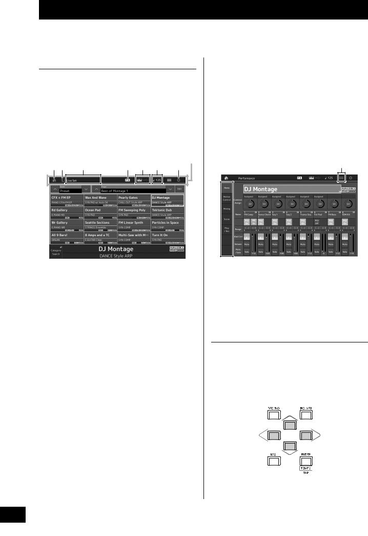
Basic Operation and Displays
The MONTAGE features a convenient touch panel display. You can operate various settings and select desired parameters by directly touching the screen. Furthermore, you can use the data dial and other buttons for display operations.
Display (touch panel) configuration
This section explains the navigation bar and the display selecting tabs which are common to all types of displays. For the purpose of illustration, the Live Set display which appears when the MONTAGE is turned on and the Performance Play display (Home) are used as examples.
NOTE
You can change the start-up display (the display that first appears when the power is turned on). For details about the setting, see page 45.
Live Set display
Navigation bar
12 |
3 |
4 |
5 |
6 |
7 |
1 HOME icon
Moves to the Performance Play display.
2 EXIT icon
Functions same as the [EXIT] button on the panel. Press this icon to exit from the current display and return to the previous level in the hierarchy.
3 INFORMATION area
Displays helpful information, including the currently selected display name.
4 EFFECT icon
Touch the icon to call up the Effect switch display. The icon turns off when any of the Effect blocks (Insertion, System or Master) is off.
5 QUICK SETUP icon
Displays the settings of Local Control ON/OFF and MIDI IN/OUT.
The keyboard-shaped icon lights up when Local Control is set to ON and turns off when Local Control is set to OFF.
When MIDI is set as the MIDI IN/OUT setting, a MIDI connector-shaped icon appears. When USB is set as the MIDI IN/OUT setting, a USB connector-shaped icon appears.
Touch the desired icon to call up the corresponding quick setup display.
6 TEMPO SETTING icon
Displays the tempo of the currently selected Performance. Touch the icon to call up the Tempo setting display.
7 UTILITY icon
Touch the icon to call up the last opened display among the Utility displays.
Performance Play display
8
9
8 LIVE SET icon
Touch the icon to call up the Live Set display.
9 Display selecting tabs
Touch the desired tab to call up the corresponding display.
Moving the cursor
Use these four buttons to navigate the display, moving the cursor around the various selectable items and parameters in the screen. When selected, the relevant item is highlighted (the cursor appears as a dark block with inverse characters). You can change the value of the item (parameter) at which the cursor is located by using the data dial, [INC/YES] and [DEC/NO] buttons.
16 MONTAGE Owner’s Manual
 Loading...