


YAMAHA®
AUTHORIZED PRODUCT MANUAL
YAMAHA
MULTITRACK CASSETTE RECORDER
OPERATING MANUAL

Congratulations on your choice of the New Yamaha MT1X Multitrack Cassette Recorder. The MT1X is a compact multitrack recorder with a recording mixer, and is equipped with numerous versatile functions. Using conventional cassette tapes, the MT1X makes it easy for you to produce
high quality multitrack recordings. Besides use |
as |
a |
multitrack |
recorder, |
the MT1X can also be used as a PA mixer for |
small |
performances, as well |
||
as for editing soundtracks for videos. |
|
|
|
|
To take full advantage of the outstanding array |
of |
features, and |
for years |
|
of trouble-free operation, we urge you to thoroughly read this operating manual. After reading, keep it in a handy place for reference.
CONTENTS |
|
BEFORE OPERATION . . . . . . . . . . . . . . . . . . . . . . . . . ............. |
2 |
PLEASE NOTE THE FOLLOWING PRECAUTIONS .. . . . . . . . . . . |
2 |
THE DIFFERENCE BETWEEN TRACKS AND CHANNELS . . . . . . . . |
3 |
WHAT IS A MULTITRACK CASSETTE RECORDER? . . . . . . . |
3 |
THE CONTROLS AND THEIR FUNCTIONS . . . . . . . . . . . . . . . . . . . . |
4 |
MIXER SECTlON . . . . . . . . . . . . . . . . . . . . . . . . . . . . |
4 |
RECORDER SECTION . . . . . . . . . . . . . . . . . . . . . . . . . . . . . |
7 |
METER AND MONITOR SECTION . . . . . . . . . . . . . . . . . . . . . . . |
9 |
CONNECTOR SECTION .. . . . . . . . . . . . . . . . . . . . . . . . |
11 |
CONNECTION EXAMPLE . . . . . . . . . . . . . . . . . . . . . . . . . . . ..... |
13 |
ABOUT CASSETTE TAPES . . . . . . . . . . . . . . . . . . . . . . . . . . |
14 |
ATTACHING THE STRAP . . . . . . . . . . . . . . . . . . . . . . . . . . . . |
15 |
WHEN USING THE BATTERY PACK . . . . . . . . . . . . . . . . . . . . . |
15 |
MULTITRACK RECORDING TECHNIQUES . . . . . . . . . . . . . . . . . . . . . . . |
16 |
ONE EXAMPLE OF A MULTITRACK RECORDING PROCESS . . . . . . . |
16 |
BEFORE RECORDING . . . . . . . . . . . . . . . . . . . . . . . . . . . . . . . . |
16 |
MULTITRACK RECORDING . . . . . . . . . . . . . . . . . . . . . . . . . . . . . . |
17 |
SYNC-RECORDING . . . . . . . . . . . . . . . . . . . . . . . . . . . . . . . . . . . . . . . |
3 3 |
EDITING VIDEO SOUNDTRACKS . . . . . . . . . . . . . . . . . . . . . . . . |
34 |
MAINTENANCE . . . . . . . . . . . . . . . . . . . . . . . . . . . . . . . . . . . |
34 |
BLOCK DIAGRAM . . . . . . . . . . . . . . . . . . . . . . . . . . . . . . . . . . . . . . . . . . . . . |
35 |
SPECIFICATIONS . . . . . . . . . . . . . . . . . . . . . . . . . . . . . . . . . . . . . . . . . . . . . . . . . . . |
36 |
INTRODUCTION TO THE ACCESSORIES . . . . . . . . . . . . . . . . . . . . . . . . |
37 |
SERVICE . . . . . . . . . . . . . . . . . . . . . . . . . . . . . . . . . . . . . . . . . . |
38 |
1

B E F O R E O P E R A T I O N
 PLEASE NOTE THE FOLLOWING PRECAUTIONS:
• ABOUT CASSETTE TAPE
This unit is designed to be used only with Chromeposition tape, and will not work properly with Ferrichrome tape formulations. CrO tape (Bias: HIGH; EQ: 70µs) should be used. Also, the use of C-120 tapes is not recommended because they exhibit poorer performance, and can be the cause of equipment failure.
• ABOUT dbx
In order to get proper sound reproduction, set the dbx switch ON when playing back tapes recorded with dbx on, and keep it OFF when playing back tapes recorded without dbx.
*dbx and the dbx mark are trademarks of dbx incorporated.
*The dbx system has been manufactured under license of dbx Incorporated.
• USING THE AC ADAPTOR
Please use the AC adaptor supplied with this unit. Other AC adaptors may vary in plug dimensions, polarity, or output voltage, and their use with this unit could cause damage.
• CAUTIONS FOR THE AC ADAPTOR
Do not plug or unplug the AC adaptor with wet hands –- you could receive a very dangerous shock.
To avoid shorts or cord breakage, do not pull the plug out of the AC outlet by pulling on the cord. Be sure to grasp the plug itself and pull it out. When leaving home for an extended period of time, or when the unit will not be used for a long time, unplug the AC adaptor.
NOTE: The AC adaptor has been designed for use with 120V or 220-240V AC, and must not be used in areas with different voltage.
• PRECAUTION AGAINST LIGHTNING
In the event of lightning or electrical storms, unplug the AC adaptor as soon as possible to avoid potential damage.
• DO NOT OPEN THE CABINET
To avoid electrical shock or damage to the unit, do not open the cabinet and tamper with the parts or circuits inside.
• CONNECTING OTHER EQUIPMENT
Make sure the power switch is OFF and the input fader is all the way down when connecting other equipment.
• M0VING THE UNIT
To prevent shorts or breakage, make sure all connection cords have been removed from the unit before moving it.
• CLEANING THE CABINET
Do not clean the unit with benzene or other powerful solvents, and avoid the use of aerosol insecticides near the unit. Clean the unit only with a soft, dry cloth.
FCC CERTIFICATION (USA)
This equipment generates and uses radio frequency energy and if not installed and used properly, that is, in strict accordance with the manufacturer’s instructions, may cause interference to radio and television reception. It has been type tested and found to comply with the limits for a Class B computing device in accordance with the specifications in Subpart J of Part 15 of FCC Rules, which are designed to provide reasonable protection against such interference in a residential installation. However, there is no guarantee that interference will not occur in a particular installation. If this equipment does cause interference to radio or television reception, which can be determined by turning the equipment off and on, the user is encouraged to try to correct the interference by one or more of the following measures:
Reorient the receiving antenna.
Relocate the computer with respect to the receiver. Move the computer away from the receiver. Plug the computer into a different outlet so that
computer and receiver are on different branch circuits.
If necessary, the user should consult the dealer or an experienced radio/television technician for additional suggestions. The user may find the following booklet prepared by the Federal Communications Commission helpful:
“How to identify. and Resolve Radio-TV interference problems”.
This booklet is available from the U.S. Government Printing Office, Washington, DC 20402, Stock No. 004-000-00345-4.
2
THE DIFFERENCE BETWEEN TRACKS AND CHANNELS
The words “track” and “channel” are often confused. In order to properly operate this unit, it is necessary to understand the meanings of these terms.
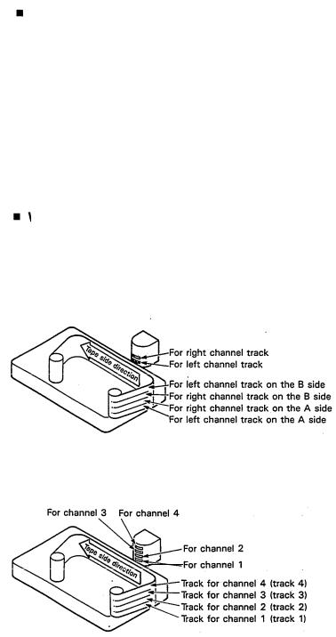
TRACK:
The “band” on the tape itself where a certain signal is recorded. The tape inside a cassette has four different tracks, enabling the recording of four distinct signals. For conventional recordings, there are two tracks (stereo left and right) on each side of the tape.
WHAT IS A MULTITRACK CASSETTE RECORDER?
CHANNEL:
The route of a signal input or output. In the input side, this unit has four INPUT channels and two AUX channels. The output side consists of one stereo channel (made up of two mono channels) and an AUX channel.
The difference between the MT1X multitrack cassette recorder and a conventional stereo cassette deck is shown below.
CONVENTIONAL STEREO CASSETTE DECK
MT1X MULTITRACK CASSETTE RECORDER
The diagram shows how a conventional stereo cassette deck records and plays back music. The four tracks on a cassette tape represent the left and right (for stereo) sound for each side of the tape. The MT1X uses these four tracks for single-direction recording and playback on only one side of a cassette tape.
Conventional stereo cassette recorders always record and play back in the same mode, with the tape side (direction) determining which two tracks will be used.
These recorders do not allow separate selection of tracks for recording and playback.
Multitrack recorders, however, allow you to record or playback tracks separately as you choose. This enables a greater degree of recording and playback freedom not possible with conventional cassette recorders.
3

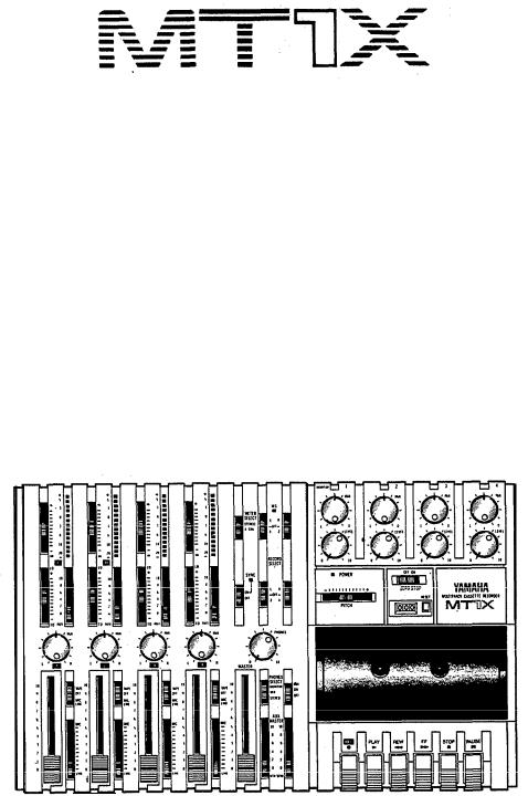
THE CONTROLS AND THEIR FUNCTIONS
This section explains the names and functions of all the knobs, sliders, and switches for the mixer, recorder, meter/ monitor, and connector sections. Familiarize yourself with them in order to take full advantage of the MT1X’s versatile functions.
MIXER SECTION
INPUT |
SELECTOR |
SWITCHES |
TAPE: |
Set the switch to this position to playback |
These three-position |
switches are provided for each |
|
material which has already been recorded on |
|
channel. Position them according to the operation to be |
|
this channel. Channels 1—4 correspond to |
||
performed. |
|
|
|
tracks 1—4 on the tape. |
MIC/LINE: Set this switch to the proper position when |
|
|
||
|
the output of a microphone, keyboard instru- |
|
|
|
|
ment, or electric guitar is connected to the |
|
|
|
|
input jack |
on the front panel. |
|
|
OFF: |
Be sure to |
set the switch to this position |
|
|
|
when the channel is not being used, or when |
|
|
|
|
you don’t want to playback material already |
|
|
|
|
recorded on the track. Although sliding the |
|
|
|
|
input fader |
to the “O” position will stop |
|
|
the signal, it’s a good idea to also set the switch to OFF.
4
GAIN CONTROLS
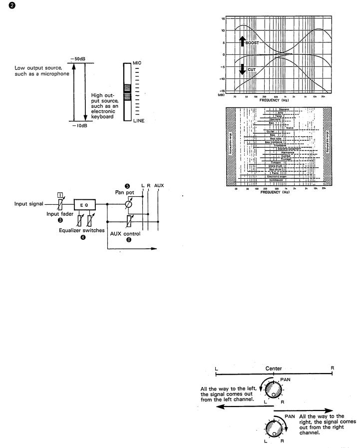
The controls adjust the input level of the channel to match the output level of a microphone or instrument connected to input jack  Control from -10dB to -50db is possible. Adjust the output level of the
microphone or instrument as outlined in its instruction b o o k l e t .
 INPUT FADERS
These controls adjust the volume of the signal input, and send it to the  equalizer. Each control is used for setting the sound level of its channel when mixing it with the signals of other channels. Position “7” on the scale is considered ideal for the lowest noise and distortion characteristics.
Be sure to set the control to “O” for channels not being used.
 EQUALIZER CONTROLS
These controls are used to adjust the tonal characteristics of the input signal, or the channel output during playback of previously recorded material. The LO (low) controls adjust the frequencies centering around 100Hz, while the HI (high) controls adjust the frequencies centering around 10KHz, with a 10dB boost or cut range for both controls. Use of these equalizer controls will help you to get the type of sound you desire, and allow you
to bring the sound “forward”, “clean up” unclear sounds, and “push down” sounds at annoying frequencies.
In order to properly use these equalizers, it’s important to understand the frequency response characteristics of various musical instruments. This is particularly true when trying to “change” the sound of a certain instrument, because you should know that instrument’s harmonic sound components as well. For example, the normal frequency range of a bass drum is between 50Hz and 150Hz. To bring out this sound so you can feel it better, the LO (low) control (which centers on the 100Hz frequency band) can be moved up a little. But the harmonic sound components are around 10KHz, so the HI (high) control should also be moved up a little to achieve
5 the proper sound profile of the bass drum.
SOUND CHARACTERISTICS OF THE EQUALIZER AND VARIOUS MUSICAL INSTRUMENTS
-----Normal frequency ----- Harmonic sound components
If accurate and comprehensive sound equalization is required, connect a graphic equalizer or a parameteric equalizer between the sound source and the input jack.
When recording material that you will intend to “pingpong” (see “Ping-ponging” on page 25), later, give the input somewhat of a high boost with the Hi control to help preserve the high frequency response when the track is re-recorded.
 PAN (PAN POT) CONTROLS
After volume level and equalizing, the input signal is sent to these controls. During mixdown (see “Mixdown” on page 31), each control helps determine the acoustsic “position” of the signal in regards to the stereo field. Turning the control all the way to the left puts the signal all the way over to the left side of the stereo soundspace; turning the control to the right sends the signal towards the right. At dead center, the signal comes out equally from the left and right channels.
These controls are also useful in ping-ponging (see “Pingponging” on page 25).
AUX CONTROLS |
|
|
The MT1X is equipped with an AUX SEND jack |
and two (left and right) AUX RETURN jacks |
When special |
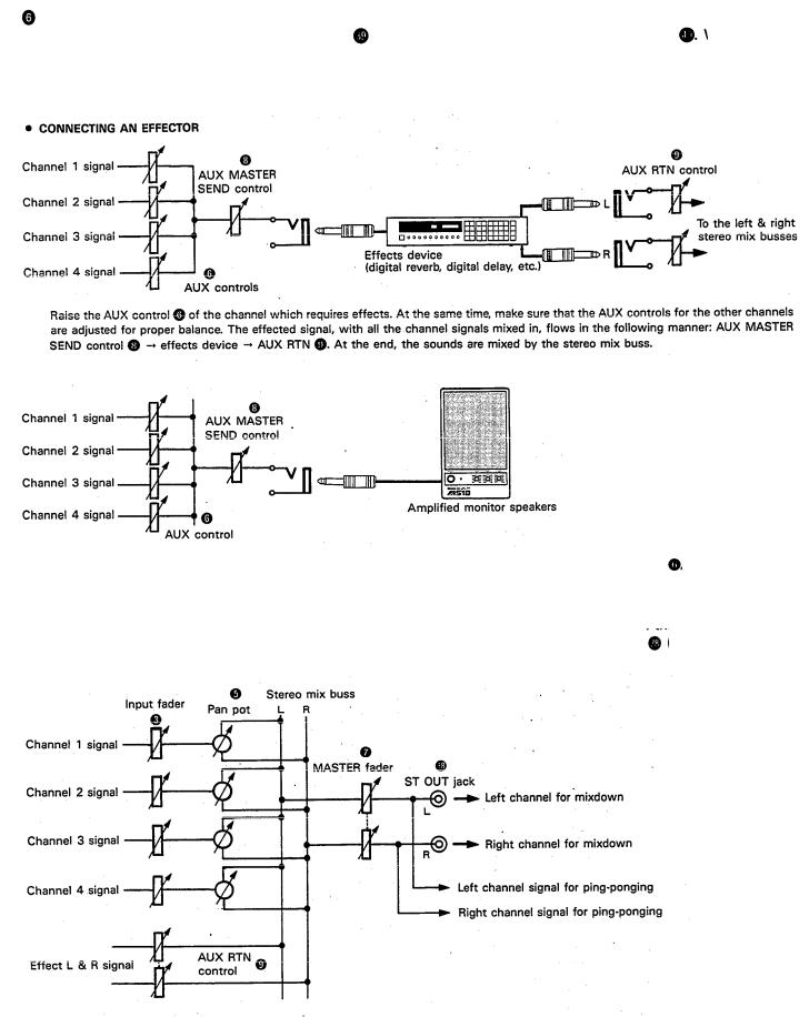
acoustic effects are desired on a certain channel, reverbs or delay effects can be connected between these jacks to provide only the desired effect to the desired channel. Amplified monitor speakers can also be connected to the AUX SEND jack. Each AUX control adjusts the sources connected to the AUX SEND jack in the following manner.
•CONNECTING MONITOR SPEAKERS
Performers or sound mixers can control the level balance of the four channels (instruments) with the AUX controls , with the total output level adjusted by the AUX MASTER SEND control 
 MASTER FADER
This controls the level of all the input faders, as well as the final level of the effected signal of the AUX RTN control  and the sound mixed through the stereo mix buss. The output level of the ST OUT jack (the recording level
at mixdown) and the recording level during ping-ponging are also adjusted with this control.
Set the control input faders at “7” for best results. |
6 |
 AUX MASTER SEND CONTROL
This control adjusts the level of the effect-mixed signals from each channel (adjusted by each AUX control
as well as the AUX signal for monitoring use. The final output is through the AUX SEND jack 
 AUX RETURN CONTROL
This control adjusts the input level of effects or submixers connected to the AUX RTN jack . The level of effect in relation to the sound can be set with this control.
 SYNC SWITCH
Normally left in the “OFF” position, this switch should be turned “ON” if this unit is to be used for synchronized operation with MIDI products like synthesizers and rhythm machines. Synchro operation is explained in the
section on Sync jack |
or in the Sync-Recording sec- |
tion on page 33. |
|
 Power Indicator
This indicator lights when the power switch on the rear panel is turned on.
7

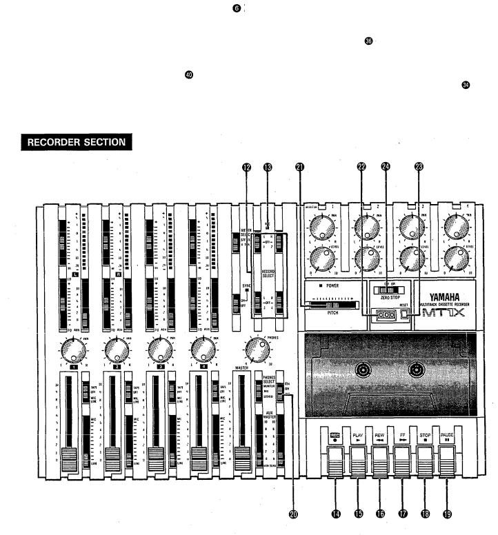
RECORD SELECT SWITCHES
These switches are used to choose the signal to be recorded. The upper left switch is for track 1, the upper right switch is for track 2, the lower left switch is for track 3, and the lower right switch is for track 4.
When the track is not to be recording, set the corresponding switch to the OFF position. Switch ON only those switches corresponding to the tracks which are to record. The panel indications for “L” and “R” correspond to the stereo left and right signals, whereas “1”, “2”,“3”and “4” correspond to the signal from the 1, 2, 3, and 4 input channels. Those signals are recorded on their respective track when the switches are in position.
NOTE: Tracks 1 and 3 cannot be recorded on the right stereo signal, and tracks 2 and 4 cannot be recorded on the left stereo signal.
 REC INDICATOR
Recording status is indicated in the following three ways:
No indication:
All tracks 1—4 are not recording.
Flashing:
All tracks 1—4 are in recording standby mode. By
pushing only the REC switch |
the tape is put into |
the recording standby mode. |
|
Indication ON: |
|
All tracks 1—4 are recording, or in the REC pause mode. To resume recording during REC pause, press the PAUSE switch
REC SWITCH
When this switch is pressed, the PLAY switch also moves, and the unit goes into the recording mode. However, if the RECORD SELECT switches for all tracks
1—4 are switched OFF, nothing will be recorded. NOTE: When the REC switch is pressed down, noise
occurs which is recorded on the tape. In order to prevent this, we recommended the use of the
PAUSE switch  Press the PAUSE switch first, then press the REC switch. To start recording, press the PAUSE switch again to shift out of the REC pause mode and into the recording mode.
 PLAY SWITCH
Press this switch for playback. However, if the input selector switch (1) of a track is not in the TAPE position, the sound will not be heard on the stereo buss.
 REW SWlTCH (REWIND)
Use this switch to rewind the tape. Pressing it when the MT1X is in the PLAY mode enables you to hear the sound of the tape while it rewinds. This feature is useful for finding the beginning of a song or other recorded material.
 FF SWITCH (FAST FORWARD)
Use this switch to quickly advance the tape forward. Pressing it when the MT1X is in the PLAY mode enables you to hear the sound of the tape while it is moved forward. This feature is useful for cueing up the start of a subsequent song or other recorded material on the tape.
 STOP SWITCH
Press this to stop tape run.
 PAUSE SWITCH
Press this switch to momentarily stop playback or recording in progress. Press it again to restart.
dbx SWITCH
Ordinary cassette tapes don’t have sufficient dynamic range (the level difference between the softest sounds and the loudest peaks) to adequately record highly dynamic music. If the dbx switch is put “ON” during recording, highly dynamic music signals can be adequately handled, while the hiss noise inherent to cassette tapes is kept down below the range of human hearing.
If the dbx switch is kept “ON” during recording, it must also be kept “ON” during playback.
 PITCH CONTROL
During recording or playback, this control can be used to vary the tape running speed from +10% to -10%. The pitch of voices or musical instruments also varies in proportion to tape speed.
Under normal conditions, the control should be in the center position. When overdubbing (playing back a recorded passage while recording new material on a different track) the pitch of the previously recorded material can be altered to match the new material if necessary. This feature can also be used to obtain certain special effects during recording.
 TAPE COUNTER
This displays the amount of tape run.
 RESET SWITCH
Press this switch to reset the tape counter to “000”. Pressing this switch at the start of recording, or at the beginning of a song, makes it easy to cue up the selection from the start.
ZERO STOP SWITCH
If this switch is set “ON” during rewinding, the tape will stop when the tape counter reaches “999”. During multitrack recording, this feature is convenient for repeated playback or recording operations after rewind.
8
METER AND MONITOR SECTION
METER SELECT SWITCH
This switch is used to select the signal for level indication by the Peak Level Meters
STEREO Position:
The level of the signal output through the ST OUT jacks is indicated. The meter on the far left shows the level of the Left channel of the stereo signal, while the second meter from the left shows the level of the Right channel. Setting to this position during pingponging or mixdown operations enables easy reading of the recording level.
4 TRK Position:
Set the switch in this position to display the level of each track. Starting from the far left, each meter corresponds to tracks 1—4. During playback, the playback level is displayed; during recording, the recording level is displayed. Setting the switch to this position during overdubbing enables easy reading of the recording level.
PEAK LEVEL METERS
There are 14 LED indicators in each meter which show a range from - 20dB to + 5dB. During recording, setting levels high (but below the point where the recording becomes distorted) will ensure the greatest dynamic range with the lowest possible noise. An ideal point is when the LED indicators for 0dB and above flash occasionally.
During stereo signal level indication, the actual specified output from the ST OUT jacks is
(at a 50K ohm load) when the LED indicators start to flash at 0dB.
9
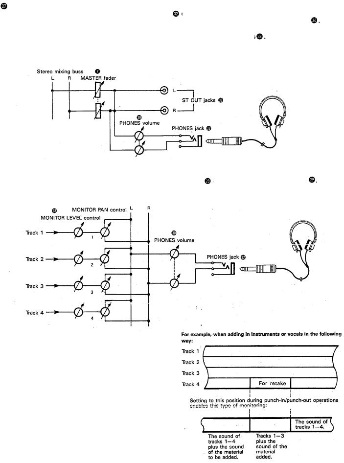
PHONES SELECT SWITCH |
on the front panel to monitor the sound. This switch |
|
You can plug a set of headphones into the PHONES jack |
||
is used to select the signal to be monitored. Control the volume level with the PHONES volume control |
||
STEREO Position: |
|
The Left and Right chan- |
Put the switch in this position to monitor the signal output through the ST OUT jacks |
||
nels of the stereo signal will be heard through the headphones.
When setting to this position during ping-ponging or mixdown operations, the mixed signal of all the instruments can be monitored.
MONITOR Position:
This position is for monitoring the signal of each track. You can freely monitor while mixing the sound of each track
during recording or playback. Using the MONITOR LEVEL Controls |
and the MONITOR PAN Controls |
, set the |
desired level and position for each track. |
|
|
Track
MIX Position:
This position allows you to simultaneously monitor both the sound heard in the STEREO position and the sound heard in the MONITOR position. Setting to this position during punch-in/punch-out operations will enable the type of monitoring shown below. (Refer to “Punch-in/Punch-out” on page 27).
10
MONITOR LEVEL CONTROLS
When setting the PHONES SELECT Switch to the MONITOR position, these level controls are used for each track to achieve a level balance for easy monitoring. Use these controls freely and independently to maintain a desired level balance during overdubbing operations, when the addition of a new signal changes the volume.
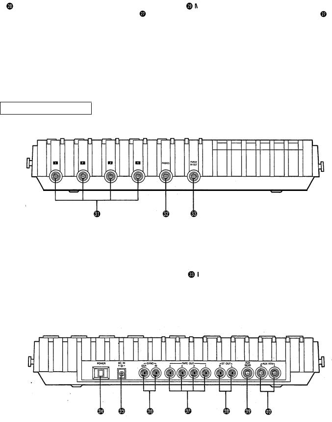
CONNECTOR SECTION
FRONT PANEL
MONITOR PAN CONTROLS
When setting the PHONES SELECT Switch to the MONITOR position, use these pan controls for each track to achieve the desired stereo positioning for each track. Use these controls freely and independently to maintain the desired stereo position balance during overdubbing operations, when the addition of a new signal changes the stereo image.
 PHONES CONTROL
This control adjusts the volume of the headphones (See page 9).
 INPUT JACKS
These four jacks are for the connection of microphones or electric and electronic instruments. With a high input impedance of 10K ohms, and a specified input level range of -10dB to -50dB, a wide variety of instruments and microphones can be used.
When directly connecting an electric guitar, the use of an special electric guitar preamp to increase the input level will assure recordings of better sound quality.
 PHONES JACK
Plug a set of headphones into this jack for monitoring. Please use headphones rated from 8-—0 ohms for best results.
PUNCH IN/OUT JACK
By connecting the optional FS-1 footswitch to this jack, you can control punch-in/punch-out operations. by foot.
REAR PANEL
11
 Loading...