


MG16XU
Table of contents
 Loading...
MIXING CONSOLE
Owner’s Manual
MG16/4
MG12/4
Making the Most Of Your Mixer
Pages 6 to 17
E
MG16/4, MG12/4
2
Precautions
—For safe operation—
WARNING
●
Connect this unit’s AC power adaptor only to an AC outlet of the
type stated in this Owner’s Manual or as marked on the unit.
Failure to do so is a fire and electrical shock hazard.
●
Do not allow water to enter this unit or allow the unit to become
wet. Fire or electrical shock may result.
●
Do not place a container with liquid or small metal objects on
top of this unit. Liquid or metal objects inside this unit are a fire
and electrical shock hazard.
●
Do not place heavy objects, including this unit, on top of the
power cord. A damaged power cord is a fire and electrical shock
hazard. In particular, be careful not to place heavy objects on a
power cord covered by a carpet.
●
Do not scratch, bend, twist, pull, or heat the power cord. A dam-
aged power cord is a fire and electrical shock hazard.
●
Do not remove the unit’s cover. You could receive an electrical
shock. If you think internal inspection, maintenance, or repair is
necessary, contact your dealer.
●
Do not modify the unit. Doing so is a fire and electrical shock
hazard.
●
If lightning begins to occur, turn off the power switch of the unit
as soon as possible, and unplug the power plug from the electri-
cal outlet.
●
If there is a possibility of lightning, do not touch the power plug
if it is still connected. Doing so may be an electrical shock haz-
ard.
●
Use only the included AC power adaptor (PA-20) for this unit.
Using other types may be a fire and electrical shock hazard.
●
If the power cord is damaged (i.e., cut or a bare wire is exposed),
ask your dealer for a replacement. Using the unit with a damaged
power cord is a fire and electrical shock hazard.
●
Should this unit and AC adaptor be dropped or the cabinet be
damaged, turn the power switch off, remove the power plug from
the AC outlet, and contact your dealer. If you continue using the
unit without heeding this instruction, fire or electrical shock may
result.
●
If you notice any abnormality, such as smoke, odor, or noise, or
if a foreign object or liquid gets inside the unit, turn it off imme-
diately. Remove the power plug from the AC outlet. Consult your
dealer for repair. Using the unit in this condition is a fire and
electrical shock hazard.
CAUTION
●
Keep this unit away from the following locations:
- Locations exposed to oil splashes or steam, such as near cook-
ing stoves, humidifiers, etc.
- Unstable surfaces, such as a wobbly table or slope.
- Locations exposed to excessive heat, such as inside a car with
all the windows closed, or places that receive direct sunlight.
- Locations subject to excessive humidity or dust accumulation.
●
Hold the power plug when disconnecting it from an AC outlet.
Never pull the cord. A damaged power cord is a potential fire and
electrical shock hazard.
●
Do not touch the power plug with wet hands. Doing so is a
potential electrical shock hazard.
●
To relocate the unit, turn the power switch off, remove the power
plug from the AC outlet, and remove all connecting cables. Dam-
aged cables may cause fire or electrical shock.
●
Do not cover or wrap the AC power adaptor with a cloth or blan-
ket. Heat may build up under the cloth or blanket, melting the
case, or causing fire. Use only in a well-ventilated environment.
●
If you know you will not use this unit for a log period of time,
such as when going on vacation, remove the power plug from the
AC outlet. Leaving it connected is a potential fire hazard.
Installation
Operation
In case an abnormality occurs during operation
Installation
Operation

Precautions
MG16/4, MG12/4
3
—For correct operation —
●
XLR-type connectors are wired as follows: pin 1: ground, pin 2:
hot (+), and pin 3: cold (–).
●
Insert TRS phone jacks are wired as follows: sleeve: ground, tip:
send, and ring: return.
●
The performance of components with moving contacts, such
switches, rotary controls, faders, and connectors, deteriorates
over time. The rate of deterioration depends on the operating
environment and is unavoidable. Consult your dealer about
replacing defective components.
●
Using a cell phone (mobile telephone) near this unit may induce
noise. If noise occurs, use the telephone away from the unit.
Copying of the commercially available music data and/or digital audio files is strictly prohibited except for your personal use.
Illustration examples shown herein are for explanatory purposes only, and may not match actual appearance during operation.
The company names and product names in this Owner’s Manual are the trademarks or registered trademarks of their respective companies.
• This applies only to products distributed by Yamaha-Kemble Music (U.K.) Ltd. (2 wires)
Connector pin assignments
Replacing abrasive parts
Influence on cell phone usage
●
Always turn the power off when the mixer is not in use.
●
Even when the power switch is in the “STANDBY” position, electricity is still flowing to the mixer at the minimum level. When you are
not using the mixer for a long time, make sure you unplug the AC power adaptor from the wall AC outlet.
IMPORTANT NOTICE FOR THE UNITED KINGDOM
Connecting the Plug and Cord
IMPORTANT. The wires in this mains lead are coloured in accordance with the following code:
BLUE : NEUTRAL
BROWN : LIVE
As the colours of the wires in the mains lead of this apparatus may not correspond with the coloured makings identifying the terminals in your
plug proceed as follows:
The wire which is coloured BLUE must be connected to the terminal which is marked with the letter N or coloured BLACK.
The wire which is coloured BROWN must be connected to the terminal which is marked with the letter L or coloured RED.
Making sure that neither core is connected to the earth terminal of the three pin plug.

MG16/4, MG12/4
4
Introduction
Thank you for your purchase of the YAMAHA MG16/4 or MG12/4 mixing console. This mixing
console combines ease of operation with support for multiple usage environments, and is
ideal for SR setups, installed systems, and many other such applications.
Please read through this Owner’s Manual carefully before beginning use, so that you will be
able to take full advantage of the mixer’s superlative features and enjoy trouble-free operation
for years to come.
●
The MG16/4 provides 16 input channels that can assign to Ste-
reo or Group output.
●
The MG12/4 provides 12 input channels that can assign to Ste-
reo or Group output.
●
The monitor includes a convenient C-R OUT jack. This jack can
be used to monitor the main Stereo output, the PFL signal, or the
Group 1-2 signals.
●
The mixer includes dual AUX SEND jacks and a single
RETURN jack. The two independent AUX buses may be used as
sends to external effectors and monitor systems.
●
Phantom power supply enables easy connection to condenser
microphones that run on external power.
●
The mixer provides channel-specific INSERT I/O jacks for input
channels 1 to 8 (MG16/4) or 1 to 4 (MG12/4). These jacks make
it possible to insert different effectors into different channels.
●
Input channels 1 to 8, 9/10, and 11/12 (MG16/4), and 1 to 4, 5/6,
and 7/8 (MG12/4) are each equipped with both an XLR mic
input jack and a TRS phone-type line jack. Input channels 13/14
and 15/16 (MG16/4), and 9/10 and 11/12 (MG12/4) are each
equipped with both a TRS line input jack and an RCA line input
jack. This wide assortment of connectors enables connection to
many different devices, from microphones to line-level devices
to stereo-output synthesizers.
Introduction ............................................................... 4
Features ............................................................... 4
Contents .............................................................. 4
Before Turning on the Mixer ................................. 5
Turning the Power On .......................................... 5
Making the Most Of Your Mixer ................................. 6
1
A Place For Everything and Everything
In Its Place ....................................................... 7
2
Where Your Signal Goes Once It’s Inside
the Box .......................................................... 10
3
The First Steps in Achieving Great Sound .... 11
4
External Effects, Monitor Mixes,
and Groups .................................................... 13
5
Making Better Mixes....................................... 16
Front & Rear Panels ................................................ 18
Channel Control Section .................................... 18
Master Control Section ...................................... 20
Rear Input/Output Section ................................. 22
Setting Up ............................................................... 24
Setup Procedure ................................................ 24
Setup Examples ................................................ 24
Rack Mounting ................................................... 26
Appendix ................................................................. 27
Specifications .................................................... 27
Dimensional Diagrams ....................................... 29
Block Diagram and Level Diagram .................... 30
Features
Contents
Introduction
MG16/4, MG12/4
5
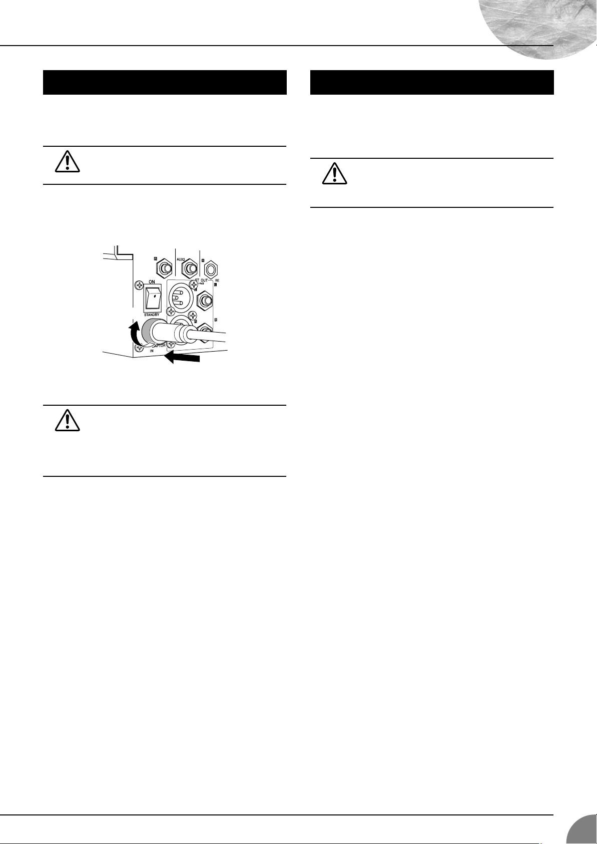
(1) Be sure that the mixer’s power switch is in the STANDBY
position.
Use only the PA-20 adaptor included with this mixer.
Use of a different adaptor may result in equipment
damage, overheating, or fire.
(2) Connect the power adaptor to the AC ADAPTOR IN con-
nector (
1
) on the rear of the mixer, and then turn the fas-
tening ring clockwise (
2
) to secure the connection.
(3) Plug the power adaptor into a standard household power outlet.
• Be sure to unplug the adaptor from the outlet when
not using the mixer, or when there are lightning
storms in the area.
• To avoid generating unwanted noise, make sure
there is adequate distance between the power
adaptor and the mixer.
Press the mixer’s power switch to the ON position. When you are
ready to turn the power off, press the power switch to the
STANDBY position.
Note that trace current continues to flow while the
switch is in the STANDBY position. If you do not plan
to use the mixer again for a long while, please be sure
to unplug the adaptor from the wall outlet.
Before Turning on the Mixer
1
2
Turning the Power On
MG16/4, MG12/4
6
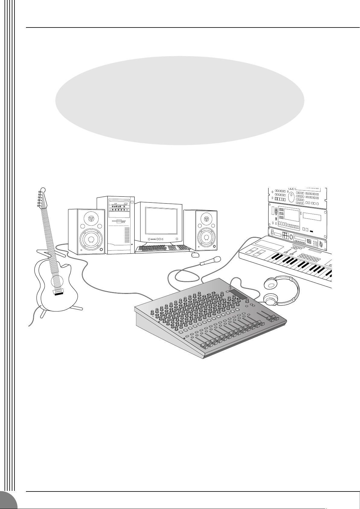
Making the Most Of Your Mixer
An Introduction
You’ve got yourself a mixer and now you’re ready to use it.
Just plug everything in, twiddle the controls, and away you go … right?
Well, if you’ve done this before you won’t have any problems, but if this is
the first time you’ve ever used a mixer you might want to read through this
little tutorial and pick up a few basics that will help you get better
performance and make better mixes.
Making the Most Of Your Mixer
MG16/4, MG12/4
7
A Place For Everything and Everything In Its Place
1-1. A Plethora Of Connectors—What Goes Where?
Questions you’re likely to encounter when setting up a system for the first time might include “Why all
these different types of connectors on the back of my mixer?” and “What’s the difference?”.
Let’s start by taking a look at the most common connector types.
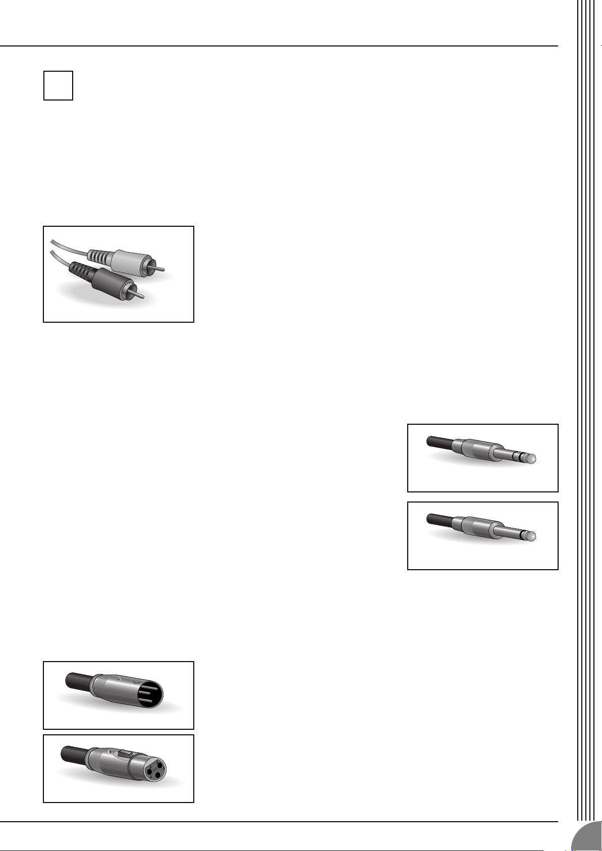
The Venerable RCA Pin Jack
This is the “consumer connector,” and the one that has been most commonly used
on home audio gear for many years. Also known as “phono” jacks (short for
”phonogram”), but the term isn’t used much these days—besides, it’s too easily
confusable with “phone” jacks, below. RCA pin jacks are always unbalanced, and
generally carry a line-level signal at –10 dB, nominal. You’re most likely to use this
type of connector when connecting a CD player or other home audio type source
to your mixer, or when connecting the output of your mixer to a cassette recorder
or similar gear.
The Versatile Phone Jack
The name “phone jack” arose simply because this configuration was first
used in telephone switchboards. Phone jacks can be tricky because you
can’t always tell what type of signal they’re designed to handle just by
looking at them. It could be unbalanced mono, unbalanced stereo,
balanced mono, or an insert patch point. The connector’s label will
usually tell you what type of signal it handles, as will the owner’s manual
(you
do
keep your manuals in a safe place, don’t you?). A phone jack that
is set up to handle balanced signals is also often referred to as a “TRS”
phone jack. “TRS” stands for Tip-Ring-Sleeve, which describes the
configuration of the phone plug used.
The Sturdy XLR
This type of connector is generally referred to as “XLR-type,” and almost always
carries a balanced signal. If the corresponding circuitry is designed properly,
however, XLR-type connectors will also handle unbalanced signals with no
problem. Microphone cables usually have this type of connector, as do the inputs
and outputs of most professional audio gear.
1
White
Red
Stereo/TRS phone plug
Mono phone plug
Male
Female
Making the Most Of Your Mixer
MG16/4, MG12/4
8
1-2. Balanced, Unbalanced—What’s the Difference?
In a word: “noise.” The whole point of balanced lines is noise rejection, and it’s something they’re very
good at. Any length of wire will act as an antenna to pick up the random electromagnetic radiation we’re
constantly surrounded by: radio and TV signals as well as spurious electromagnetic noise generated by
power lines, motors, electric appliances, computer monitors, and a variety of other sources. The longer
the wire, the more noise it is likely to pick up. That’s why balanced lines are the best choice for long
cable runs. If your “studio” is basically confined to your desktop and all connections are no more than a
meter or two in length, then unbalanced lines are fine—unless you’re surrounded by extremely high lev-
els of electromagnetic noise. Another place balanced lines are almost always used is in microphone
cables. The reason for this is that the output signal from most microphones is very small, so even a tiny
amount of noise will be relatively large, and will be amplified to an alarming degree in the mixer’s high-
gain head amplifier.
To summarize:
Microphones: Use balanced lines.
Short line-level runs: Unbalanced lines are fine if you’re in a relatively noise-free environment.
Long line-level runs: The ambient electromagnetic noise level will be the ultimate deciding factor, but
balanced is best.
■
How Do Balanced Lines Reject Noise?
** Skip this section if technical details make you queasy. **
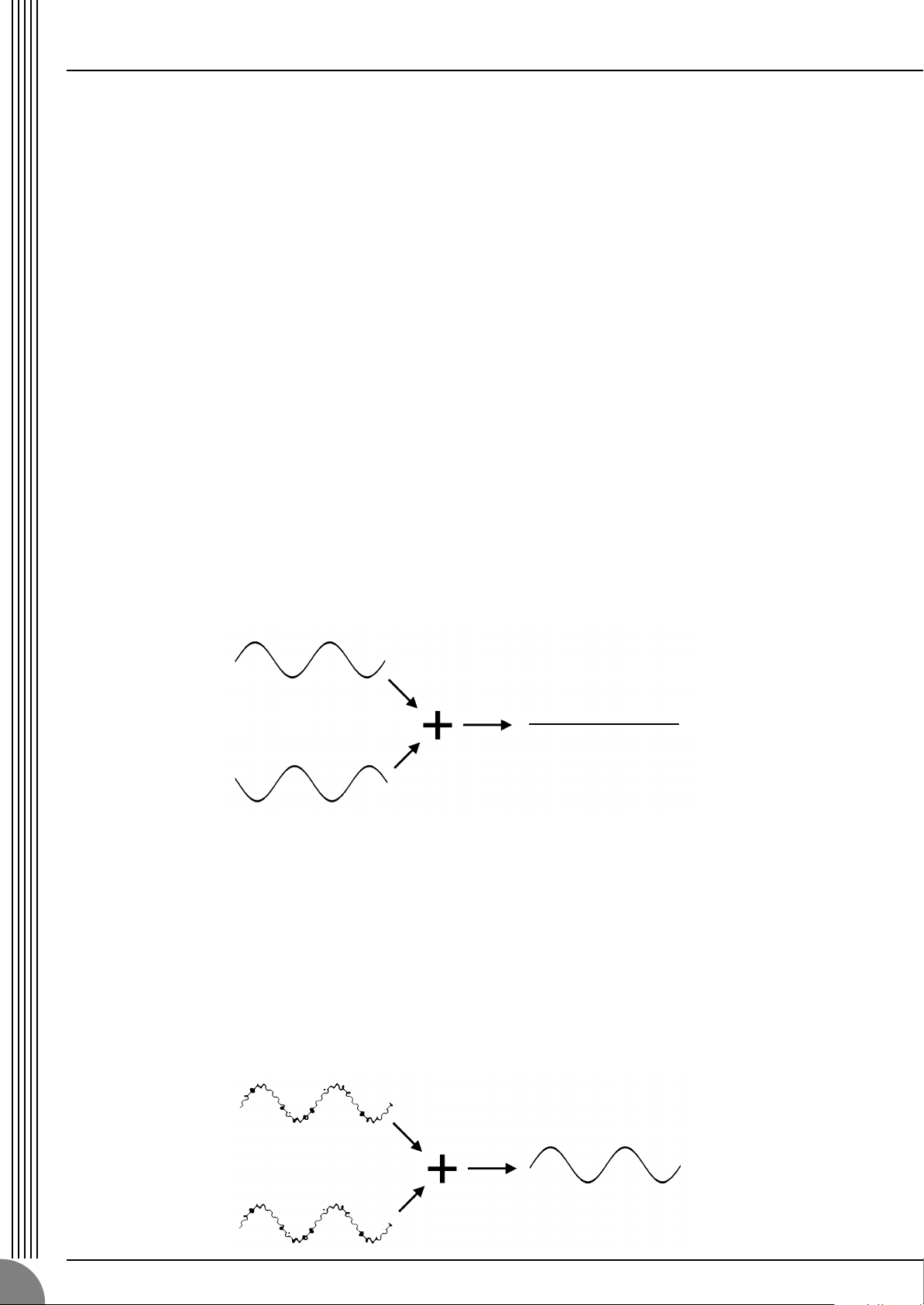
Balanced lines work on the principle of “phase cancellation”: if you add two identical signals out of
phase (i.e. one signal is inverted so its peaks coincide with the troughs in the other signal), the result is …
nothing. A flat line. The signals cancel each other out.
A balanced cable has three conductors:
1) A ground conductor which carries no signal, just the “ground” or “0” reference against which the
signal in the other conductors fluctuates.
2) A “hot” or “+” conductor which carries the normal-phase audio signal.
3) A “cold” or “–” conductor which carries the reverse-phase audio signal.
While the desired audio signals in the hot and cold conductors are out of phase, any noise induced in
the line will be exactly the same in both conductors, and thus in phase. The trick is that the phase of
one signal is reversed at the receiving end of the line so that the desired audio signals become in-
phase, and the induced noise suddenly finds itself out of phase. The out-of-phase noise signal is effec-
tively canceled while the audio signal is left intact. Clever, eh?
Normal-phase signal.
Reverse-phase signal.
No signal.
(Phase cancellation)
Normal-phase signal
+ normal-phase noise.
Normal-phase signal
+ reverse-phase noise.
Desired signal
with no noise.

Making the Most Of Your Mixer
MG16/4, MG12/4
9
1-3. Signal Levels—Decibel Do’s and Don’ts
From the moment you start dealing with things audio, you’ll have to deal with the term “decibel” and its
abbreviation, “dB”. Things can get confusing because decibels are a very versatile unit of measure used
to describe acoustic sound pressure levels as well as electronic signal levels. To make matters worse there
are a number of variations: dBu, dBV, dBm. Fortunately, you don’t need to be an expert to make things
work. Here are a few basics you should keep in mind:
●
“Consumer” gear (such as home audio equipment) usually has line inputs and outputs with a nomi-
nal (average) level of –10 dB.
●
Professional audio gear usually has line inputs and outputs with a nominal level of +4 dB.
●
You should always feed –10 dB inputs with a –10 dB signal. If you feed a +4 dB signal into a –10 dB
input you are likely to overload the input.
●
You should always feed +4 dB inputs with a +4 dB signal. A –10 dB signal is too small for a +4 dB
input, and will result in less-than-optimum performance.
●
Many professional and semi-professional devices have level switches on the inputs and/or outputs
that let you select –10 or +4 dB. Be sure to set these switches to match the level of the connected
equipment.
●
Inputs that feature a “Gain” control—such as the mono-channel inputs on your Yamaha mixer—will
accept a very wide range of input levels because the control can be used to match the input’s sensi-
tivity to the signal. More on this later.
Making the Most Of Your Mixer
MG16/4, MG12/4
10
Where Your Signal Goes Once It’s Inside the Box
At first glance the block diagram of even a modest mixer can look like a space-station schematic. In reality,
block diagrams are a great aid in understanding how the signal flows in any mixer. Here’s a greatly simplified
block diagram of a generic mixer to help you become familiar with the way these things work.
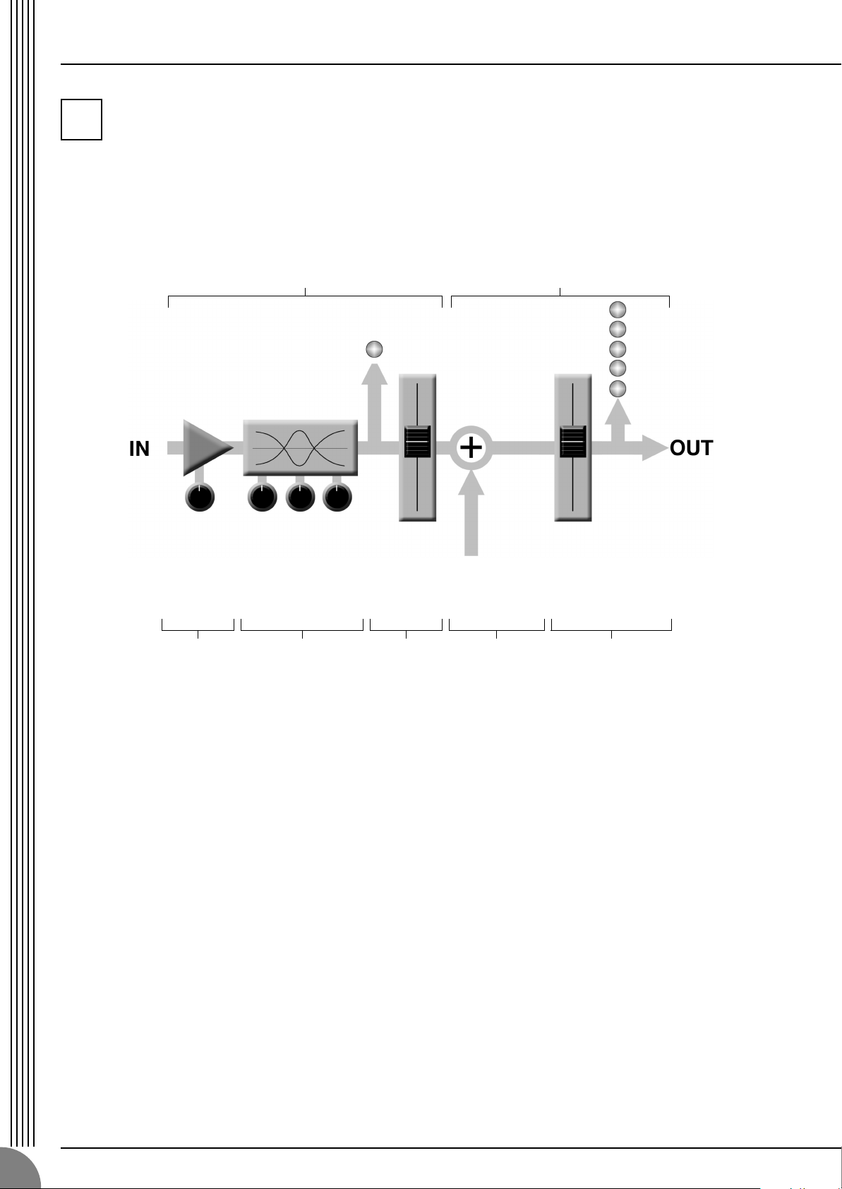
2-1. Greatly Simplified Mixer Block Diagram
■
Input Channel
1
Head Amp
The very first stage in any mixer, and
usually the only stage with significant
“gain” or “amplification.” The head
amp has a “gain” control that adjusts
the mixer’s input sensitivity to match the
level of the source. Small signals (e.g.
mics) are amplified, and large signals
are attenuated.
2
Equalizer
Could be simple bass and treble con-
trols or a full-blown 4-band parametric
EQ. When boost is applied the EQ stage
also has gain. You can actually overload
the input channel by applying too much
EQ boost. It’s usually better to cut than
boost.
3
Channel Peak LED & Fader
The channel peak LED is your most
valuable tool for setting the input “gain”
control for optimum performance. Note
that it is located after the head amp and
EQ stage.
■
Master Section
4
Summing Amplifier
This is where the actual “mixing” takes
place. Signals from all of the mixer’s
input channels are “summed” (mixed)
together here.
5
Master Fader & Level Meter
A stereo, mono, or bus master fader and
the mixer’s main output level meter.
There could be several master faders
depending on the design of the mixer—
i.e. the number of buses or outputs it
provides.
2
1234 5
Input Channel Master Section
Signals from the mixer’s
other input channels (if
they are assigned to this
master output or “bus”).
Loading...