

Page 1
Enterprise System Controller
Release Version: 5.6.2
Page 2

Page 3

Table of Contents
Chapter 1: Software Installation .....................................1
Introduction. . . . . . . . . . . . . . . . . . . . . . . . . . . . . . . . . . . . . . . . . . . . . . . . . . . . . . . . . . . . . . . . . . . . . . 1
System Requirements ............................................................1
Network Topology Requirements .................................................1
Software Installation ..............................................................1
Chapter 2: UniFi Cloud ..............................................5
Introduction. . . . . . . . . . . . . . . . . . . . . . . . . . . . . . . . . . . . . . . . . . . . . . . . . . . . . . . . . . . . . . . . . . . . . . 5
UniFi Cloud Key ..................................................................5
UniFi Cloud Account .............................................................13
Chapter 3: Using the UniFi Controller Software .....................17
Navigation Bar ..................................................................17
Common Interface Options ......................................................17
Table of ContentsUniFi Controller User Guide
Chapter 4: Dashboard .............................................63
Latency .........................................................................63
Throughput .....................................................................63
WAN ............................................................................64
LAN .............................................................................64
WLAN ...........................................................................65
Download Throughput & Latency ................................................65
Upload Throughput & Latency ...................................................65
Devices on 2.4 GHz Radio Band ..................................................66
Devices on 5 GHz Radio Band ....................................................66
Clients on 2.4 GHz Radio Band ...................................................67
Clients on 5 GHz Radio Band .....................................................67
Devices .........................................................................68
Clients ..........................................................................68
Deep Packet Inspection ..........................................................68
Dynamic Dashboard (beta) ......................................................69
Chapter 5: Statistics ...............................................71
Overview ........................................................................71
Traffic Stats ......................................................................73
Performance ....................................................................76
Switch Stats .....................................................................77
Speed Test Stats .................................................................78
Debugging Metrics ..............................................................78
Ubiquiti Networks, Inc.
i
Page 4

Table of Contents UniFi Controller User Guide
Chapter 6: Map ....................................................81
Adding Custom Maps. . . . . . . . . . . . . . . . . . . . . . . . . . . . . . . . . . . . . . . . . . . . . . . . . . . . . . . . . . . .81
Adding a Google Map ...........................................................82
Editing a Map ...................................................................83
Placing Devices on the Map ......................................................84
Device Information ..............................................................84
Map Display Options ............................................................85
Drawing Walls ...................................................................87
Setting the Map Scale ...........................................................87
System Topology ................................................................88
Chapter 7: Devices ................................................89
All ...............................................................................91
Gateway/Switches ...............................................................92
APs .............................................................................95
Chapter 8: Clients .................................................99
All ............................................................................. 102
Wireless ....................................................................... 103
Wired ......................................................................... 104
Chapter 9: Insights ...............................................105
Neighboring Access Points .................................................... 106
Known Clients ................................................................. 106
Past Connections .............................................................. 107
Past Guest Authorizations ..................................................... 108
Switch Stats ................................................................... 108
Port Forward Stats ............................................................. 111
Dynamic DNS ................................................................. 113
Remote User VPN .............................................................. 113
AC-EDU Streams ............................................................... 114
Controller Logs ................................................................ 114
Chapter 10: UniFi Security Gateway Details .......................115
Properties ..................................................................... 115
UniFi Security Gateway – Details ............................................... 116
UniFi Security Gateway – Networks ............................................ 117
UniFi Security Gateway – Configuration ........................................ 117
Chapter 11: UniFi Switch Details ..................................121
Properties
UniFi Switch – Details
UniFi Switch – Users ........................................................... 123
UniFi Switch – Guests .......................................................... 123
UniFi Switch – Ports ........................................................... 124
UniFi Switch – Configuration
..................................................................... 121
.......................................................... 122
................................................... 127
ii
Ubiquiti Networks, Inc.
Page 5

Chapter 12: UniFi Access Point Details ............................131
Properties ..................................................................... 131
UniFi Access Point – Details .................................................... 132
UniFi Access Point – Guests .................................................... 134
UniFi Access Point – Configuration ............................................. 135
UniFi Access Point – Tools ...................................................... 141
Chapter 13: Client Details .........................................147
Properties ..................................................................... 147
Wireless Client – Details ....................................................... 147
Wireless Client – History .......................................................148
Wireless Client – Configuration ................................................ 148
Wired Client – Details .......................................................... 149
Wired Client – Statistics ........................................................ 149
Wired Client – History ......................................................... 150
Wired Client – Configuration ................................................... 150
Table of ContentsUniFi Controller User Guide
Chapter 14: Hotspot Manager ....................................151
Analytics ...................................................................... 152
Guests ........................................................................ 152
Payments and Transactions .................................................... 153
Vouchers ...................................................................... 154
Operator Accounts ............................................................ 155
Appendix A: Portal Customization with LegacyJSP ................157
Before You Begin .............................................................. 157
Overview ...................................................................... 157
Configuring Portal Customization .............................................. 157
Viewing the Default Portal ..................................................... 158
Setup ......................................................................... 158
Appendix B: UniFi Mobile App ....................................161
Overview ...................................................................... 161
Standalone Mode .............................................................161
Controller Mode ............................................................... 164
Appendix C: Controller Scenarios .................................165
Overview ...................................................................... 165
Hosting Controller Software ................................................... 165
Deployment Options .......................................................... 165
Layer-3 Adoption
.............................................................. 168
Appendix D: Contact Information .................................171
Ubiquiti Networks, Inc.
Ubiquiti Networks Support .................................................... 171
iii
Page 6

Table of Contents UniFi Controller User Guide
iv
Ubiquiti Networks, Inc.
Page 7
Chapter 1: Software InstallationUniFi Controller User Guide
UAP-AC-M-PRO
Remote Access to
UniFi Controller
Chapter 1: Software Installation
Introduction
Thank you for purchasing the Ubiquiti Networks® UniFi®
Enterprise System. The UniFi devices are bundled with the
UniFi Controller software, which allows you to manage
your UniFi network using a web browser.
This User Guide is for use with version 5.6.2 or above of the
UniFi Controller software.
System Requirements
• Linux, MacOSX 10.11 (or above), or Microsoft
Windows7/8/10
• Java Runtime Environment 1.8 or above recommended
• Web Browser: Google Chrome (Other browsers may
have limited functionality.)
Network Topology Requirements
• A DHCP-enabled network (so any device can obtain an
IP address)
• One of the following:
• UniFi Cloud Key
• A management station running the UniFi Controller
software, located either on-site and connected to the
same Layer-2 network, or off-site* in a cloud or NOC
• For the public address system capability of the
UAP-AC-EDU: A compatible Android™ or iOS device
located on the same Layer-2 network as the UniFi
Controller and UniFi APs
All UniFi devices support off-site management controllers.
Follow the instructions in this chapter after you install the
hardware, which is described in the Quick Start Guide.
Software Installation
Download the latest version of the UniFi Controller
software at downloads.ubnt.com/unifi
Follow the instructions for your specific computer or
device type.
UniFi Cloud Key Users
If you have the UniFi Cloud Key, please refer to “UniFi
Cloud Key” on page 5 for more information.
UniFi Cloud Users
If you have a UniFi cloud account, please refer to “UniFi
Cloud Account” on page 13 for more information.
Linux Users
Please refer to the UniFi blog on our community site at:
http://ubnt.link/UniFi-Blog
Mac Users
1. Launch UniFi.pkg.
2. Click Continue and follow the on-screen instructions to
install the software.
* Requires Layer-3 adoption. For details, refer to:
http://ubnt.link/UniFi-Layer3-Adoption
Ubiquiti Networks, Inc.
UniFi Hybrid
Cloud Install
CURRENT SITE
Default
25 22
547
597
2 118
WAN
LAN WLAN
2290.2
0.9 116
7 0.94 1
7
0.01 413
ACTIVE DEVICE
ACTIVE DEVICES
2.33
200+0 700+0
Inacve 0
Inacve 0
msec Mbps
Pending
0
Pending 0
LATENCY THROUGHPUT
SPEED TEST
DOWNLOAD THROUGHPUT & LATENCY
DEVICES ON 2.4 GHZ CHANNEL
10
250
Latency [msec]
8
200
6
150
1 2 3 4 5 6 7 8 9 10 11
4
100
2
50
Throughput [Mbps]
DEVICES ON 5 GHZ CHANNEL
0
0
24 HRS 12 HRS NOW
Avg/Max Throughput Latency
UPLOAD THROUGHPUT & LATENCY
36 40 44 48 52 56 60 64
10
100
Latency [msec]
8
80
100 104 108 112 116 120 124 128
6
60
4
40
2
20
Throughput [Mbps]
132 136 140 144 149 153 157 161 165
0
0
24 HRS 12 HRS NOW
DEEP PACKET INSPECTIONCLIENTSDEVICES
Network Protocols
Motorola
258
Streaming Media
Lenovo
241
WLAN
118
Web / Web 2.0
SamsungE
220
126
645 GB
1172
LAN
7
File Transfer
Dell
213
DEVICES
TRAFFIC
CLIENTS
WAN
1
Social Network
Acer
130
Other
Other
110
US-16-150W
USG-PRO-4
(DHCP Server)
25 22
547
597
2 118
WAN
LAN WLAN
2290.2
0.9 116
7 0.94 1
7
0.01 413
ACTIVE DEVICE
ACTIVE DEVICES
2.33
200+0 700+0
Inacve 0
Inacve 0
msec Mbps
LATENCY THROUGHPUT
Pending
0
Pending 0
SPEED TEST
DOWNLOAD THROUGHPUT & LATENCY DEVICES ON 2.4 GHZ CHANNEL
250
10
Latency [msec]
200
8
150
6
1 2 3 4 5 6 7 8 9 10 11
100
4
50
2
Throughput [Mbps]
DEVICES ON 5 GHZ CHANNEL
0
0
24 HRS 12 HRS NOW
Avg/Max Throughput Latency
UPLOAD THROUGHPUT & LATENCY
36 40 44 48 52 56 60 64
100
10
Latency [msec]
80
8
100 104 108 112 116 120 124 128
60
6
40
4
20
2
Throughput [Mbps]
132 136 140 144 149 153 157 161 165
0
0
24 HRS 12 HRS NOW
DEEP PACKET INSPECTIONCLIENTSDEVICES
Network Protocols
Motorola
258
Streaming Media
Lenovo
241
WLAN
118
Web / Web 2.0
SamsungE
220
126
645 GB
1172
LAN
7
File Transfer
Dell
213
DEVICES
TRAFFIC
CLIENTS
WAN
1
Social Network
Acer
130
Other
Other
110
USERNAME
admin
118
ACTIVE DEVICES
Inacve 0
Pending
UAP-AC-HD
0
582 GB
23.3 GB
22.7 GB
8.47 GB
3.6 GB
5.46 GB
UAP-AC-PRO
3. Go to Go > Applications and double-click the UniFi
icon.
LAN
WAN
Internet
CURRENT SITE
USERNAME
Default
admin
118
ACTIVE DEVICES
Inacve 0
Pending
0
582 GB
23.3 GB
22.7 GB
8.47 GB
3.6 GB
5.46 GB
Proceed to “Configuring the UniFi Controller Software”
on page 2.
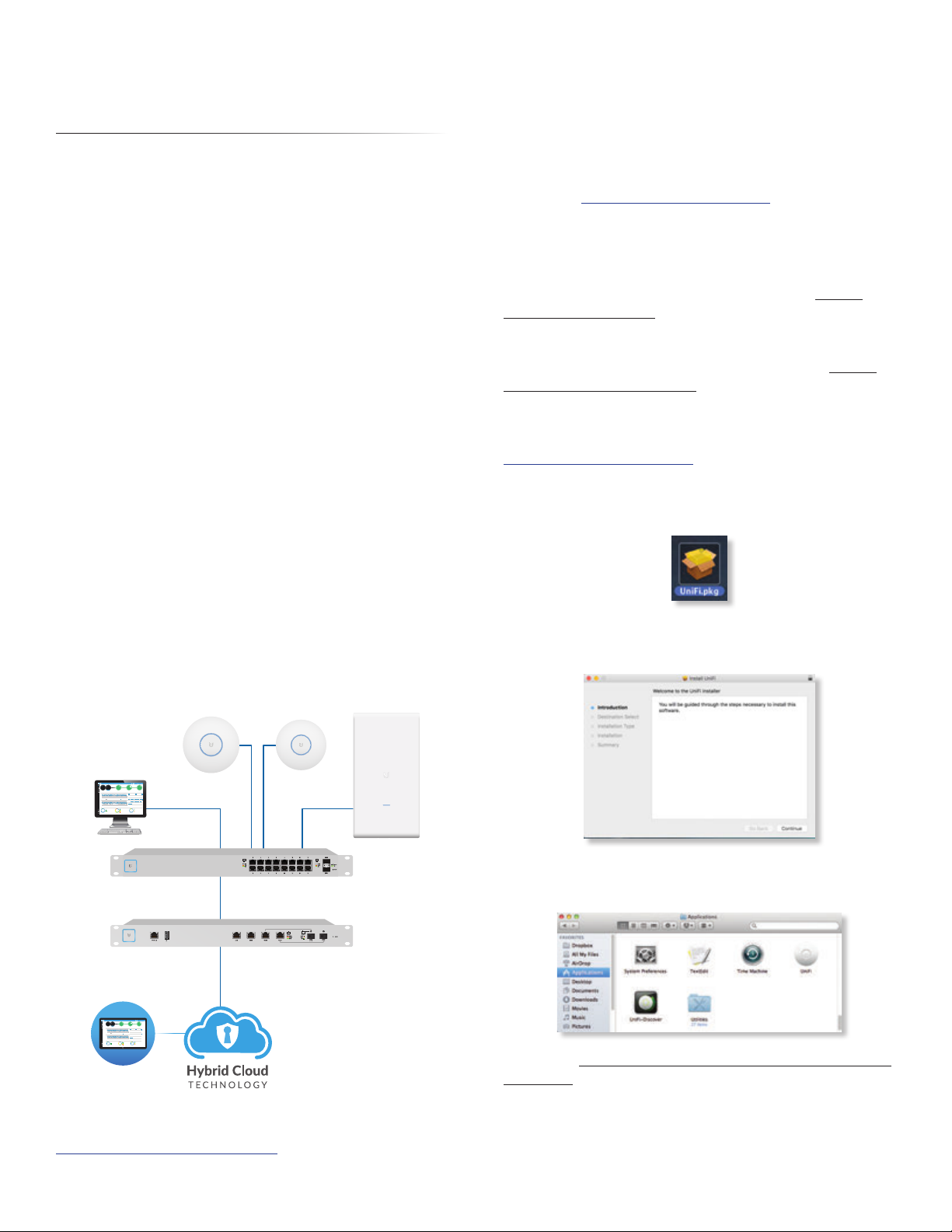
Sample Network Diagram
1
Page 8
Chapter 1: Software Installation UniFi Controller User Guide
PC Users
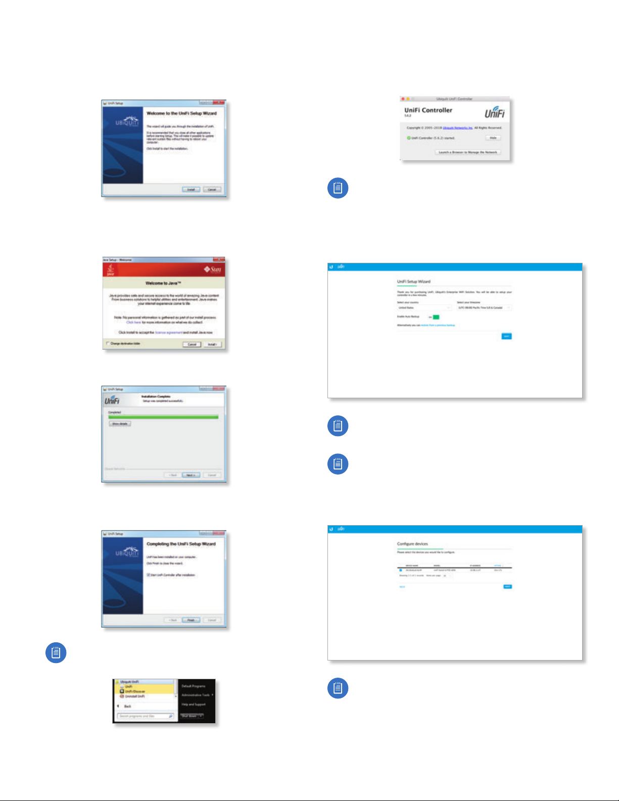
1. Launch UniFi-installer.exe.
2. Click Install.
3. If your computer doesn’t have Java 1.6 or above
installed, you will be prompted to install it. Click Install
to continue.
Configuring the UniFi Controller Software
1. The UniFi Controller software startup will begin. Click
Launch a Browser to Manage Wireless Network.
Note: The above applies to Windows and OS X only.
On Linux, open a browser and go to the following
URL: https://<IP_address_of_controller>:8443
2. Select your country and time zone. Alternatively, you
can click restore from a previous backup to use a file
that contains your backup settings. Click Next.
4. Click Next.
5. Ensure that the Start UniFi Controller after installation
option is checked and click Finish.
Note: The UniFi Controller software can also be
launched from Start > All Programs.
Note: Enable Auto Backup is on by default. Toggle
off if you wish to disable.
Note: U.S. product versions are locked to the U.S.
Country Code to ensure compliance with FCC
regulations.
3. Select the devices that you want to configure and
clickNext.
Note: If there is more than one page of entries
to display, click the navigation controls or page
numbers at the bottom right of the screen to display
different pages.
2
Ubiquiti Networks, Inc.
Page 9
Chapter 1: Software InstallationUniFi Controller User Guide
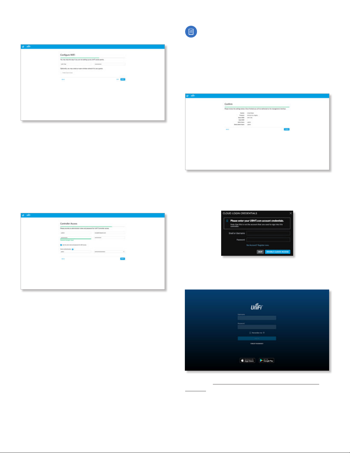
4. The UniFi Setup Wizard will create a secure primary
wireless network for your devices.
Perform the following steps:
a. Enter the wireless network name (SSID) in the Secure
SSID field.
b. Enter a passphrase to be used for your primary
network in the Security Key field.
c. To enable guest access, select Enable Guest Access,
and enter a guest network name in the Guest
SSIDfield.
d. Click Next.
5. Create the superadmin for your UniFi Controller.
Note: Only the superadmin and admins who have
permission to adopt devices can view devices
that are Pending Approval and then adopt them
on the UniFi Controller. Ensure that you save the
superadmin login information for futureuse.
6. Review your settings. Click Finish to save your settings
or click Back to make changes. Once the wizard is
finished, the browser will be redirected to the Cloud
Login Credentials screen.
7. Enter your Ubiquiti account email/username and
password to enable cloud access. Alternatively, you can
click Register now to create a Ubiquiti account. Click
Enable Cloud Access.
Perform the following steps:
a. Enter an admin name in the Admin Name field.
b. Enter an email address in the Admin Email field.
c. Enter a password in the Password field to use
when accessing the management interface as a
superadmin.
d. Confirm your password in the Confirm Password
field.
e. To use the same login for SSH access, select Use the
same name and password for SSH access.
f. To set up a separate login for SSH access, enter
an admin name and password for the Device
Authentication fields.
g. Click Next.
8. A login screen will appear for the UniFi Controller
management interface. Enter the admin name and
password that you created and click Sign In.
Proceed to “Using the UniFi Controller Software” on
page 17 for information on using the UniFi Controller
software.
Ubiquiti Networks, Inc.
3
Page 10

Chapter 1: Software Installation UniFi Controller User Guide
4
Ubiquiti Networks, Inc.
Page 11

Chapter 2: UniFi CloudUniFi Controller User Guide
UAP-AC-M-PRO
Remote Access to
UniFi Controller
Chapter 2: UniFi Cloud
Introduction
You can access the UniFi Controller via the UniFi Cloud Key
and/or the UniFi cloud account. This chapter describes the
following:
• UniFi Cloud Key
• “UniFi Cloud Account” on page 13
UniFi Cloud Key
The UniFi Cloud Key includes the pre-installed UniFi
Controller software.
System Requirement
Web Browser: Google Chrome (Other browsers may have
limited functionality.)
Network Topology Requirement
A DHCP-enabled network (for the UniFi Cloud Key to
obtain an IP address)
UniFi Hybrid
Cloud Install
CURRENT SITE
USERNAME
Default
admin
25 22
547
597
2 118
WAN
LAN WLAN
2290.2
0.9 116
7 0.94 1
0.01 413
2.33
200+0 700+0
msec Mbps
LATENCY THROUGHPUT
SPEED TEST
DOWNLOAD THROUGHPUT & LATENCY
250
200
150
100
50
Throughput [Mbps]
0
24 HRS 12 HRS NOW
Avg/Max Throughput Latency
UPLOAD THROUGHPUT & LATENCY
100
80
60
40
20
Throughput [Mbps]
0
24 HRS 12 HRS NOW
WLAN
126
LAN
DEVICES
WAN
7
118
ACTIVE DEVICE
ACTIVE DEVICES
ACTIVE DEVICES
Inacve 0
Inacve 0
Inacve 0
Pending
Pending
0
Pending 0
DEVICES ON 2.4 GHZ CHANNEL
10
Latency [msec]
8
6
1 2 3 4 5 6 7 8 9 10 11
4
2
DEVICES ON 5 GHZ CHANNEL
0
36 40 44 48 52 56 60 64
10
Latency [msec]
8
100 104 108 112 116 120 124 128
6
4
2
132 136 140 144 149 153 157 161 165
0
DEEP PACKET INSPECTIONCLIENTSDEVICES
Network Protocols
Motorola
258
Streaming Media
Lenovo
241
118
Web / Web 2.0
SamsungE
220
645 GB
1172
7
File Transfer
Dell
213
TRAFFIC
CLIENTS
1
Social Network
Acer
130
Other
Other
110
UAP-AC-HD
0
582 GB
23.3 GB
22.7 GB
8.47 GB
3.6 GB
5.46 GB
UAP-AC-PRO
Chrome Instructions
1. Ensure that your host system is on the same Layer-2
network as the UniFi CloudKey.
2. Launch the Chrome web browser and type
https://unifi.ubnt.com in the address field. Press enter
(PC) or return (Mac).
https://unifi.ubnt.com
3. Enter the username and password for your UBNT
account. Click Sign In.
4. Click Discover Cloud Key.
US-16-150W
LAN
USG-PRO-4
WAN
(DHCP Server)
Internet
CURRENT SITE
USERNAME
Default
admin
25 22
547
597
2 118
WAN
LAN WLAN
2290.2
0.9 116
7 0.94 1
7
118
0.01 413
ACTIVE DEVICE
ACTIVE DEVICES
ACTIVE DEVICES
2.33
200+0 700+0
Inacve 0
Inacve 0
Inacve 0
msec Mbps
LATENCY THROUGHPUT
Pending
Pending
0
Pending 0
0
SPEED TEST
DOWNLOAD THROUGHPUT & LATENCY DEVICES ON 2.4 GHZ CHANNEL
250
10
Latency [msec]
200
8
150
6
1 2 3 4 5 6 7 8 9 10 11
100
4
50
2
Throughput [Mbps]
DEVICES ON 5 GHZ CHANNEL
0
0
24 HRS 12 HRS NOW
Avg/Max Throughput Latency
UPLOAD THROUGHPUT & LATENCY
36 40 44 48 52 56 60 64
100
10
Latency [msec]
80
8
100 104 108 112 116 120 124 128
60
6
40
4
20
2
Throughput [Mbps]
132 136 140 144 149 153 157 161 165
0
0
24 HRS 12 HRS NOW
DEEP PACKET INSPECTIONCLIENTSDEVICES
Network Protocols
Motorola
582 GB
258
Streaming Media
Lenovo
23.3 GB
241
WLAN
118
Web / Web 2.0
SamsungE
22.7 GB
220
126
645 GB
1172
LAN
7
File Transfer
Dell
8.47 GB
213
DEVICES
TRAFFIC
CLIENTS
WAN
1
Social Network
Acer
3.6 GB
130
Other
Other
5.46 GB
110
Sample Network Diagram
Software Installation
After you follow the hardware installation instructions
in the UniFi Cloud Key Quick Start Guide, use one of the
following methods to launch the software:
• If you are using Chrome, go to the Chrome Instructions
section (recommended).
• If you are using a different web browser, go to
“Instructions for Other Web Browsers” on page 7.
Note: The default fallback IP address of the UniFi
Cloud Key is 192.168.1.30.
5. If the Ubiquiti® Device Discovery Tool is already
installed, proceed to step 7.
If the tool is not installed, you will be prompted to add
it. Proceed to step 6.
Ubiquiti Networks, Inc.
5
Page 12
Chapter 2: UniFi Cloud UniFi Controller User Guide
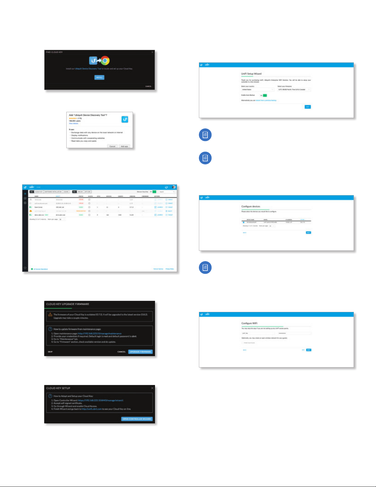
6. To install the tool:
a. Click Install.
b. Click Add app to confirm.
7. The Ubiquiti Device Discovery Tool will search for the
UniFi Cloud Key. Click Adopt in the Cloud Key’s Actions
column to continue.
10. The UniFi Setup Wizard screen appears. Select your
country and time zone. Alternatively, you can click
restore from a previous backup to use a file that
contains your backup settings. Click Next.
Note: Enable Auto Backup is on by default. Toggle
off if you wish to disable.
Note: U.S. product versions are locked to the U.S.
Country Code to ensure compliance with FCC
regulations.
11. Select the devices that you want to configure and
clickNext.
8. If the Cloud Key firmware is not the latest version, click
Upgrade Firmware to upgrade the firmware.
9. Click Open Controller Wizard to set up the Controller
on the Cloud Key.
Note: If there is more than one page of entries
to display, click the navigation controls or page
numbers at the bottom right of the screen to display
different pages.
12. The UniFi Setup Wizard will create a secure primary
wireless network for your devices.
Perform the following steps:
a. Enter the wireless network name (SSID) in the Secure
SSID field.
b. Enter a passphrase to be used for your primary
network in the Security Key field.
c. To enable guest access, select Enable Guest Access,
and enter a guest network name in the Guest
SSIDfield.
d. Click Next.
6
Ubiquiti Networks, Inc.
Page 13
Chapter 2: UniFi CloudUniFi Controller User Guide
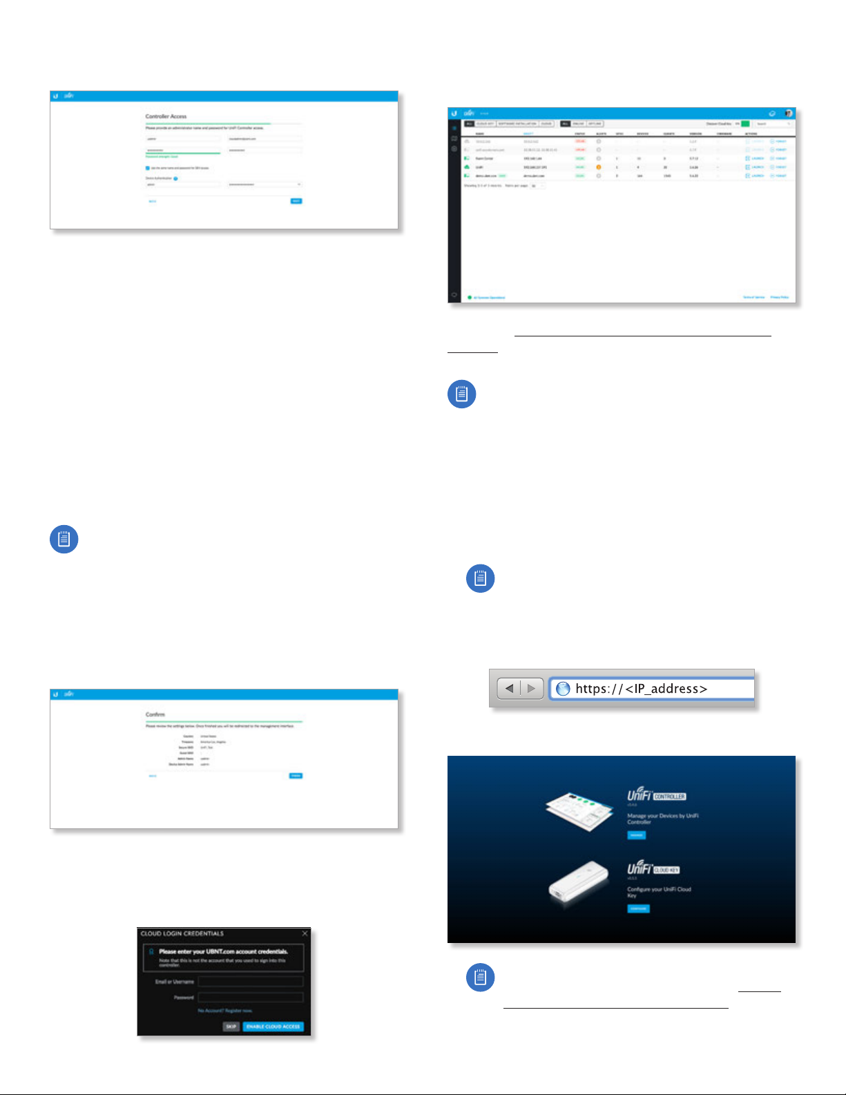
13. Create the superadmin for your UniFi Controller.
Perform the following steps:
a. Enter an admin name in the Admin Name field.
b. Enter an email address in the Admin Email field.
c. Enter a password in the Password field to use
when accessing the management interface as a
superadmin.
d. Confirm your password in the Confirm Password
field.
e. To use the same login for SSH access, select Use the
same name and password for SSH access.
f. To set up a separate login for SSH access, enter
an admin name and password for the Device
Authentication fields.
g. Click Next.
Note: Only the superadmin and admins who have
permission to adopt devices can view devices
that are Pending Approval and then adopt them
on the UniFi Controller. Ensure that you save the
superadmin login information for futureuse.
14. Review your settings. Click Finish to save your settings
or click Back to make changes. Once the wizard is
finished, the browser will be redirected to the Cloud
Login Credentials screen.
16. Wait for the UniFi Controller to be adopted, and then
click Launch.
Proceed to “Using the UniFi Controller Software” on
page 17 for information on using the UniFi Controller
software.
Note: A future feature will enable backup of the
UniFi Controller database and configuration on the
included microSD card.
Instructions for Other Web Browsers
1. Ensure that your host system is on the same Layer-2
network as the UniFi CloudKey.
2. The UniFi Cloud Key is set to DHCP by default, so it
will try to automatically obtain an IP address. Assign a
specific IP address to the UniFi Cloud Key, or check the
DHCP server for its IP address.
Note: The default fallback IP address of the UniFi
Cloud Key is 192.168.1.30.
3. Launch the web browser. In the address field, type
https:// followed by the appropriate IP address. Press
enter (PC) or return (Mac).
15. Enter your Ubiquiti account email/username and
password to enable cloud access. Alternatively, you can
click Register now to create a Ubiquiti account. Click
Enable Cloud Access.
Ubiquiti Networks, Inc.
4. Click Manage to run the UniFi Setup Wizard.
Note: You can click Configure to change the
settings of the UniFi Cloud Key (refer to “UniFi
Cloud Key Configuration” on page 9 for
more information). The default login is ubnt/ubnt
or root/ubnt.
7
Page 14

Chapter 2: UniFi Cloud UniFi Controller User Guide
5. The UniFi Setup Wizard screen appears. Select your
country and time zone. Alternatively, you can click
restore from a previous backup to use a file that
contains your backup settings. Click Next.
Note: Enable Auto Backup is on by default. Toggle
off if you wish to disable.
Note: U.S. product versions are locked to the U.S.
Country Code to ensure compliance with FCC
regulations.
6. Select the devices that you want to configure and
clickNext.
8. Create the superadmin for your UniFi Controller.
Perform the following steps:
a. Enter an admin name in the Admin Name field.
b. Enter an email address in the Admin Email field.
c. Enter a password in the Password field to use
when accessing the management interface as a
superadmin.
d. Confirm your password in the Confirm Password
field.
e. To use the same login for SSH access, select Use the
same name and password for SSH access.
f. To set up a separate login for SSH access, enter
an admin name and password for the Device
Authentication fields.
g. Click Next.
Note: If there is more than one page of entries
to display, click the navigation controls or page
numbers at the bottom right of the screen to display
different pages.
7. The UniFi Setup Wizard will create a secure primary
wireless network for your devices.
Perform the following steps:
a. Enter the wireless network name (SSID) in the Secure
SSID field.
b. Enter a passphrase to be used for your primary
network in the Security Key field.
c. To enable guest access, select Enable Guest Access,
and enter a guest network name in the Guest
SSIDfield.
d. Click Next.
Note: Only the superadmin and admins who have
permission to adopt devices can view devices
that are Pending Approval and then adopt them
on the UniFi Controller. Ensure that you save the
superadmin login information for futureuse.
9. Review your settings. Click Finish to save your settings
or click Back to make changes. Once the wizard is
finished, the browser will be redirected to the Cloud
Login Credentials screen.
10. Enter your Ubiquiti account email/username and
password to enable cloud access. Alternatively, you can
click Register now to create a Ubiquiti account. Click
Enable Cloud Access.
8
Ubiquiti Networks, Inc.
Page 15

Chapter 2: UniFi CloudUniFi Controller User Guide
A login screen will appear for the UniFi Controller
management interface. Enter the admin name and
password that you created and click Login.
Proceed to “Using the UniFi Controller Software” on
page 17 for information on using the UniFi Controller
software.
Note: You can back up the UniFi Controller database
and configuration on the included microSD card.
UniFi Cloud Key Configuration
Login Instructions
1. Ensure that your host system is on the same Layer-2
network as the UniFi CloudKey.
2. The UniFi Cloud Key is set to DHCP by default, so it
will try to automatically obtain an IP address. Assign a
specific IP address to the UniFi Cloud Key, or check the
DHCP server for its IP address.
Note: The default fallback IP address of the UniFi
Cloud Key is 192.168.1.30.
4. You have two options:
• Manage Click Manage to access the UniFi
Controller. Proceed to “Using the UniFi Controller
Software” on page 17 for more information.
• Configure Click Configure to change the settings of
the UniFi Cloud Key.
5. After you click Configure, enter the Username and
Password (the default login is ubnt/ubnt). Then click
Login.
3. Launch the web browser. In the address field, type
https:// followed by the appropriate IP address. Press
enter (PC) or return (Mac).
The Main screen will appear.
Ubiquiti Networks, Inc.
9
Page 16
Chapter 2: UniFi Cloud UniFi Controller User Guide
Navigation Bar
The UniFi Cloud Key configuration consists of three
primary pages:
• “Main” on page 10
• “Configuration” on page 11
• “Maintenance” on page 12
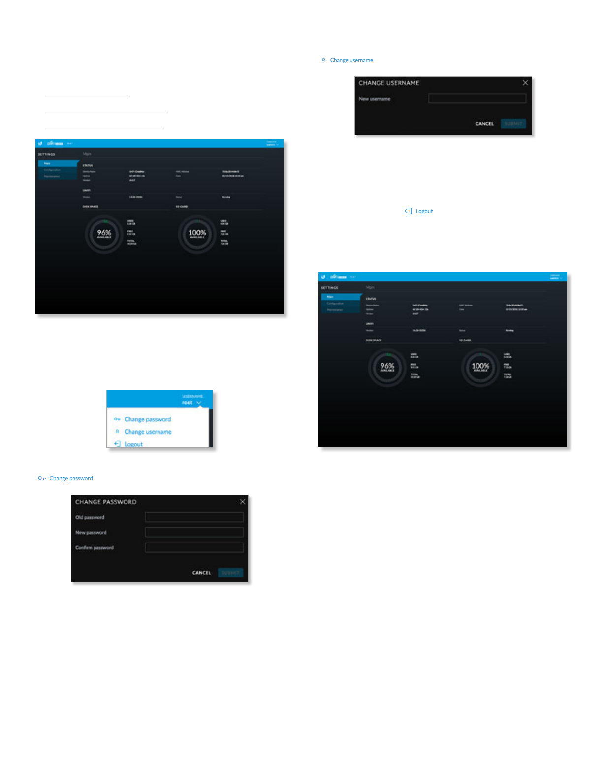
Change username To change the username, click
. The Change Username screen will appear:
• New password Enter the new username.
• Submit Click Submit to apply changes.
• Cancel Click Cancel to discard changes.
Logout To manually sign out of the UniFi Cloud Key
configuration, click .
Main
The Main screen displays basic status information about
the UniFi Cloud Key.
Username
At the top right of each screen, click the Username to
display the Change Password, Change Username, and
Logout options:
Change password To change the password, click
. The Change Password screen will appear:
• Old password Enter the current password (the default
is ubnt).
• New password Enter the new password.
• Confirm password Enter the new password again.
• Submit Click Submit to apply changes.
• Cancel Click Cancel to discard changes.
Status
Device Name Displays the hostname or alias of the UniFi
Cloud Key.
Uptime Displays the duration of time the UniFi Cloud Key
has been running.
Version Displays the version number of the UniFi Cloud
Key firmware.
MAC Address Displays the MAC address or hardware
identifier of the UniFi Cloud Key.
Date Displays the current date and time.
UniFi
Version Displays the version number of the UniFi
Controller software.
Status Displays the status of the UniFi Controller
software.
Disk Space
Available Displays the percentage of available disk space.
Used Displays the amount of used disk space.
10
Ubiquiti Networks, Inc.
Page 17
Free Displays the amount of available disk space.
Total Displays the total amount of disk space.
SD Card
Available Displays the percentage of available space on
the SD card.
Used Displays the amount of used space on the SD card.
Free Displays the amount of available space on the SD
card.
Total Displays the total amount of space on the SD card.
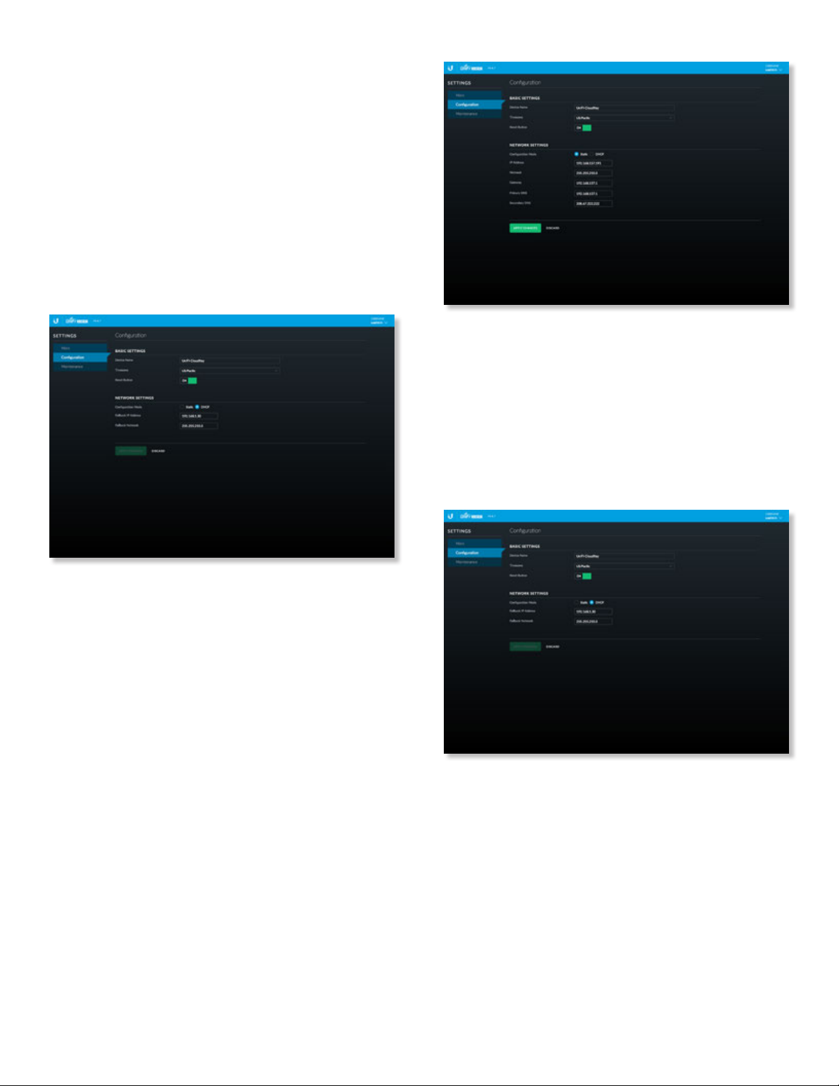
Configuration
The Configuration screen allows you to configure the basic
and network settings of the UniFi Cloud Key.
Chapter 2: UniFi CloudUniFi Controller User Guide
• DHCP The use of the Dynamic Host Configuration
Protocol (DHCP) is the default. The UniFi Cloud Key
automatically acquires network settings from the
network’s DHCP server.
- Fallback IP Address Enter the IP address for the UniFi
Cloud Key to use if an external DHCP server is not
found.
- Fallback Netmask Enter the netmask for the UniFi
Cloud Key to use if an external DHCP server is not
found.
Basic Settings
Device Name Enter a descriptive name or identifier for
the UniFi Cloud Key. Also known as a host name.
Time Zone Select the appropriate time zone.
Reset Button Use of the hardware Reset button on the
UniFi Cloud Key is enabled by default. To prevent an
accidental reset to default settings, click to toggle Off.
Network Settings
Configuration Mode Select the appropriate mode: Static
for fixed settings or DHCP for automatic configuration by
your DHCP server.
• Static Enter the following information:
- IP Address Enter the local IP address of the UniFi
Cloud Key.
- Netmask Enter the subnet mask of the UniFi Cloud
Key.
- Gateway Enter the IP address of the network’s
gateway router.
- Primary DNS Enter the IP address of the network’s
primary DNS server.
- Secondary DNS Enter the IP address of the network’s
secondary DNS server.
Apply Changes Click Apply Changes to save changes.
Discard Click Discard to cancel changes.
Ubiquiti Networks, Inc.
11
Page 18
Chapter 2: UniFi Cloud UniFi Controller User Guide
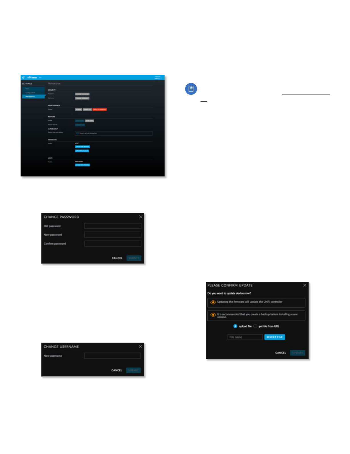
Maintenance
The Maintenance screen contains administrative options,
so you can change the password, reboot the UniFi Cloud
Key, power it off, reset it to factory defaults, restore the
UniFi Controller software, upgrade the UniFi Cloud Key
firmware, or upgrade the UniFi Controller software.
Security
Password To change the password, click Change
Password. The Change Password screen will appear:
• Old password Enter the current password (the default
is ubnt).
• New password Enter the new password.
• Confirm Password Enter the new password again.
• Submit Click Submit to apply changes.
• Cancel Click Cancel to discard changes.
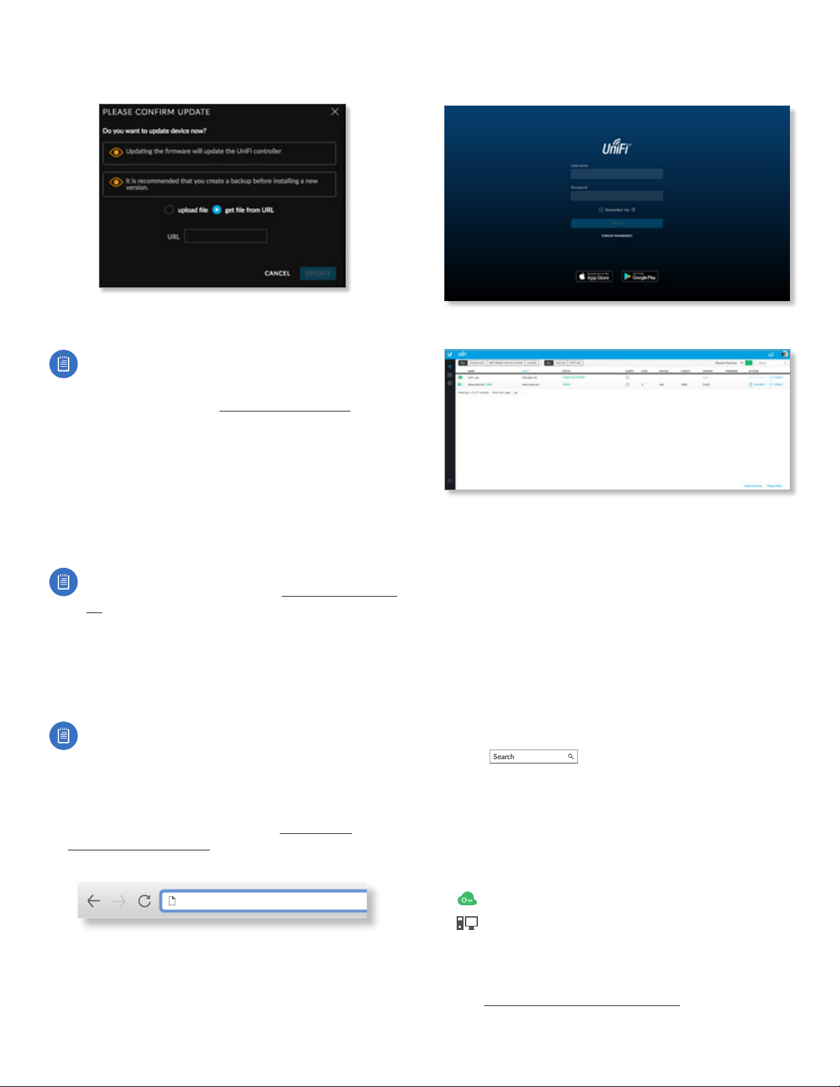
Username To change the username, click Change
Username. The Change Username screen will appear:
Maintenance
Reboot Click Reboot to powercycle the UniFi Cloud Key.
Power Off Click Power Off to turn off the UniFi Cloud Key.
Reset to Defaults Click Reset to Defaults to reset the
UniFi Cloud Key to its factory default settings. This option
will reboot the UniFi Cloud Key, and all factory default
settings will be restored.
Note: We recommend that you back up your UniFi
Controller configuration (refer to “Backup” on page
60 for more information) before resetting the
UniFi Cloud Key to its defaults.
Restore
Service While the UniFi Controller software is running,
click Stop UniFi to stop it. To restart the software, click
Start UniFi to restart it.
Restore from file Click Choose File to restore the UniFi
Controller from a file you specify. Follow the on-screen
instructions.
Auto Backup
Restore from Auto Backup Click to restore from the
automatic backup file. Follow the on-screen instructions.
Firmware
Version Displays the version number of the UniFi Cloud
Key firmware.
Check for Updates Click Check for Updates to see if
there is a newer firmware version. If there is, then you can
follow the on-screen instructions to upgrade now.
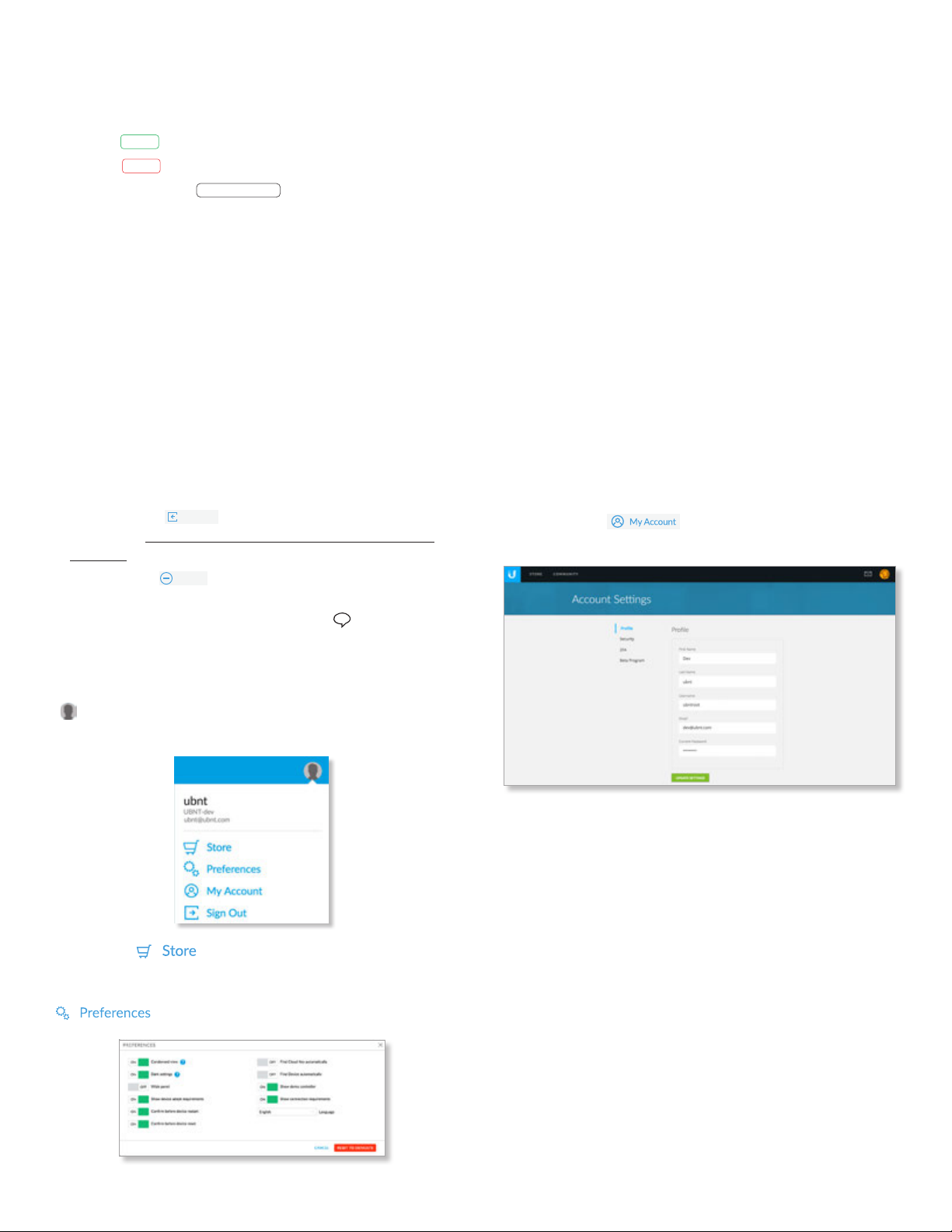
Update Manually Click Update Manually to update the
firmware. The Please Confirm Update screen will appear.
You have two options:
• upload file If you have the firmware saved in a specific
location, then click Select File to browse for the file.
• New username Enter the new username.
• Submit Click Submit to apply changes.
• Cancel Click Cancel to discard changes.
12
Ubiquiti Networks, Inc.
Page 19
Chapter 2: UniFi CloudUniFi Controller User Guide
• get file from URL If you know the URL of the firmware’s
location, then enter it in the URL field.
• Update Click Update to proceed with the update.
• Cancel Click Cancel to skip the update.
Note: Updating the UniFi Cloud Key firmware will
also update the UniFi Controller software. We
recommend that you back up your UniFi Controller
configuration (refer to “Backup” on page 60 for
more information) before updating the UniFi Cloud
Key firmware.
UniFi
Version Displays the version number of the UniFi
Controller software.
Check for Updates Click Check for Updates to see if
there is a newer software version. If there is, then you can
follow the on-screen instructions to upgrade now.
Note: We recommend that you back up your UniFi
Controller configuration (refer to “Backup” on page
60 for more information) before upgrading the
UniFi Controller software.
UniFi Cloud Account
You must be a superadmin for initial cloud management.
Once cloud access is enabled by the superadmin, then any
other admin can also enable cloud access.
Note: The cloud account is also known as the Single
Sign-On (SSO) account.
Login Instructions
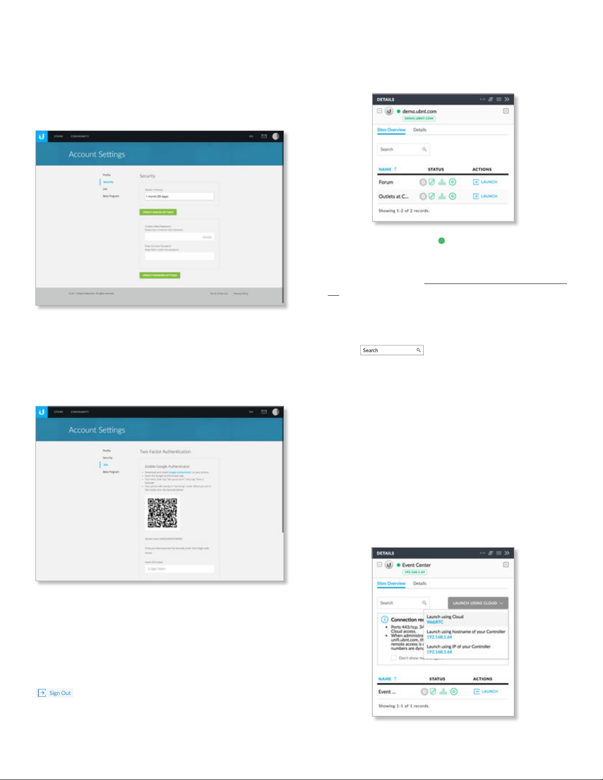
1. Launch the Chrome web browser and type
https:// followed by the appropriate Controller
Hostname/IP address as specified in “Settings >
Controller” on page 56. Press enter (PC) or return
(Mac).
2. Enter the username and password for your UBNT
account. Click Sign In.
A list of UniFi Controllers will appear.
You can apply one of the following primary filters:
• All Displays all UniFi Controllers.
• Cloud Key Only displays UniFi Cloud Keys.
• Software Installation Only displays instances of
software installations.
• Cloud Only displays UniFi Controllers with cloud access.
A secondary filter is available:
• All Displays all UniFi Controllers.
• Online Only displays online UniFi Controllers.
• Offline Only displays offline UniFi Controllers.
Discover Cloud Key Click to discover a UniFi Cloud Key
on your local network.
Search Enter the text you want to search
for. Simply begin typing; there is no need to press Enter.
You can click any of the column headers to change the
listorder.
(icon) Displays the icon corresponding to the device
running the UniFi Controller. Green indicates an active
UniFi Controller. Gray indicates an inactive UniFi Controller.
Ubiquiti Networks, Inc.
https://unifi.ubnt.com
UniFi Cloud Key
Computer
Name Displays the hostname, alias, or MAC address of
the device running the UniFi Controller. You can click the
name to get additional details at the bottom of the screen.
(Go to “Additional Details” on page 15 for more
information.)
13
Page 20
Chapter 2: UniFi Cloud UniFi Controller User Guide
Host Displays the IP address of the device running the
UniFi Controller.
Status Displays the status of the UniFi Controller:
• Online
• Offline
• Manage By Other
ONLINE
The UniFi Controller is available for access.
OFFLINE
The UniFi Controller is not available.
MANAGE BY OTHER
The UniFi Controller is
not available because it is managed by another admin.
Alerts Displays the number of alerts for the UniFi
Controller.
Sites Displays the total number of sites managed by the
UniFi Controller.
Devices Displays the total number of devices managed
by the UniFi Controller.
Clients Displays the total number of clients on the sites
managed by the UniFi Controller.
Version Displays the software version number of your
UniFi Controller.
Firmware Displays the firmware version number, if
available.
Actions Click a button to perform the desired action:
• Launch Click
LAUNCH
to access the UniFi Controller.
Proceed to “Using the UniFi Controller Software” on
page 17 for more information.
• Forget Click
FORGET
to remove the UniFi Controller
from your cloud account.
Chat At the lower left of the screen, click
to open a
window for online chat support.
The available settings are:
• Condensed view Enabled by default. The table
padding is condensed and the font size is minimized to
fit as much data on the screen as possible.
• Dark settings Enabled by default. A dark theme is used
on the Settings screens.
• Wide panel Disabled by default. If enabled, the Details
panel is displayed with maximum width.
• Show device adopt requirements Enabled by default.
• Confirm before device restart Enabled by default.
• Confirm before device reset Enabled by default.
• Find Cloud Key automatically Disabled by default.
• Find Device automatically Disabled by default.
• Show Demo Controller Enabled by default.
• Show connection requirements Enabled by default.
• Language The default is English.
Your changes are automatically saved. To cancel changes,
click Cancel. To reset to factory default settings, click
Reset to Defaults.
My Account To change your account settings and/or
password, click . The Account Settings screen
will appear:
Admin
At the top right of the screen, click the account icon
( by default or the user-specified icon) to display the
Preferences, My Account and Sign Out options:
Store Click to access the store site for UniFi
products.
Preferences To change your account preferences, click
. The Preferences screen will appear:
There are four pages available:
• Profile Access your account settings:
- First Name Enter your first name.
- Last Name Enter your last name.
- Username Enter your login username.
- Email Enter the email address of your cloud account.
- Current Password Enter your current account
password.
- Update Settings Click to apply your changes.
• Security Change the duration of your session and/or
your account password:
- Session Timeout Select the appropriate duration of
your session. You will be automatically logged out for
security purposes.
- Update Session Settings Click to apply your
changes.
14
Ubiquiti Networks, Inc.
Page 21
Chapter 2: UniFi CloudUniFi Controller User Guide
- Create a New Password Enter a new password with
at least eight characters.
- Enter Current Password Enter your current account
password.
- Update Password Settings Click to apply your
changes.
• 2FA Follow the on-screen instructions if you want
to use the Google Authenticator app for two-factor
authentication (2FA).
- Insert 2FA token Enter the 6-digit code after you
have scanned the on-screen QR code.
- Enable 2FA Click to apply the code.
Additional Details
Select a UniFi Controller to display more information on
the right side of the screen.
• (icon) A green circle icon indicates an active UniFi
Controller. Gray indicates an inactive UniFi Controller.
• (controller_name) Displays the Controller Hostname/IP
address as specified in “Settings > Controller” on page
56.
• IP Address Displays the IP address of the device
running the UniFi Controller.
Sites Overview
• Search Enter the text you want to
search for. Simply begin typing; there is no need to press
Enter.
• Launch Using Cloud If cloud access is available, then
you can use it to access the UniFi Controller. Click the
appropriate option: Launch using Cloud, Launch using
hostname of your Controller, or Launch using IP of
your Controller.
For cloud access, these are the requirements:
• Ports 443 (TCP), 3478 (UDP), and 443 (UDP) must be
open.
• If you access this Controller using unifi.ubnt.com, there
will be some outbound UDP traffic if remote access
is ongoing (via WebRTC), and the port numbers are
dynamic.
• Beta Program Follow the on-screen instructions if you
want to join the beta program.
- I agree to the Terms of Service & Beta Program
Guidelines Select to agree to the terms and
guidelines for joining the beta program.
- Join Now Click to join the beta program.
Sign Out To manually sign out of the cloud account, click
.
Ubiquiti Networks, Inc.
15
Page 22
Chapter 2: UniFi Cloud UniFi Controller User Guide
• Name Displays the name of the site. You can click the
name to get additional details on the right.
• Status Indicates the number of alerts and status of each
dashboard node.
- (Unread Alerts) Displays the number of unread
alerts.
- (WAN/LAN/WLAN) The status of each dashboard
node: UniFi Security Gateway, UniFi wired network, or
UniFi wireless network is indicated by color:
• Green Indicates an active node.
• Red Indicates that the node or some of its devices
are offline.
• Gray Gray indicates that there is no connection or
there are no devices available for thatnode.
• Actions Click a button to perform the desired action:
- Launch Click
LAUNCH
to access the UniFi Controller.
Proceed to “Using the UniFi Controller Software” on
page 17 for more information.
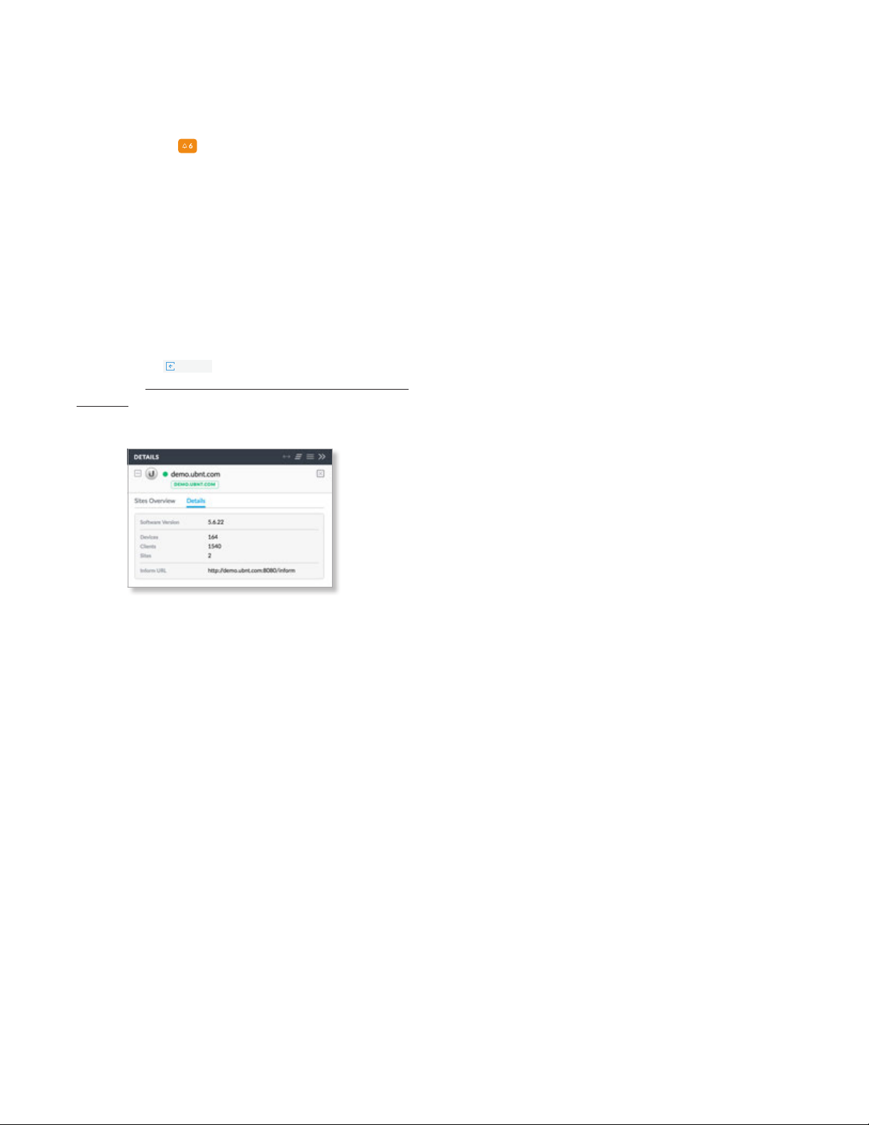
Details
• Software Version Displays the software version
number of the UniFi Controller.
• Devices Displays the total number of devices managed
by the UniFi Controller.
• Clients Displays the total number of clients on the sites
managed by the UniFi Controller.
• Sites Displays the total number of sites managed by the
UniFi Controller.
• Inform URL Displays the URL, port, and path to the
UniFi Controller. This tells UniFi APs where to look for the
UniFi Controller.
16
Ubiquiti Networks, Inc.
Page 23
UniFi Controller User Guide
Sites overview
Chapter 3: Using the UniFi Controller Software
Chapter 3: Using the UniFi
Controller Software
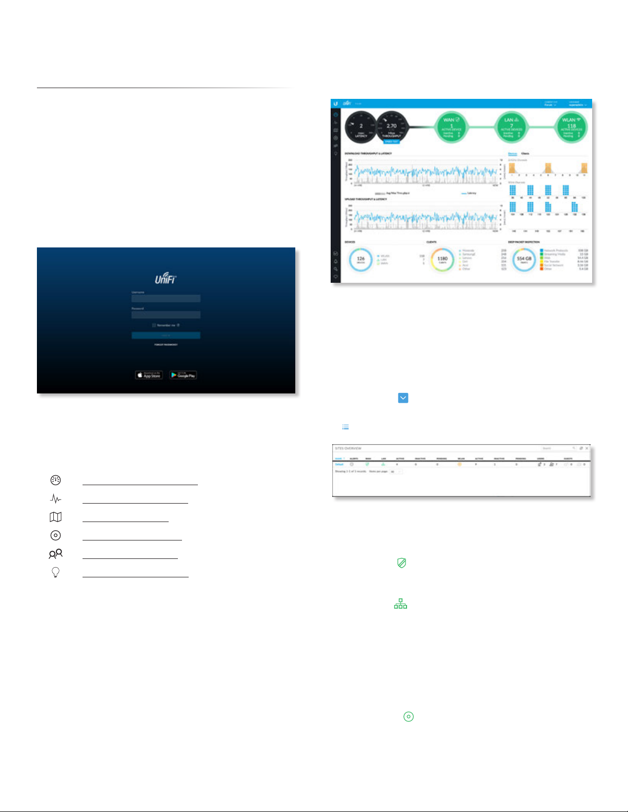
The UniFi Controller software has a browser-based
interface for easy configuration and management.
To access the interface, perform the following steps:
1. Launch the UniFi Controller application if it hasn’t
already been started.
• Mac users: Go > Applications > UniFi
• Windows users: Start > All Programs >
UbiquitiUniFi
2. The UniFi login screen will appear. Enter the username
and password in the appropriate fields and clickLogIn.
Navigation Bar
The UniFi software consists of six primary pages. This User
Guide covers each page with a chapter. For details on a
specific page, refer to the appropriate chapter.
Common Interface Options
The common interface options are accessible from all tabs
in the UniFi interface.
Current Site
The UniFi Controller can manage multiple UniFi networks,
which are called sites. Each site has its own configurations,
maps, statistics, guest portals, and site administrator
accounts. The multiple sites are logically separated, and
the initial site is named Default.
Current Site To view available sites or create a new site,
click the arrow icon.
• Sites overview To display a list of available sites, click
. The Sites Overview screen will appear.
“Dashboard” on page 63
“Statistics” on page 71
“Map” on page 81
“Devices” on page 89
“Clients” on page 99
“Insights” on page 105
Each site is displayed with the following:
- Name Displays the name of the site.
- Alerts Displays the number of pending alerts.
- WAN The icon is color-coded to display the
WAN connection status. Green indicates active; red
indicates inactive.
- LAN The icon is color-coded to display the wired
network connection status. Green indicates active; red
indicates inactive.
- Active Displays the number of active wired devices.
- Inactive Displays the number of inactive wired
devices.
- Pending Displays the number of wired devices
pending adoption.
- WLAN The icon is color-coded to display the
wireless network connection status. Green indicates
active; red indicates inactive.
Ubiquiti Networks, Inc.
17
Page 24
Chapter 3: Using the UniFi Controller Software
Add new site
- Active Displays the number of active wireless
devices.
- Inactive Displays the number of inactive wireless
devices.
- Pending Displays the number of wireless devices
pending adoption.
- Users Displays the number of wireless users and
wired users .
- Guests Displays the number of wireless guests
and wired guests .
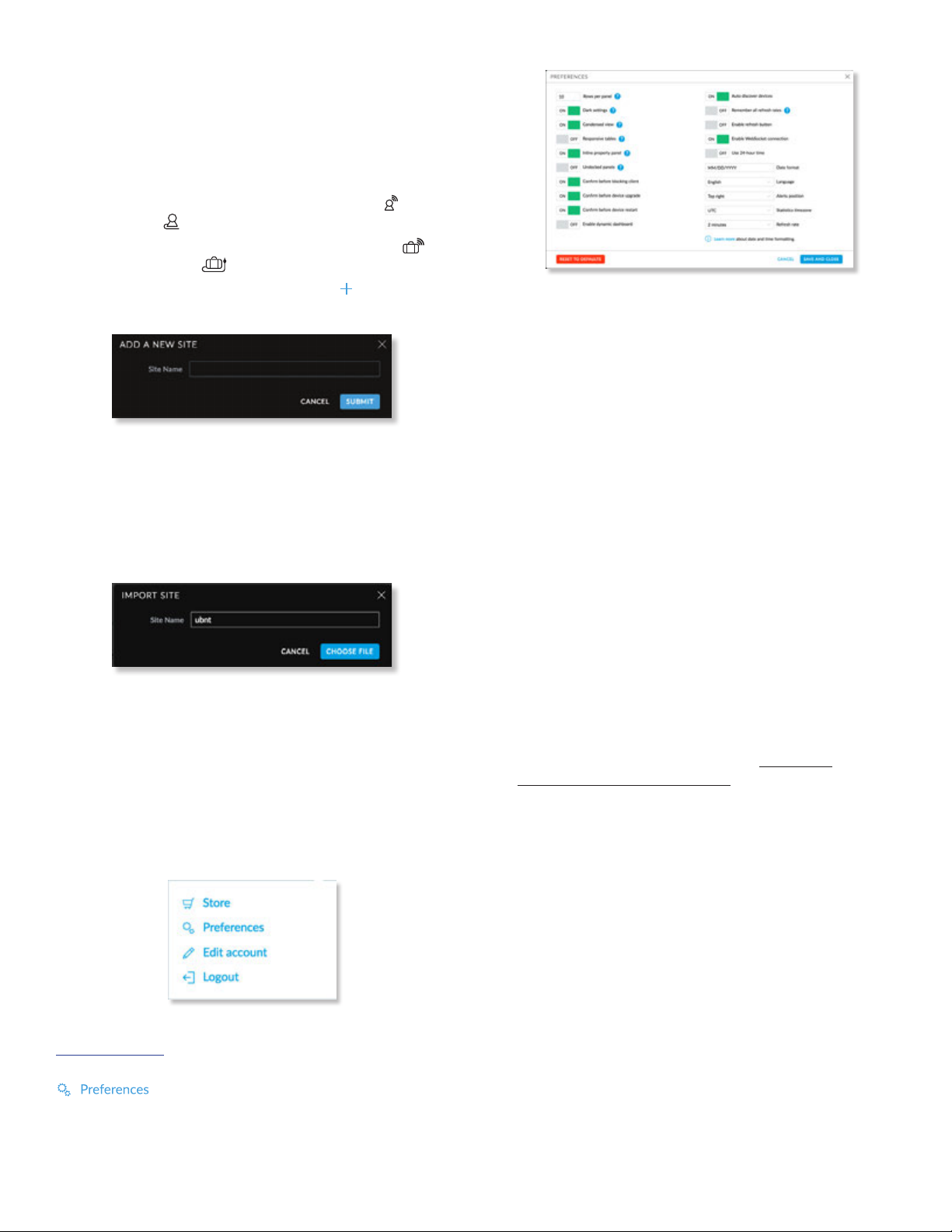
• Add new site To create a new site, click
and the Add a New Site screen will appear:
- Site Name Enter a name that describes the site. It will
be used in the Current Site drop-down menu.
- Cancel Click to discard changes.
- Submit Click to save changes.
• Import Site Click to import a new site. The Import Site
screen will appear.
- Site Name Enter a name that describes the site. It will
be used in the Current Site drop-down menu.
- Choose File Browse for the appropriate file.
- Cancel Click to discard changes.
Username
At the top right of the screen, click the Username to
display the Store, Preferences, Edit Account, and Logout
options:
Store If enabled by the admin, there is a direct link to:
store.ubnt.com
Preferences To change the UI settings, click
.
UniFi Controller User Guide
,
• Rows per panel Displays the number of rows per page
for tables in the property panels. The default is 10.
• Dark settings Enabled by default. A dark theme is used
on the Settings screens.
• Condensed view Enabled by default. The table
padding is condensed and the font size is minimized to
fit as much data on the screen as possible.
• Responsive tables Disabled by default. If enabled,
the Responsive tables option removes columns on
smaller-sized browsers to prevent excessive scrolling
when the table columns are not customized.
• Inline property panel Enabled by default. When the
property panel is inline, it compresses the main content
when it is open. When the property panel is not inline, it
opens on top of the content, as a popup.
• Undocked panels Disabled by default. Properties
appear as overlays instead of in the property panel.
• Confirm before blocking client Enabled by default.
• Confirm before device upgrade Enabled by default.
• Confirm before device restart Enabled by default.
• Enable dynamic dashboard Disabled by default. If
you enable it, then you can customize the Dashboard
display. For more information, go to “Dynamic
Dashboard (beta)” on page 69.
• Auto discover devices Enabled by default. Devices are
automatically discovered.
• Remember all refresh rates Disabled by default. Quick
refresh rates are not recommended for permanent use
or large installations.
• Enable refresh button Disabled by default. If enabled,
the refresh button is displayed.
• Enable WebSocket connection Enabled by default.
WebSocket allows cloud access.
• Use 24-hour time Disabled by default.
• Date format Enter the format you want to use. The
default is MM/DD/YYYY.
• Language Select the appropriate language.
• Alerts position Select the position you want alerts to
appear: Top left, Top center, Top right, Bottom left,
Bottom center, or Bottom right.
18
Ubiquiti Networks, Inc.
Page 25
UniFi Controller User Guide
Chapter 3: Using the UniFi Controller Software
• Statistics timezone Select the appropriate time zone
for logging the statistical data: Browser’s, Site’s, or UTC.
The default is UTC.
• Refresh rate The default is 2 minutes.
• Cancel Click to discard changes.
• Save and Close Click to save changes.
• Reset to Defaults Click to reset to factory defaults.
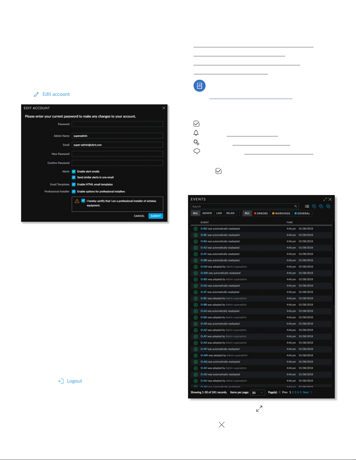
Edit Account To change the login name and/or password,
click . The Edit Account screen will appear:
depending on the device type. For more information, see
the appropriate chapter:
• “UniFi Security Gateway Details” on page 115
• “UniFi Switch Details” on page 121
• “UniFi Access Point Details” on page 131
• “Client Details” on page 147
Note: For management of the UniFi VoIP Phones,
please download the UniFi VoIP Controller:
www.ubnt.com/download/unifi
Controls and Live Chat
At the bottom left of the screen, there are four controls:
• Events
• Alerts (see “Alerts” on page 20)
• Settings
Chat with Us (see “Chat with Us” on page 62)
•
(see “Settings” on page 21)
Events
The Events tab displays a list of recent events, along
with the corresponding device icon, device name,
message, date, and time.
• Password Enter your current password.
• Admin Name Enter the admin name.
• Email Enter the email address of the admin account.
• New Password Enter the new password.
• Confirm Password Enter the new password again.
• Alerts Select this option to enable email notifications.
- Send similar alerts in one email Select this option to
group similar alerts in a single email notification.
• Email Templates Select this option to enable the use of
HTML email templates.
• Professional Installer Select this option to enable
options for professional installers. Then select I hereby
certify that I am a professional installer of wireless
equipment. (This allows you to set the antenna gain for
the UAP-AC-M device, which has a detachable antenna.)
• Submit Click to apply changes.
• Cancel Click to discard changes.
Logout To manually sign out of the UniFi Configuration
Interface, click .
Properties
The Properties panel is hidden by default. To display it,
select a device.
Information about each selected device appears as
a popup within this panel. The information varies
Maximize/Minimize Click to maximize the screen size.
Click again to minimize the screen size.
Close Click to close the screen.
Ubiquiti Networks, Inc.
19
Page 26

Chapter 3: Using the UniFi Controller Software
Search You can enter text that you want
to search for. Simply begin typing; there is no need to
press Enter.
You can apply one of the following filters to filter recent
events based on the time period you specify:
• (All) Display all of the recent events.
• (1 day) Filter recent events for a one-day duration.
• (7 days) Filter recent events to display a week’s
duration.
• (31 days) Filter recent events to display a month’s
duration.
You can apply one of the following filters:
• All Display all of the recent events.
• Admin Only display recent events for the administrator.
• LAN Only display recent events for the wired network.
• WLAN Only display recent events for the wireless
networks.
You can apply one of the following filters:
• All Display all of the recent events.
• Error Only display error-level events.
• Warnings Only display warning-level events.
• General Only display general-level events.
Icons
The messages use the following icons (not all are shown
here):
Scheduled for upgrade
UniFi Security Gateway
UniFi Switch
UniFi Access Point
Clicking an Event Device Link
The messages have clickable links for client and UniFi
devices:
• “UniFi Security Gateway Details” on page 115
• “UniFi Switch Details” on page 121
• “UniFi Access Point Details” on page 131
• “Client Details” on page 147
Alerts
When there is a new alert, an orange icon displaying the
number of new alerts appears.
The Alerts tab displays a list of important events,
along with the corresponding device icon, device name,
message, date, andtime.
UniFi Controller User Guide
Maximize/Minimize Click to maximize the screen size.
Click again to minimize the screen size.
Close Click to close the screen.
Search You can enter text that you want
to search for. Simply begin typing; there is no need to
press Enter.
You can apply one of the following filters to filter recent
alerts based on the time period you specify:
• (All) Display all of the recent alerts.
• (1 day) Filter recent alerts for a one-day duration.
• (7 days) Filter recent alerts to display a week’s
duration.
• (31 days) Filter recent alerts to display a month’s
duration.
Show archived alerts Select this option to display all of
the archived alert messages.
You can apply one of the following filters:
• All Display all of the recent events.
• Error Only display error-level events.
• Warnings Only display warning-level events.
Archive All Click Archive All to archive all of the alert
messages.
Archive Click to archive the selected alert message.
Icons
The messages use the following icons (not all are shown
here):
UniFi Security Gateway
UniFi Switch
UniFi Access Point
Clicking an Alert Device Link
The messages have clickable links for client and UniFi
devices:
• “UniFi Security Gateway Details” on page 115
• “UniFi Switch Details” on page 121
• “UniFi Access Point Details” on page 131
• “Client Details” on page 147
20
Ubiquiti Networks, Inc.
Page 27
UniFi Controller User Guide
Chapter 3: Using the UniFi Controller Software
Settings
The Settings tab displays a list of available sub-tabs:
• “Settings > Site” on page 21
• “Settings > Wireless Networks” on page 22
• “Settings > Networks” on page 27
• “Settings > Routing & Firewall” on page 31
• “Settings > Guest Control” on page 37
• “Settings > Profiles” on page 45
• “Settings > Services” on page 48
• “Settings > Admins” on page 53
• “Settings > User Groups” on page 54
• “Settings > DPI” on page 55
• “Settings > Controller” on page 56
• “Settings > Notifications” on page 57
• “Settings > Cloud Access” on page 58
• “Settings > Elite” on page 59
• “Settings > Maintenance” on page 59
• “Settings > Auto Backup” on page 62
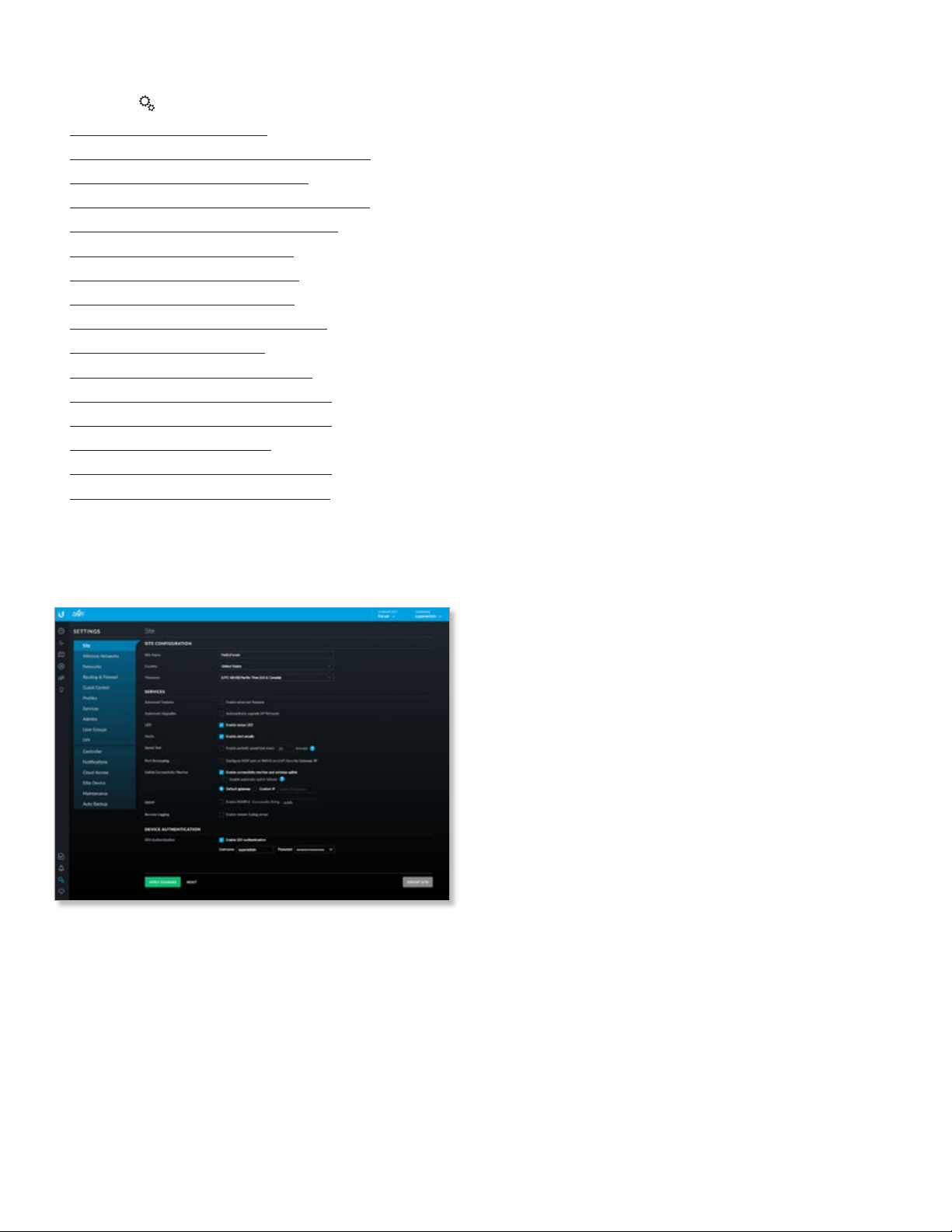
Settings > Site
Configure the site-specific settings. To switch sites, select a
different site from the Current Site drop-down menu at the
top of any screen.
Site Configuration
Site Name Change the name of the site.
Country Select the appropriate country.
Time Zone Select the appropriate time zone.
Services
Advanced Features When enabled, airtime fairness,
bandsteering, minimum RSSI, and load balancing features
become available.
Automatic Upgrade When enabled, the UniFi Controller
will automatically upgrade your APs’ firmware when an
update is available.
LED When enabled, the status LEDs on the UniFi devices
will light up. When disabled, the LEDs will turn off.
Alerts Select this option to enable alert emails, which will
be sent to the email addresses of the administrators.
Speed Test When enabled, you can run a periodic speed
test. Enter the interval in minutes.
Port Remapping When enabled, the VOIP port on the
UniFi Security Gateway, model USG, will be remapped as a
WAN2 port.
Uplink Connectivity Monitor It monitors the uplinks of
the managed APs, either wired or wireless, by checking to
see if the gateway/custom IP can be reached.
• Enable connectivity monitor and wireless uplink The
monitor and wireless uplink capability are enabled by
default.
- Enable automatic uplink failover Enable this option
to have the UniFi Controller automatically select a new
wireless uplink if the original uplink fails. This allows
the UniFi APs to switch to alternative uplinks/mesh
configurations if a node fails.
• Default Gateway Enabled by default. All managed
APs will use the gateway of the AP that is providing IP
information, either by DHCP or Static designation.
• Custom IP Click to specify an IP address.
- Uplink IP Address All managed APs will use the IP
address you enter.
SNMP Select this option to activate the SNMP
(Simple Network Monitor Protocol) agent. SNMP
is an application layer protocol that facilitates the
exchange of management information between
network devices. Network administrators use SNMP
to monitor network-attached devices for issues that
warrantattention.
• Community String Specify the SNMP community
string. It is required to authenticate access to MIB
(Management Information Base) objects and functions
as an embedded password. The device supports a
read-only community string; authorized management
stations have read access to all the objects in the MIB
except the community strings, but do not have write
access. The device supports SNMP v1. The default
ispublic.
Remote Logging Enable to define a remote syslog server.
• Enable debug logging Select this option to create
debug logs.
• Remote IP or Hostname Enter the IP address or
hostname of the syslog server.
• Port Enter the port number of the syslog server. The
default is 514.
Device Authentication
SSH Authentication This option protects SSH access to
the UniFi devices. All devices in the same site share the
same SSH username and password. You can also make
changes:
Ubiquiti Networks, Inc.
21
Page 28

Chapter 3: Using the UniFi Controller Software
UniFi Controller User Guide
• Username Enter the new username.
• Password Enter the new password.
Apply Changes Click to save changes.
Reset Click to cancel changes.
Export Site Click to export the site to another controller
of the same or higher version number. Then follow the
on-screen instructions.
• Download Backup File Click to download a backup
configuration file.
• Cancel Click to cancel the export.
Settings > Wireless Networks
Configure the wireless networks for each site. You can
have up to four wireless network names or SSIDs per
WLANgroup.
• Mobility To enable seamless roaming (Zero Handoff ),
select the checkbox.
Note: Not all UniFi APs support Zero Handoff
Roaming.
When you enable this option, multiple Access Points
(APs) act as an AP cluster, appearing as a single AP. The
wireless client detects only one AP, so it seamlessly
roams from AP to AP – there is no need to re-negotiate.
The APs determine which AP has the best connection
and should serve the client. They use multicasting to
communicate so they must be wired in the same Layer 2
domain.
Zero Handoff Roaming does not support wireless
uplinks and can only be used on a secured network. It
is also not meant for all scenarios. For example, if there
is too much load or interference, then Zero Handoff
Roaming may not be appropriate for your scenario.
WLAN Group The Default WLAN group is automatically
created.
Add a New WLAN Group To add a new WLAN group,
click the button. Go to the Add or Edit a WLAN Group
section.
Add or Edit a WLAN Group
Configure the following options:
- Radio Select the appropriate radio, 2G or 5G.
- Channel Select the channel that all of the APs will use
for Zero Handoff Roaming.
• Legacy Support (Not available if you enabled the
Mobility option.) By default, legacy devices, such as
802.11b devices, are excluded. Select this option if you
want to support legacy devices.
Advanced Options Click to display more options.
• Name Enter or edit a descriptive name for the WLAN
group.
22
Ubiquiti Networks, Inc.
Page 29

UniFi Controller User Guide
Chapter 3: Using the UniFi Controller Software
• PMF Enabling PMF (Protected Management
Frames) may cause a drop in performance. Select the
appropriate option:
- Disabled The UniFi APs will not use PMF for any
stations.
- Optional The UniFi APs will use PMF for all PMFcapable stations while allowing non-PMF-capable
stations to join the wireless network.
- Required The UniFi APs will use PMF for all stations.
Stations that are not capable of PMF will not be
allowed to join the wireless network.
Save Click to apply changes.
Cancel Click to discard changes.
For each WLAN group, you have the following:
• Remove a WLAN Group To remove a WLAN group
(except for the Default, which cannot be removed),
select it from the drop-down menu, and then click the
delete button.
• Options To make changes, select the WLAN group from
the drop-down menu, and then click the edit button.
Go to “Add or Edit a WLAN Group” on page 22.
Wireless Networks
Name Displays the wireless network name or SSID.
Security Displays the type of security being used on your
wireless network.
Guest Network Indicates whether or not the network is a
guest network.
VLAN Indicates its VLAN ID.
Actions Click a button to perform the desired action:
• Edit Click
network settings. Go to the Create or Edit a Wireless
Network section.
• Delete Click
Create Wireless Network Click
a wireless network. Go to the Create or Edit a Wireless
Network
section.
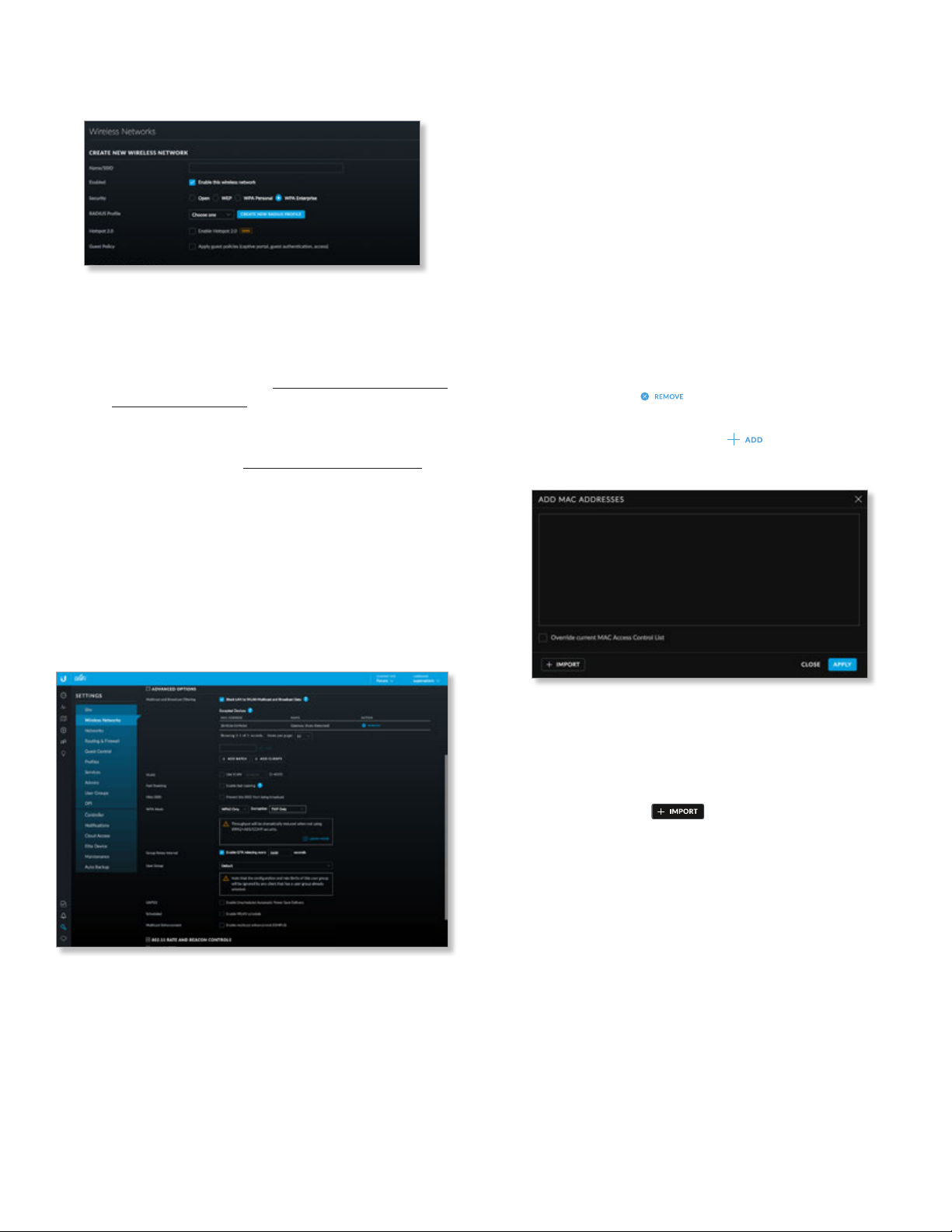
Create or Edit a Wireless Network
EDIT
to make changes to the wireless
to remove the wireless network.
to add
• Name/SSID Enter or edit the wireless network name
orSSID.
• Enabled Select this option to make the network active.
• Security Select the type of security to use on your
wireless network.
- Open This option is typically only used on the guest
network. When enabled, wireless network access is
open to anyone without requiring a password.
- WEP WEP (Wired Equivalent Privacy) is the oldest
and least secure security algorithm. WPA™ security
methods should be used when possible.
• WEP Key Enter a WEP encryption key in
hexadecimal format. You can enter a 64-bit or
128-bit key:
Type Hex
64-bit 10 Hexadecimal Characters
(0-9, A-F, or a-f )
Example: 00112233AA
Note: You can use 5 printable characters, which
will be translated to the corresponding HEX code.
128-bit 26 Hexadecimal Characters
(0-9, A-F, or a-f )
Example: 00112233445566778899AABBCC
Note: You can use 13 printable characters, which
will be translated to the corresponding HEX code.
• Key Index Specify which Index of the WEP Key
to use. Four different WEP keys can be configured
at the same time, but only one is used. Select the
effective key: 1, 2, 3, or 4.
- WPA-Personal WPA or Wi-Fi Protected Access was
developed as an encryption method stronger than
WEP. WPA-Personal requires a passphrase to connect
to the wireless network.
Ubiquiti Networks, Inc.
• Security Key Enter the passphrase that users will
use to connect to the wireless network.
23
Page 30
Chapter 3: Using the UniFi Controller Software
UniFi Controller User Guide
- WPA-Enterprise WPA Enterprise uses a RADIUS
server to authenticate users on the wireless network.
• RADIUS Profile Specify a RADIUS profile:
• Select a RADIUS profile from the drop-down list,
or
• Click Create New RADIUS Profile to create a new
RADIUS profile. Refer to “Create or Edit a RADIUS
Profile” on page 45 for detailed information.
• Hotspot 2.0 Select this option to enable Hotspot
2.0. Then select a Hotspot profile from the
drop-down list. Go to “Hotspot 2.0” on page 49
for more information.
• Guest Policy Select this option to enable guest access
policies on this wireless network. By default, guest
policies will drop broadcast traffic from wireless stations
and also block LAN => WAN broadcast and multicast
data from all except the default gateway. See Advanced
Options for custom whitelisting.
Advanced Options
Click to display options for advanced users.
Multicast/broadcast data is sent out at the lowest
modulation rate, so we recommend that you block this
traffic unless it is absolutely essential. Disable this option
if proper multicast/broadcast controls are already
implemented on the LAN infrastructure.
- Excepted Devices You can specify devices that need
to send multicast/broadcast data to Wi-Fi stations. In
most cases, only the default gateway needs to send
multicast data to Wi-Fi stations and is automatically
added by the UniFi Controller. You can add any other
devices, such as Bonjour printers or Chromecast
devices.
• MAC Address Displays the MAC address of the
device.
• Name Displays the name or hostname of the
device.
• Action Click to remove this device.
• (MAC_address) To add an excepted device, enter
the MAC address and click .
• Add Batch Click to add a group of devices.
• Multicast and Broadcast Filtering Disabled by
default. We recommend to enable it if there are more
than 100 wireless clients on a single Layer-2 network.
When Multicast and Broadcast Filtering is enabled,
devices such as Chromecasts and Apple TVs will not be
discovered unless the USG MDNS service is enabled.
• (MAC_addresses) Enter the MAC addresses in
the field provided.
• Override current MAC Access Control
List Select this option to override this list.
Disabled by default.
• Import Click to import a list of MAC
addresses.
• Apply Click to save changes.
• Close Click to exit the screen without saving any
changes.
24
Ubiquiti Networks, Inc.
Page 31
UniFi Controller User Guide
Chapter 3: Using the UniFi Controller Software
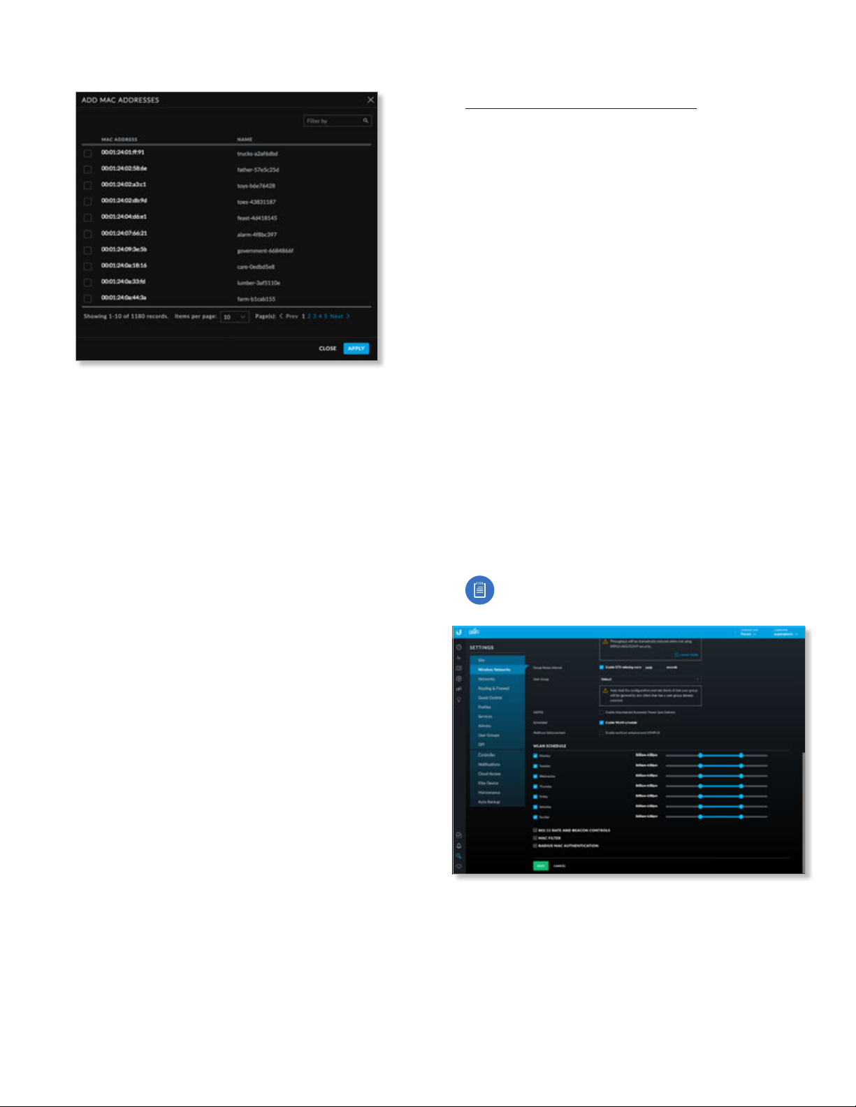
• Add Clients Click to add a group of wireless clients.
• Filter by Enter keywords to search for specific
devices.
• MAC Address Displays the MAC address of the
client device.
• Name Displays the name or hostname of the
client device.
• Apply Select the client devices and then click to
save changes.
• Close Click to exit the screen without saving any
changes.
• VLAN To use a VLAN, select Use VLAN ID and enter the
VLAN ID number.
• Fast Roaming Fast Roaming allows certain devices with
802.11r capabilities to potentially roam more quickly.
However, older devices may experience connectivity
issues due to their lack of 802.11r client-side support or
compatibility. Select this option with caution.
• Hide SSID Select this option if you don’t want the
wireless network name or SSID to be broadcast.
• WPA Mode (Available if WPA security is enabled.) Select
the appropriate WPA method: Both, WPA1 Only, or
WPA2 Only (default).
- Encryption (Available if WPA security is enabled.)
Select the appropriate encryption method: Auto,
TKIPOnly, or AES/CCMPOnly (default).
• Group Rekey Interval (Available if WPA security is
enabled.) Select this option to rekey the GTK (Group
Temporal Key) after an interval specified in seconds. The
default is 3600 seconds.
• User Group Assign wireless users to a specific user
group. For more information about user groups, see
“Settings > User Groups” on page 54.
• UAPSD Disabled by default. Select UAPSD
(Unscheduled Automatic Power Save Delivery) to enable
the power save mode of Wi-Fi devices.
• Scheduled Select Enable WLAN Schedule to restrict
wireless access to the schedule you set.
- Monday-Sunday Select the days you want to
schedule.
- (hours) Use the slider bars to adjust the start and end
times of the day’s wireless access.
• Multicast Enhancement Disabled by default. Enabling
Multicast Enhancement is useful for applications such as
IPTV installations.
If clients do not send IGMP (Internet Group
Management Protocol) messages, then they are
not registered as receivers of your multicast traffic.
Using IGMP snooping, Multicast Enhancement isolates
multicast traffic from unregistered clients and allows
the device to send multicast traffic to registered clients
using higher data rates. This may lessen the risk of
traffic overload and increase the reliability of multicast
traffic since packets are transmitted again if the first
transmission fails.
If clients do not send IGMP messages but should receive
multicast traffic, then you may need to keep Multicast
Enhancement disabled.
Note: IGMPv3 is supported by the UniFi APs.
Ubiquiti Networks, Inc.
25
Page 32
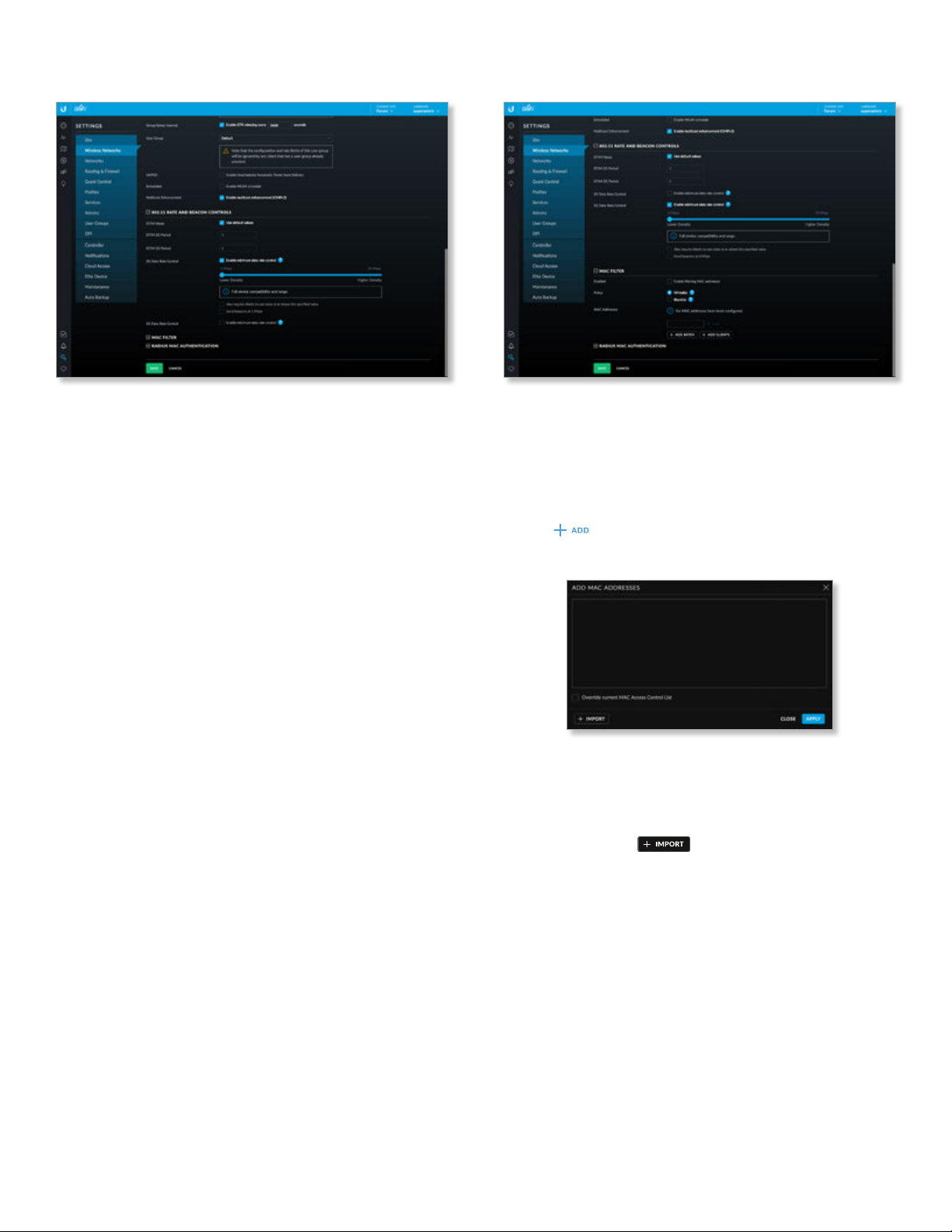
Chapter 3: Using the UniFi Controller Software
UniFi Controller User Guide
802.11 Rate and Beacon Controls
• DTIM Mode Select this option to use the default DTIM
(Delivery Traffic Indication Message) values. Increasing
the DTIM values allows devices to conserve power, at a
slight latency penalty. Deselect it to configure the values
below.
• DTIM 2G Period Enter the number of beacons between
the 2.4 GHz DTIM beacons. The default is 1.
• DTIM 5G Period Enter the number of beacons between
the 5 GHz DTIM beacons. The default is 1.
• 2G Data Rate Control Select this option to determine
what bit rates your 2.4 GHz network will allow. Disabling
lower bit rates can improve performance for higherdensity networks but will make some older devices
incompatible with your network and limit the range of
your wireless network.
- Also require clients to use rates at or above the
specified value Select this option to set minimum
rates for clients.
- Send beacons at 1 Mbps Select this option to set the
beacon speed at 1 Mbps.
• 5G Data Rate Control Select this option to determine
what bit rates your network will allow. Disabling
lower bit rates can improve performance for higherdensity networks but will make some older devices
incompatible with your network and limit the range of
your wireless network.
- Also require clients to use rates at or above the
specified value Select this option to set minimum
rates for clients.
- Send beacons at 6 Mbps Select this option to set the
beacon speed at 6 Mbps.
MAC Filter
• Enabled Select this option to filter MAC addresses.
• Policy Select Whitelist to allow connections from the
following MAC addresses; all others will be blocked.
Select Blacklist to block connections from the following
MAC addresses; all others will be allowed.
• MAC Addresses To add a MAC address, enter it and
click .
- Add Batch Click to add a group of devices.
• (MAC_addresses) Enter the MAC addresses in the
field provided.
• Override current MAC Access Control List Select
this option to override this list. Disabled by default.
• Import Click to import a list of MAC
addresses.
• Apply Click to save changes.
• Close Click to cancel changes.
26
Ubiquiti Networks, Inc.
Page 33
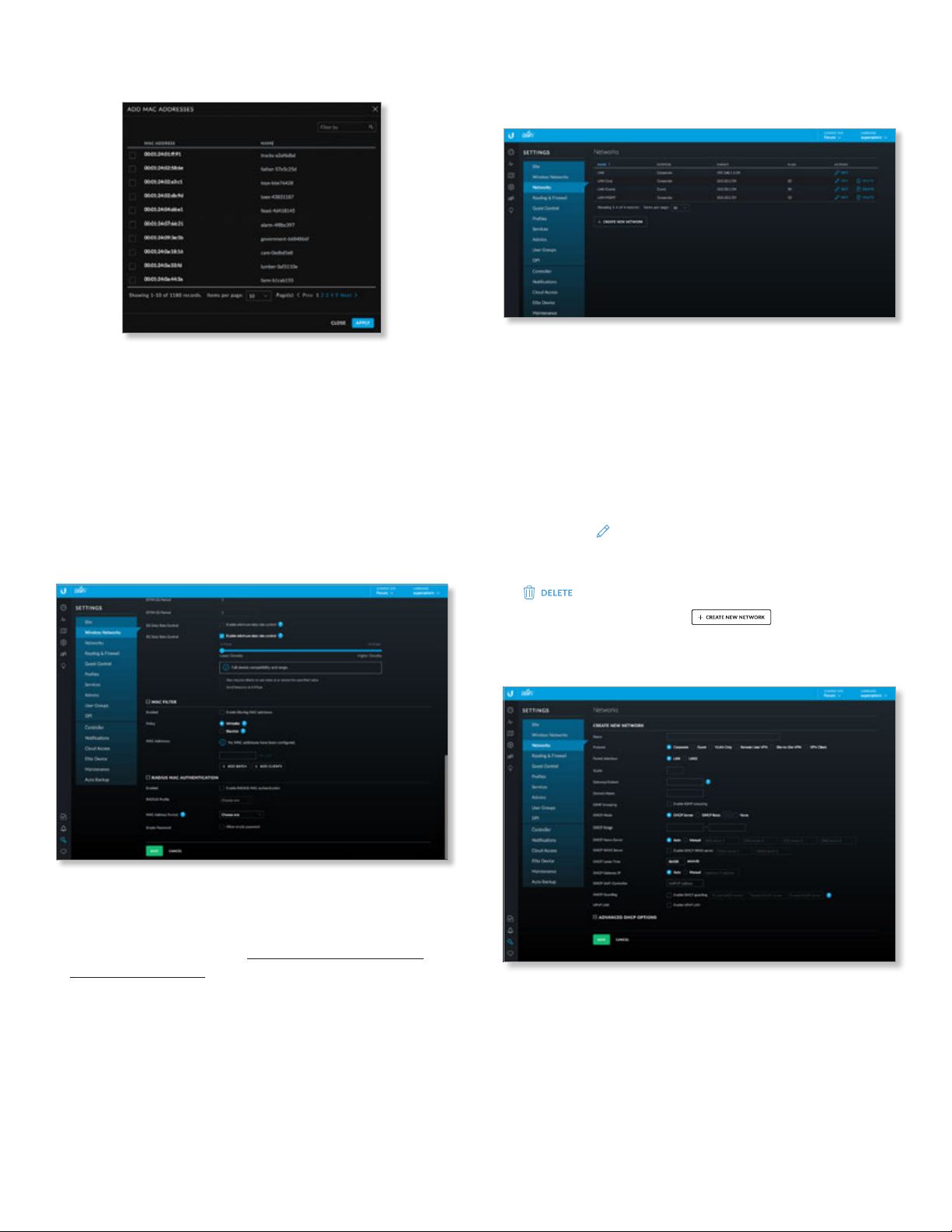
UniFi Controller User Guide
Chapter 3: Using the UniFi Controller Software
- Add Clients Click to add a group of wireless clients.
• Filter by Enter keywords to search for specific
devices.
• MAC Address Displays the MAC address of the
client device.
• Name Displays the name or hostname of the client
device.
• Apply Select the client devices and then click to
save changes.
• Close Click to cancel changes.
RADIUS MAC Authentication
Settings > Networks
Configure the networks for each site.
Networks
Name Displays the network name.
Purpose Displays the purpose of this network: Corporate,
Guest, VLAN Only, Remote User VPN, Site‑to‑Site VPN, or
VPNClient.
Subnet Displays the IP address and prefix size.
VLAN Displays the VLAN ID, if applicable.
Actions Click a button to perform the desired action:
• Edit Click
settings. Go to the Create or Edit a Network section.
• Delete (Not available for the default network.) Click
Create New Network Click
Go to the Create or Edit a Network section.
Create or Edit a Network
EDIT
to make changes to the network
to remove the network.
to add a network.
• Enabled Select this option to enable RADIUS MAC
authentication.
• RADIUS Profile Select the appropriate RADIUS profile
or create a new one; go to “Create or Edit a RADIUS
Profile” on page 45 for more information.
• MAC Address Format Select the format used to
convert a client’s MAC address to the RADIUS username.
• Empty Password Select this option to allow a blank
password.
• Save Click to apply changes.
• Cancel Click to discard changes.
Ubiquiti Networks, Inc.
• Name Enter or edit the network name.
• Purpose Select the most appropriate description:
- Corporate Corporate networks are appropriate
for networks containing trusted systems. Corporate
networks have no restrictions between them, or from
them to the internet, by default.
27
Page 34
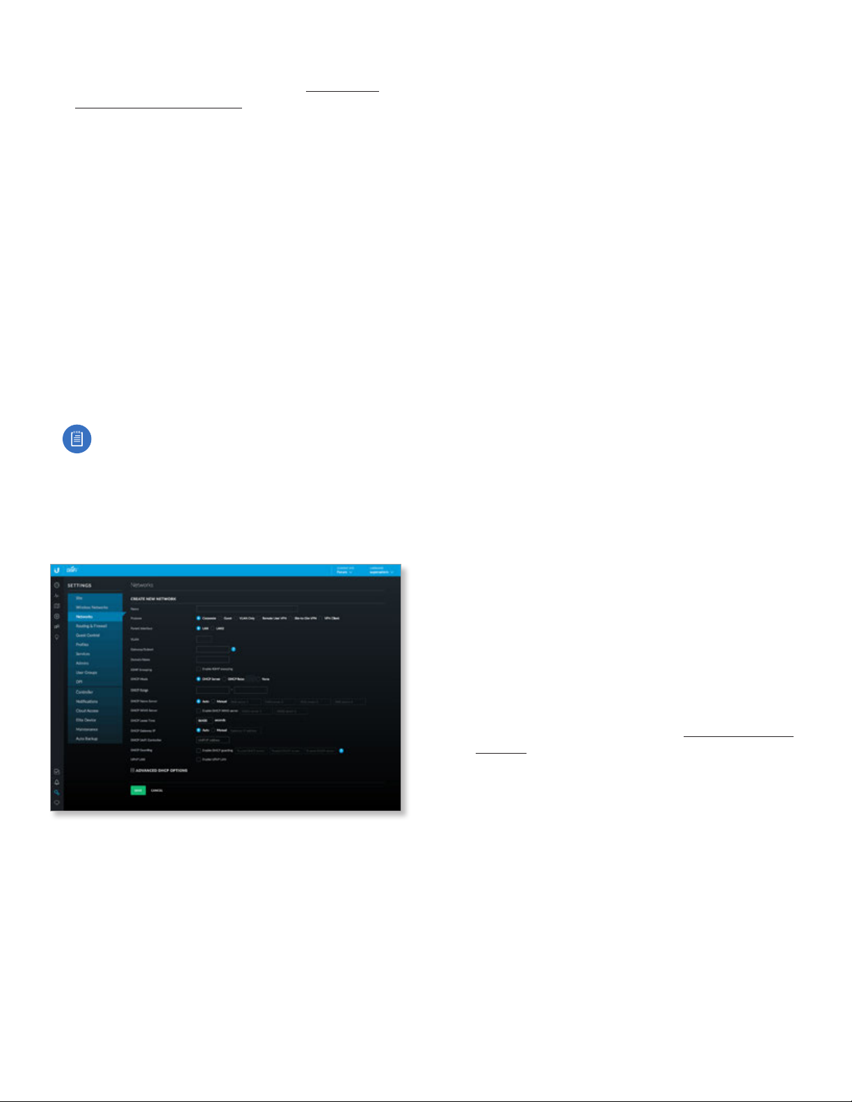
Chapter 3: Using the UniFi Controller Software
UniFi Controller User Guide
- Guest Guest networks are often used in combination
with the Guest Control feature (refer to “Settings >
Guest Control” on page 37) for limiting access. The
default Guest Control restrictions block authenticated
guests from reaching any private IP subnet (RFC 1918).
- VLAN Only Deploys the configured VLAN ID and
associated configuration to the UniFi Switch(es).
- Remote User VPN Allows configuration of a UniFi
Security Gateway as a remote access PPTP or L2TP
VPN server to connect mobile VPN clients.
- Site-to-Site VPN Site-to-site VPNs connect different
networks with an always-on connection and routing
between. Auto, IPsec, and OpenVPN options are
available.
- VPN Client Configures a VPN client on the UniFi
Security Gateway to connect to a remote PPTP VPN
server, acting like a mobile client would. Traffic
leaving VPN client interfaces is source NATed to the IP
assigned to the VPN client, so return routing from the
server side isn’t needed.
Note: The Corporate, Guest, Remote User VPN,
Site‑to‑Site VPN, and VPNClient settings apply to
the UniFi Security Gateway only. The VLAN Only
setting applies only to UniFi Switches.
After making your selection, follow the instructions for
your selection:
Corporate or Guest Network
• Parent Interface Select the physical interface of the
USG that this network will be associated with: LAN1 or
LAN2.
• VLAN (Not available for the default Corporate network,
LAN.) Enter the VLAN ID.
• Gateway/Subnet Enter the IP address and subnet
mask.
• Domain Name Enter the domain name.
• IGMP Snooping Select this option to monitor IGMP
(Internet Group Management Protocol) traffic and
thereby manage multicast traffic.
• DHCP Mode Select the appropriate option: DHCP
Server, DHCP Relay, or None.
- DHCP Server Enabled by default. The local DHCP
server assigns IP addresses to DHCP clients on the
network.
• DHCP Range Enter the starting and ending IP
addresses of the range in the fields provided.
• DHCP Name Server Configure the name or DNS
(Domain Name System) server setting:
• Auto Enabled by default. When this option is
selected, all clients on the network are assigned
the UniFi Security Gateway’s IP address as their
DNS server. The clients will then use the UniFi
Security Gateway’s caching DNS resolver as their
DNS server.
• Manual Select this option to specify name
servers. Then enter the IP address of a server in
each DNS server field.
• DHCP WINS Server Select this option to designate
WINS (Windows Internet Naming Service) server(s).
Then enter the IP address of a server in each WINS
server field.
• DHCP Lease Time Enter the DHCP lease time in
seconds. The IP addresses assigned by the DHCP
server are valid only for the duration specified by
the lease time. Increasing the lease time will extend
the time clients retain their IP address in absence
of the DHCP server. However, any network changes
will take just over half the lease length to apply to
all clients. In networks with high rates of device
churn, much shorter lease lengths should be used
to prevent exhausting the DHCP IP address pool.
• DHCP UniFi Controller Enter the IP address of the
UniFi Controller.
- DHCP Relay Select this option to enable DHCP relay,
which forwards DHCP packets to a DHCP server when
DHCP clients are not on the same local network or
subnet as their DHCP server. Go to “DHCP Relay” on
page 51 for configuration instructions.
- None Select this option to disable DHCP.
• DHCP Guarding Disabled by default. Select this option
to detect and block unauthorized DHCP servers. DHCP
guarding configures UniFi Switches to restrict DHCP
servers on this network to the IP address(es) specified
here. All other IP addresses attempting to serve DHCP
will have the DHCP responses blocked, and the UniFi
Controller will generate an alert.
- Trusted DHCP Server Enter the IP address of a
trusted DHCP server in each field.
• UPnP LAN Disabled by default. Select this option
to allow UPnP (Universal Plug and Play) on the local
network.
• Save Click to apply changes.
• Cancel Click to discard changes.
28
Ubiquiti Networks, Inc.
Page 35
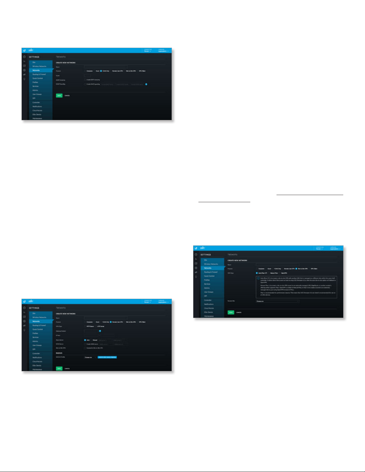
UniFi Controller User Guide
Chapter 3: Using the UniFi Controller Software
VLAN Only
The UniFi Switch is required for this option.
• VLAN Enter the ID number of the VLAN. Devices
belonging to the same VLAN communicate as if
they were attached to the same wire. Every VLAN ID
represents a different VLAN. The VLAN ID range is 2 to
4009.
• IGMP Snooping Select this option to monitor IGMP
(Internet Group Management Protocol) traffic and
thereby manage multicast traffic.
• DHCP Guarding Disabled by default. Select this option
to detect and block unauthorized DHCP servers. DHCP
guarding configures UniFi Switches to restrict DHCP
servers on this network to the IP address(es) specified
here. All other IP addresses attempting to serve DHCP
will have the DHCP responses blocked, and the UniFi
Controller will generate an alert.
- Trusted DHCP Server Enter the IP address of a
trusted DHCP server in each field.
• Save Click to apply changes.
• Cancel Click to discard changes.
Remote User VPN
The UniFi Security Gateway is required for this option.
• IP Pool The starting and ending IP addresses of the
pool automatically appear after you complete the
Gateway/Subnet field. These are the IP addresses that
will be assigned to connected VPN clients.
• Name Server Configure the name or DNS (Domain
Name System) server setting.
- Auto Enabled by default. Name servers are
automatically assigned by the DHCP server.
- Manual Select this option to specify name servers.
Then enter the IP address of a server in each DNS
server field.
• WINS Server Select this option to designate WINS
(Windows Internet Naming Service) server(s). Then enter
the IP address of a server in each WINS server field.
• Site-to-Site VPN Enabled by default. The remote user
can access the site’s resources as well as the resources of
any other VPNs connected to the site. If you disable this
option, then the remote user can only access the site’s
resources.
• RADIUS Profile Select a RADIUS profile from the dropdown list, or click Create New RADIUS Profile to create
a new RADIUS profile. Refer to “Create or Edit a RADIUS
Profile” on page 45 for information.
• Save Click to apply changes.
• Cancel Click to discard changes.
Site-to-Site VPN
The UniFi Security Gateway is required for this option.
• VPN Type To connect mobile VPN clients, configure the
UniFi Security Gateway as a remote access VPN server.
Select the appropriate server type, PPTP Server or L2TP
Server.
• Gateway/Subnet Enter the IP address and subnet
mask.
Ubiquiti Networks, Inc.
• VPN Type Select the type of VPN being configured:
Auto IPsec VTI, Manual IPsec, or OpenVPN.
- Auto IPsec VTI Auto IPsec VTI is the default. This
option lets you connect two sites on the same
controller by simply picking the other site. The other
end of the VPN tunnel uses a UniFi Security Gateway
managed on a different site within the same UniFi
Controller. If either side of the tunnel is using USG
firmware 4.2.x, then the Auto IPsec VTI option will fall
back to OpenVPN.
No further configuration is necessary; UniFi
automatically creates a secure IPsec VPN and
configures routing between the sites. Also, the VPN
connection is bidirectional: creating an auto VPN from
site A to site B also provides connectivity from site B to
site A (nothing is configured on site B).
29
Page 36
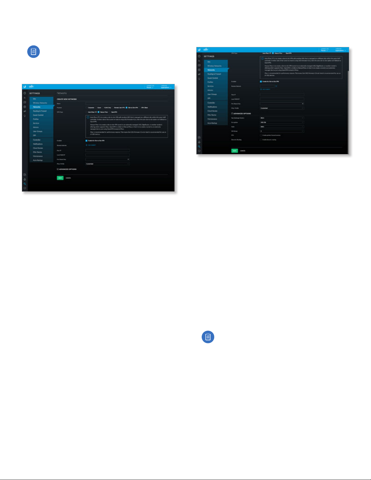
Chapter 3: Using the UniFi Controller Software
UniFi Controller User Guide
• Remote Site Select the appropriate site from the
drop-down list.
Note: You must have admin privileges for the local
and remote sites to view and select sites.
- IPsec VPN Select this option to create a VPN that uses
IPsec (IP security protocol).
• Enabled Select this option to create an IPsec VPN
tunnel between two peer routers over the internet,
from a local device to an externally managed device,
such as an externally managed UniFi Security
Gateway, EdgeRouter™, or third-party device that
supports IPsec. (The UniFi Security Gateway is the
local peer router.)
• Remote Subnets Click Add Subnet to add an
address for a remote network.
• Peer IP Enter the internet IP address of the remote
peer router.
• Local WAN IP Enter the internet IP address of the
local UniFi Security Gateway.
• Pre-Shared Key Enter the pre-shared secret key.
Both peer routers must use the same pre-shared
secret key for authentication.
• IPsec Profile Select the appropriate option:
• Customized Select this option to customize your
settings.
• Azure dynamic routing Select this option if you
are using Microsoft Azure with dynamic routing
for a route-based VPN.
• Azure static routing Select this option if you are
using Microsoft Azure with static routing for a
policy-based VPN.
• Advanced Options Click to access the advanced
configuration.
• Key Exchange Version Both peer routers must
use the same Internet Key Exchange (IKE) version.
Select the appropriate version: IKEv1 or IKEv2.
• Encryption Both peer routers must use the
same encryption method. Select the appropriate
encryption method: AES-128, AES-256, or 3DES.
• Hash Both peer routers must use the same hash
algorithm. Select the appropriate hash algorithm:
SHA1 or MD5.
• DH Group The DH (Diffie-Hellman) group
specifies the strength of the DH encryption key
for the key exchange. Both peer routers must use
the same DH group. Select the appropriate DH
group: 2, 5, 14, 15, 16, 19, 20, 21, 25, or 26. The
default is 14.
• PFS Select this option to enable PFS (Perfect
Forward Secrecy), which protects your past
sessions from decryption should your key be
compromised in the future.
• Dynamic Routing Select this option to use VTI-
based IPsec (otherwise tunnel mode will be used).
Note: If you selected Azure dynamic routing or
Azure static routing, then the defaults of the
Advanced Options will also change accordingly.
30
Ubiquiti Networks, Inc.
Page 37
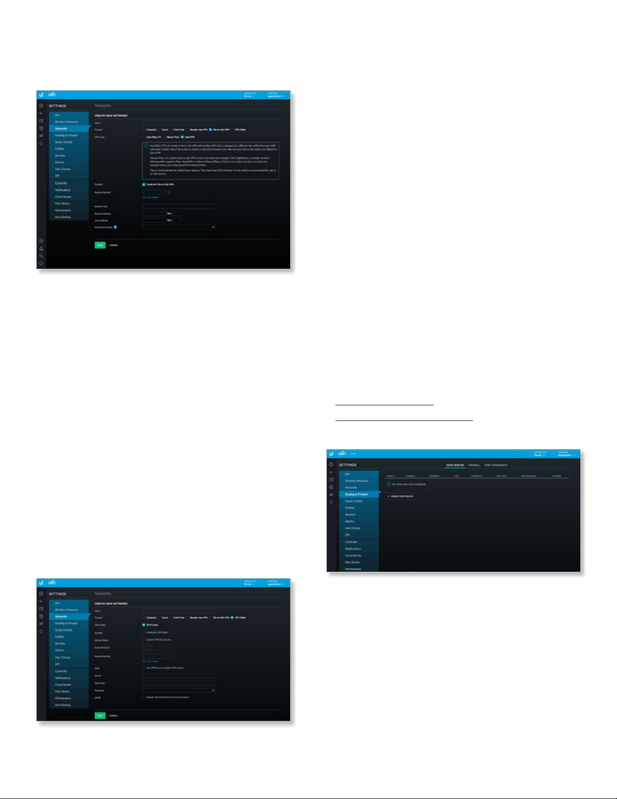
UniFi Controller User Guide
Chapter 3: Using the UniFi Controller Software
- OpenVPN Select this option to create a VPN that
uses the OpenSSL (Secure Sockets Layer) library and
SSL/TLS (Transport Layer Security) protocols.
• Enabled Select this option to create an OpenVPN
tunnel between two peer routers over the internet,
from a local device to an externally managed device.
(The UniFi Security Gateway is the local peer router.)
• Remote Subnets Click Add Subnet to add an
address for a remote network.
• Remote Host Enter the hostname of the remote
router.
• Remote Address Enter the internet IP address and
port number of the remote router.
• Local Address Enter the internet IP address and
port number of the UniFi Security Gateway.
• Shared Secret Key Enter the pre-shared secret
key. (Include only the text below “BEGIN” and
above “END” and remove the new lines.) Both peer
routers must use the same pre-shared secret key for
authentication.
• Save Click to apply changes.
• Cancel Click to discard changes.
VPN Client
The UniFi Security Gateway is required for this option.
• VPN Client PPTP Client is automatically selected.
• Enabled Select this option to enable the VPN client.
• Default Route Select this option to route internet
traffic via the VPN tunnel.
• Route Distance Enter the administrative distance. (The
default of PPTP client routes is 50.)
• Remote Subnets (Available if Default Route is disabled.)
Enter the network address of the remote network. This
VPN client will be used to reach the specified remote
network(s).
- Add Subnet If you have another remote subnet, click
this option and enter its network address.
• DNS Select this option to use the DNS servers specified
by the VPN server.
• Server Enter the IP address of the VPN server.
• Username Enter the VPN username.
• Password Enter the VPN password.
• MPPE Select this option to require MPPE (Microsoft
Point-to-Point Encryption).
• Save Click to apply changes.
• Cancel Click to discard changes.
Settings > Routing & Firewall
The Routing & Firewall screen displays the following tabs:
• Static Routes tab
• “Firewall” on page 32
• “Port Forwarding” on page 36
Static Routes
Ubiquiti Networks, Inc.
The Static Routes tab displays a list of user-defined static
routes:
Name Displays the name of the static route.
Enabled Displays a check mark if the static route is
enabled.
Network Displays the IP subnet of the network in
Classless Inter-Domain Routing (CIDR) or slash notation
(example: 192.0.2.0/24).
Type Displays the static route’s type: Next Hop, Interface,
or Black Hole.
Interface Displays the interface associated with the static
route.
31
Page 38
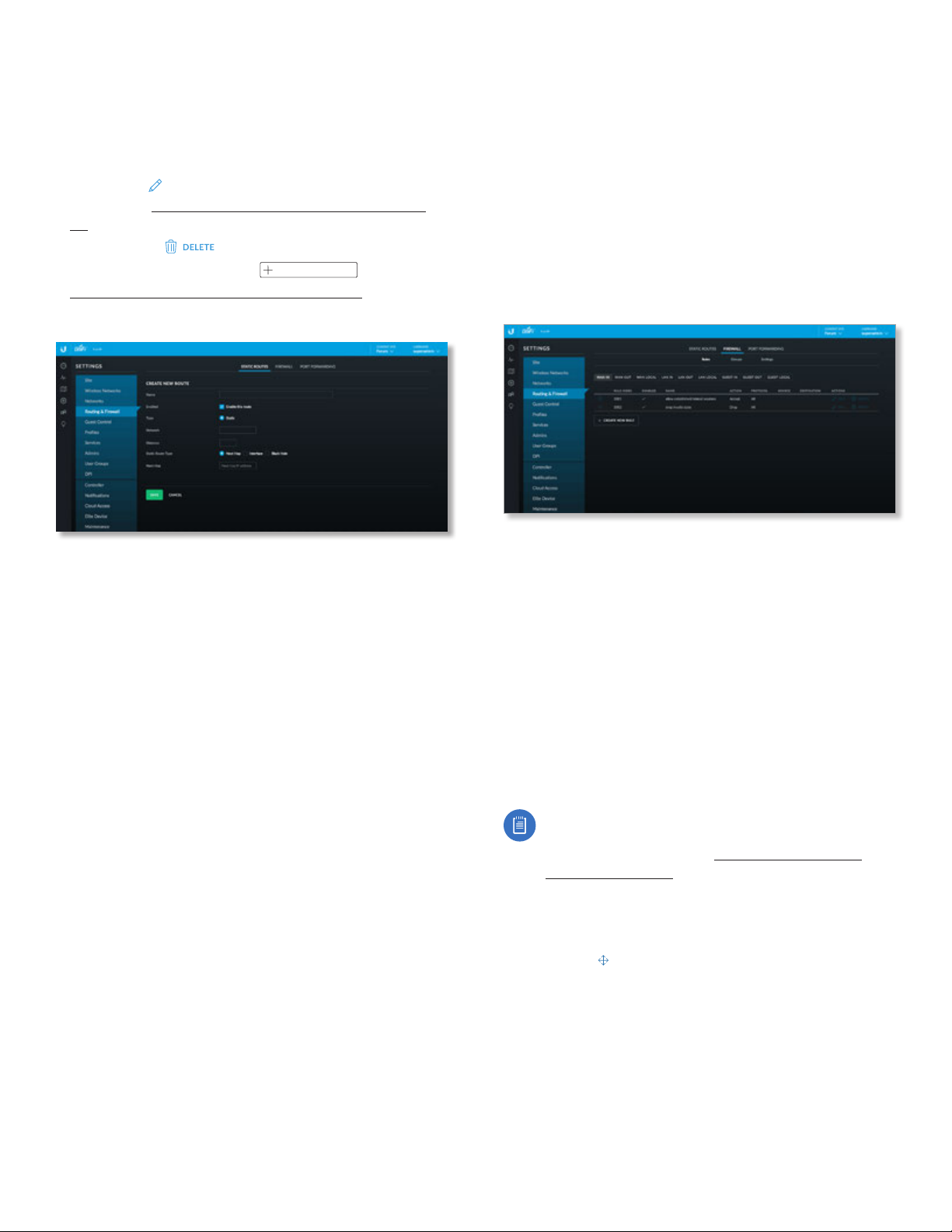
Chapter 3: Using the UniFi Controller Software
UniFi Controller User Guide
Next Hop Displays the IP address of the next hop for the
static route.
Hop Distance Displays the status route’s administrative
distance.
Actions Click a button to perform the desired action:
• Edit Click
EDIT
to make changes to the static route
entry. Go to “Create or Edit a Static Route” on page
32.
• Delete Click
To create a static route, click
to remove the static route.
CREATE NEW ROUTE
and go to
“Create or Edit a Static Route” on page 32 .
Create or Edit a Static Route
Firewall
Firewall rules are used to allow or block packets on an
interface. There are predefined rules that cannot be edited
or deleted, and you can create your own rules. When you
create a rule, you specify matching criteria, such as the
protocol (any, TCP, UDP, etc.) and whether the rule will be
evaluated before or after the predefined rules. Rules are
evaluated in order; as soon as one rule results in a match,
that rule is applied, and rule evaluation stops.
The Firewall tab displays user-defined firewall information,
organized into three sub-tabs: Rules, Groups, and Settings.
Rules
Name Enter a name for the static route.
Enabled Keep this option selected to enable the route.
The route is enabled by default.
Type This read-only field displays the route type: Static.
Network Enter the IP address and subnet mask using
CIDR or slash notation:
<network_IP_address>/<subnet_mask_number>
(example: 192.0.2.0/24).
Distance Enter the static route’s administrative distance.
This is a number between 1 and 255. This number is often
set to 1 (or a similarly low value) to create a route with a
shorter distance than dynamic routes.
Static Route Type Select the static route’s type: Next
Hop, Interface, or Black Hole.
• Next Hop The IP address of the next hop gateway for
the desired routing path. This is the default.
- Next Hop Enter the next hop IP address.
• Interface Interface routes are used with point-to-point
connections, where there need not be a gateway IP.
They are most often used with VPNs.
- Interface Select the appropriate interface.
• Black Hole Select this option to forward unwanted
traffic into a black hole, or to drop it.
Save Click to apply changes.
Cancel Click to discard changes.
The Rules sub-tab displays existing firewall rules. There are
three network types:
WAN This is your internet connection.
LAN This is in reference to all corporate networks.
Guest This is in reference to any guest subnets.
There are three instances per network type: In, Out, and
Local:
In Filters packets that enter the interface and traverse the
router.
Out Filters packets that leave the interface. This applies to
traffic that traverses the system or from the router itself.
Local Filters packets that are destined for the router.
Note: There are predefined firewall rules for most
interfaces. For detailed information on these
predefined rules, refer to “Predefined Firewall
Rules” on page 33.
The interfaces are WAN In, WAN Out, WAN Local, LAN In, LAN
Out, LAN Local, Guest In, Guest Out, and GUEST Local.
The following information is displayed for each rule:
(order) Click to change the order of the rules (except
for the predefined rules).
Rule Index Displays an automatically generated index
number associated with the rule.
Enabled Displays a check mark if the rule is enabled.
Name Displays the descriptive name of the rule.
Action Displays the action to take if the rule criteria are
satisfied: Drop, Reject, or Accept.
32
Ubiquiti Networks, Inc.
Page 39
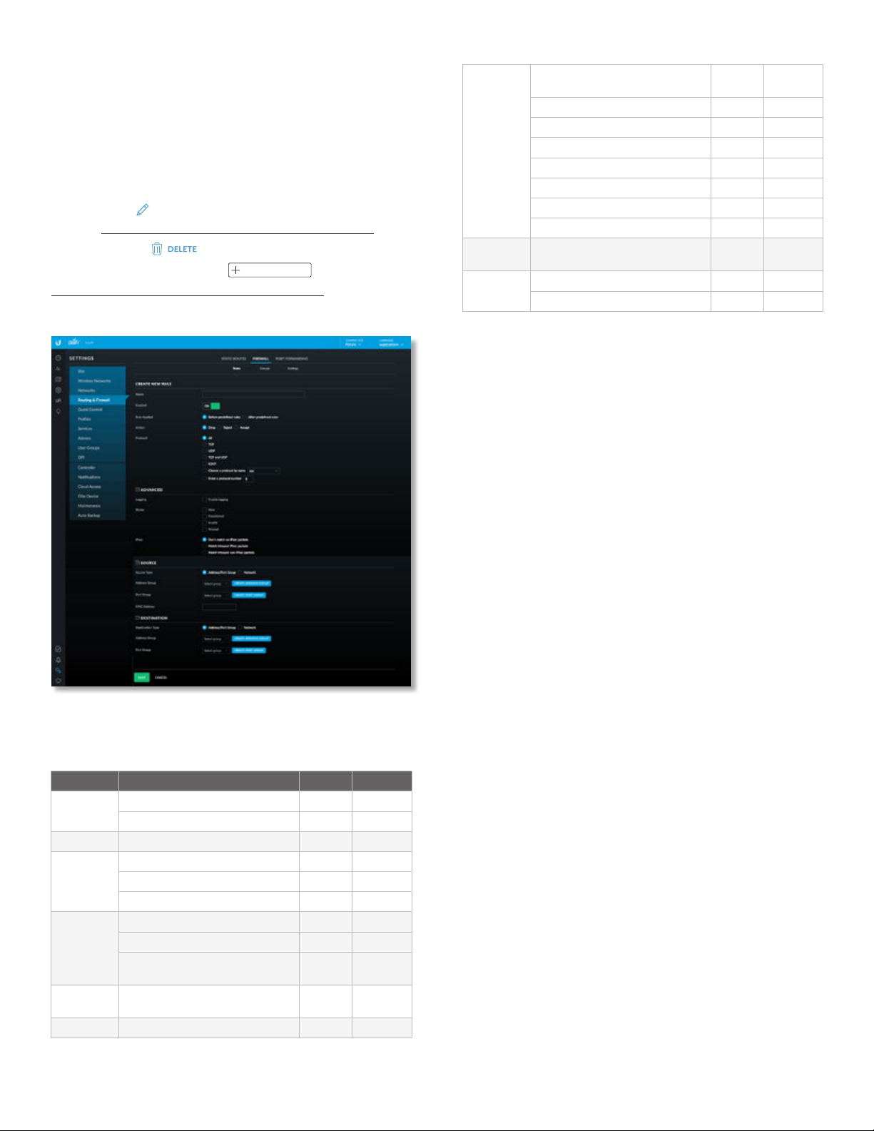
UniFi Controller User Guide
EDIT
Chapter 3: Using the UniFi Controller Software
Protocol Displays the protocol(s) that apply to the rule. If
Except: precedes the listed protocol(s), all protocols except
those listed are applicable.
Source Displays the source to which the rule applies.
Destination Displays the destination to which the rule
applies.
Actions Click a button to perform the desired action:
• Edit Click
to make changes to the firewall rule.
Go to “Create or Edit a Firewall Rule” on page 33.
• Delete Click
To create a firewall rule, click
to remove the firewall rule.
CREATE NEW RULE
and go to
“Create or Edit a Firewall Rule” on page 33.
Create or Edit a Firewall Rule
Predefined Firewall Rules
The following firewall rules are predefined (cannot be
edited or deleted):
Interface Rule Name Action Protocol
WAN IN Allow established/related sessions Accept All
Drop invalid state Drop All
WAN OUT None* - -
WAN
LOCAL
LAN IN Packets from UniFi to VoIP Accept All
LAN OUT Accounting defined network
LAN LOCAL None - -
Allow established/related sessions Accept All
Drop invalid state Drop All
Allow ICMP Accept ICMP
Packets from Intranet to VoIP Drop All
Accounting defined network
192.168.1.0/24
192.168.1.0/24
Accept All
Accept All
GUEST IN Allow DNS packets to external
GUEST
OUT
GUEST
LOCAL
* The WAN_OUT ruleset is not deployed by default until controller
version 5.5.2 and newer. To deploy WAN_OUT in earlier versions, set
config.ugw.deploy_firewall_wan_out=true in config.properties.
name servers
Allow packets to captive portal Accept TCP
Allow packets to allow subnets Accept All
Drop packets to restricted subnets Drop All
Drop packets to intranet Drop All
Drop packets to voip Drop All
Drop packets to remote user Drop All
Authorized guests white list Drop All
None - -
Allow DNS Accept UDP
Allow ICMP Accept ICMP
Accept UDP
Create New Rule
Name Enter a descriptive name for the rule.
Enabled Enables or disables the rule (enabled by default).
Rule Applied Specify when the rule will be applied:
Before Predefined Rules (default) or After Predefined
Rules.
Action Select the action to take if the rule criteria are
satisfied:
• Drop Packets are blocked with no message. This is the
default action.
• Reject Packets are blocked, and an ICMP (Internet
Control Message Protocol) message is sent saying that
the destination is unreachable.
• Accept Packets are allowed through the firewall.
Protocol Specify the protocol(s) to which the rule applies.
Select one of the following:
• All Match packets of all protocols (default).
• TCP Match TCP packets.
• UDP Match UDP packets.
• TCP and UDP Match TCP and UDP packets.
• ICMP Match ICMP packets.
• Choose a protocol by name Select a protocol from the
drop-down list to match packets of that protocol.
• Enter a protocol number Enter the port number of the
protocol to match packets of that protocol.
• Match all protocols except for this Match all protocols
except for the selected protocol(s). (At least one protocol
must be selected; All is not a valid selection with this
option.)
• ICMP Type Name (Available if ICMP is selected.) Select
the appropriate type from the drop-down list.
Ubiquiti Networks, Inc.
33
Page 40
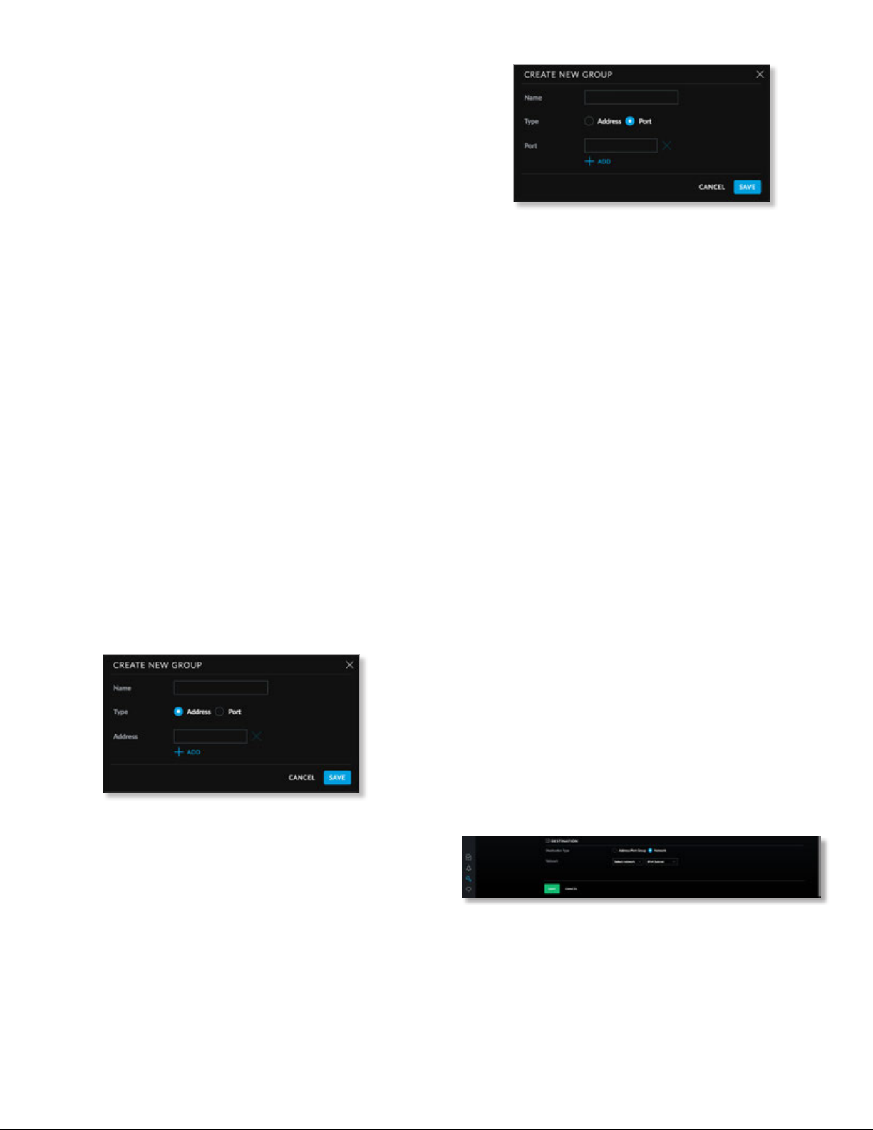
Chapter 3: Using the UniFi Controller Software
Advanced
Logging Check the box to enable logging (disabled by
default).
States Select each state that will apply to the rule (none
are selected by default).
• New The packet is the first packet seen in a new
connection.
• Established The packet is part of an existing
connection which has seen packets in both directions.
• Invalid The packet cannot be identified or its state
cannot be determined.
• Related The packet is part of a new connection that is
related to an existing connection.
IPsec Select the criteria for IPsec packet filtering:
Don’tmatch on IPsec packets (default), Match inbound
IPsec packets, or Match inbound non-IPsec packets.
Source
Source Type Select Address/Port Group or Network.
• Address/Port Group The source is an address/port
group. Specify the following:
- Address Group Select an address group from the
drop-down list. To create a new address group, click
Create Address Group.
• Name Enter a descriptive name.
• Address Enter an IP address.
• Add Toadd another address to the group, click
Add.
• Save Click to apply changes.
• Cancel Click to discard changes.
- Port Group Select a port group from the drop-down
list. To create a new address group, click Create Port
Group.
• Name Enter a descriptive name.
• Port Enter a port number.
• Add Toadd another port number to the group,
click Add.
• Save Click to apply changes.
• Cancel Click to discard changes.
UniFi Controller User Guide
• Network The source is a network. Specify the following:
- Network Select the network from the drop-down list.
Then select IPv4 Subnet or USG IP Address from the
drop-down list.
MAC Address Enter the MAC address of the source.
Destination
Destination Type Select the type of destination:
• Address/Port Group The destination is an address/port
group. Specify the following:
- Address Group Select an address group from the
drop-down list. To create a new address group, click
Create Address Group.
• Name Enter a descriptive name.
• Address Add an IP address.
• Add Toadd another address to the group, click
Add.
• Save Click to apply changes.
- Port Group Select a port group from the drop-down
list. To create a new address group, click Create Port
Group.
• Name Enter a descriptive name.
• Port Enter a port number.
• Add Toadd another port number to the group,
click Add.
• Save Click to apply changes.
• Network The destination is a network. Specify the
following:
- Network Select the network from the drop-down list.
Then select IPv4 Subnet or USG IP Address from the
drop-down list.
Save Click to apply changes.
Cancel Click to discard changes.
34
Ubiquiti Networks, Inc.
Page 41
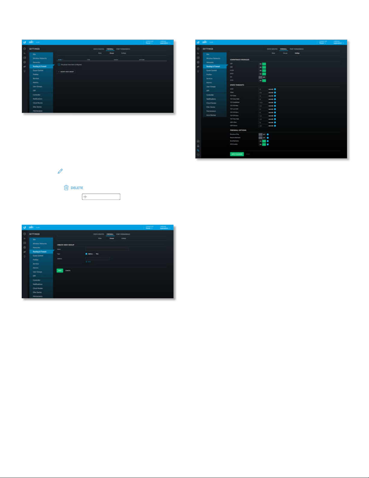
UniFi Controller User Guide
Chapter 3: Using the UniFi Controller Software
Groups
The Groups sub-tab displays the following information:
Name Displays the name of the group.
Type Displays the group type: Address or Port.
Count Displays the total addresses or ports in the group.
Actions Click a button to perform the desired action:
• Edit Click
EDIT
to make changes to the group. Go to
the Create or Edit a Firewall Group section.
• Delete Click
To create a group, click
to remove the group.
CREATE NEW GROUP
and go to the
Create or Edit a Firewall Group section.
Create or Edit a Firewall Group
Name Enter a name for the group.
Type Select the type of group to create: Address or Port.
Address (Available if Type is set to Address.) Enter the IP
address.
Port (Available if Type is set to Port.) Enter the port
number.
Add Click Add to add another address or port to the
group.
Save Click to apply changes.
Cancel Click to discard changes.
Settings
The Settings sub-tab displays the following options:
Conntrack Modules
FTP Tracks FTP connections. Enabled by default.
GRE Tracks GRE connections. Enabled by default.
H.323 Tracks H.323 connections. Enabled by default.
PPTP Tracks PPTP connections. Enabled by default.
SIP Tracks SIP connections. Disabled by default.
TFTP Tracks TFTP connections. Enabled by default.
State Timeouts
ICMP Enter the ICMP state timeout in seconds. The
default is 30.
Other Enter the state timeout for protocols excluding TCP,
UDP, and ICMP in seconds. The default is 600.
TCP Close Enter the ICMP state timeout in seconds. The
default is 10.
TCP Close Wait Enter the state timeout in seconds for
connections in TCP Close Wait status. The default is 60.
TCP Established Enter the state timeout in seconds for
connections in TCP Established status. The default is 7440.
TCP FIN Wait Enter the state timeout in seconds for
connections in TCP FIN Wait status. The default is 120.
TCP Last ACK Enter the state timeout in seconds for
connections in TCP Last ACK status. The default is 30.
TCP SYN Recv Enter the state timeout in seconds for
connections in TCP SYN (Synchronize) Recv status. The
default is 60.
TCP SYN Sent Enter the state timeout in seconds for
connections in TCP SYN Sent status. The default is 120.
TCP Time Wait Enter the state timeout in seconds for
connections in TCP Time Wait status. The default is 120.
UDP Other Enter the state timeout in seconds for UDP
connections with traffic in only one direction. The default
is 30.
Ubiquiti Networks, Inc.
35
Page 42
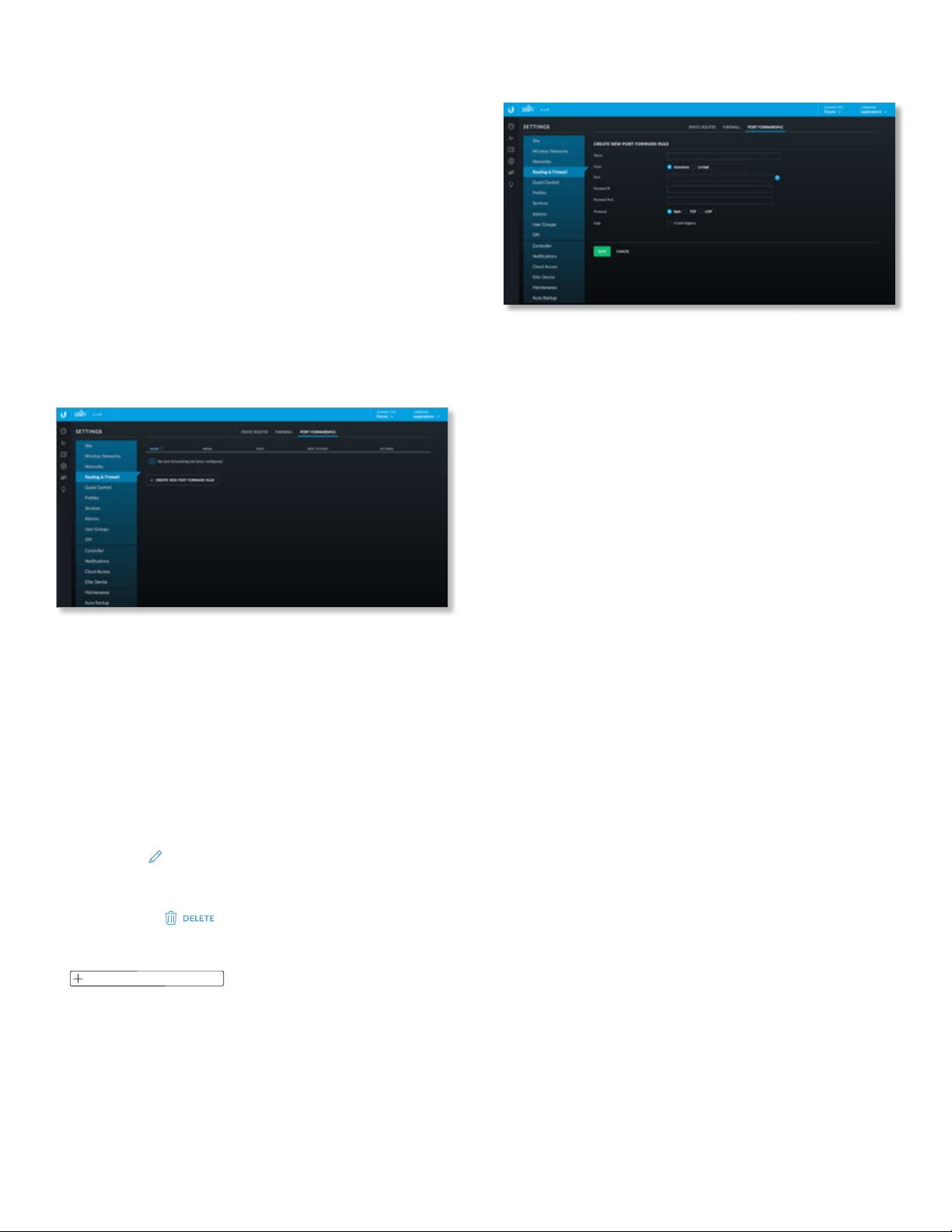
Chapter 3: Using the UniFi Controller Software
UniFi Controller User Guide
UDP Stream Enter the state timeout in seconds for UDP
connections with bidirectional traffic. The default is 180.
Firewall Options
Broadcast Ping Controls whether the UniFi Security
Gateway replies to broadcast pings. Disabled by default.
Receive Redirects Controls whether the UniFi Security
Gateway accepts ICMP redirects. Disabled by default.
Send Redirects Controls whether the UniFi Security
Gateway sends ICMP redirects. Enabled by default.
SYN Cookies Controls usage of SYN cookies, a technique
to resist SYN flood attacks that want to open ports on the
UniFi Security Gateway. Enabled by default.
Apply Changes Click to save changes.
Reset Click to discard changes.
Port Forwarding
The Port Forwarding tab displays a list of port forwarding
entries.
Name Displays the name of the port forwarding entry.
From Displays the source IP address, if specified.
Port Displays the port or ports that will be forwarded to
the LAN. Also known as the external port(s).
Dest IP/Port Displays the destination IP address and
port(s) that will receive the forwarded port traffic. Also
known as the internal port(s).
Actions Click a button to perform the desired action:
• Edit Click
forwarding entry. Go to the Create or Edit a Port
Forwarding Entry section.
• Delete Click
entry.
To create a port forwarding rule, click
CREATE NEW PORT FORWARD RULE
Port Forwarding Entry section.
EDIT
to make changes to the port
to remove the port forwarding
and go to the Create or Edit a
Create or Edit a Port Forwarding Entry
Name Enter a name to identify this port forwarding entry.
From The default is Anywhere, which accepts traffic from
any source IP address. To specify a source IP address,
select Limited and enter the source IP address in the field
provided.
Port Enter the port or ports that will be forwarded to the
LAN (also known as the external port or ports). You can
identify the port or ports by name, number, and/or range.
To specify multiple ports, use a comma-separated list
(example: 20‑23,554).
Forward IP Enter the LAN IP address that will receive the
forwarded port traffic.
Forward Port Enter the port or ports that will receive
the forwarded port traffic (also known as the internal
port). You can identify the port or ports by name, number,
and/or range. If you do not specify this port, then the
original destination port of the traffic will beused.
Protocol Select the protocol that will be forwarded: Both,
TCP, or UDP.
Logs Select this option to create port forward logs.
Save Click to apply changes.
Cancel Click to discard changes.
36
Ubiquiti Networks, Inc.
Page 43
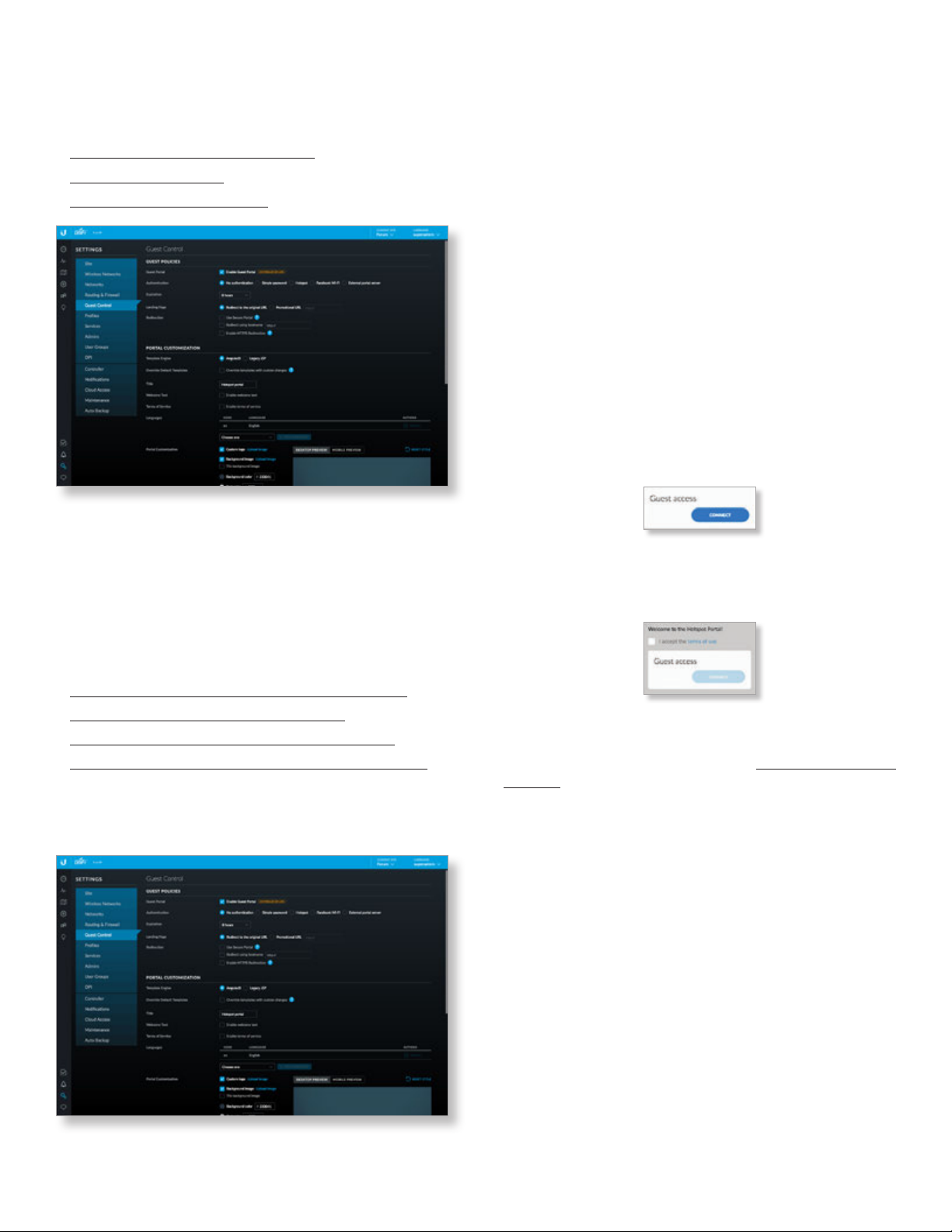
UniFi Controller User Guide
Chapter 3: Using the UniFi Controller Software
Settings > Guest Control
The Guest Control screen displays the following sections:
• Guest Policies (see below)
• “Portal Customization” on page 40
• “Hotspot” on page 41 (for Hotspot authentication)
• “Access Control” on page 45
Guest Policies
Enable Guest Portal Disabled by default. When disabled,
guests can access the internet without entering a
password or accepting the terms of service. When this
option is enabled, you can control the Guest Portal.
Authentication When the Guest Portal is enabled, the
authentication options will appear:
• Authentication > No Authentication
• “Authentication > Simple Password” on page 38
• “Authentication > Hotspot” on page 38
• “Authentication > Facebook Wi-Fi” on page 39
• “Authentication > External Portal Server” on page 39
Authentication > No Authentication
Select this option if guests are not required to log in (you
can choose to require the terms of service).
Expiration Specify the guest login expiration after a
designated period of time: 8 hours, 24hours, 2 days,
3 days, 4 days, 7 days, or User-defined, which can be
designated in minutes, hours, or days.
Landing Page After connecting, guests are redirected to
the landing page. Select one of the following options:
• Redirect to the original URL After connecting, guests
are directed to the URL they requested.
• Promotional URL After connecting, guests are
redirected to the URL that you specify. Ensure that the
URL begins with http://. Example: http://www.ubnt.com
Use Secure Portal When selected, unauthorized guests
will be redirected to the HTTPS guest portal.
Redirect Using Hostname Select this option to enter and
use a hostname for the portal URL in place of the default
IP address. Paired with an SSL certificate, this ensures
that site certificates are displayed as trusted in the guest
browser. Example: www.ubnt.com
When logging in with No authentication, guests can click
Connect for immediate access.
If you enable the terms of service, then guests will be
required to accept the terms of use before gaining access
to the internet.
You can select Enable terms of service under Settings >
Guest Control > Portal Customization to enforce selection of
the terms of service by the guest. See “Access Control” on
page 45 for more information.
Enable HTTPS Redirection When selected, unauthorized
guests will be redirected to the guest portal when they are
HTTPS browsing.
Ubiquiti Networks, Inc.
37
Page 44
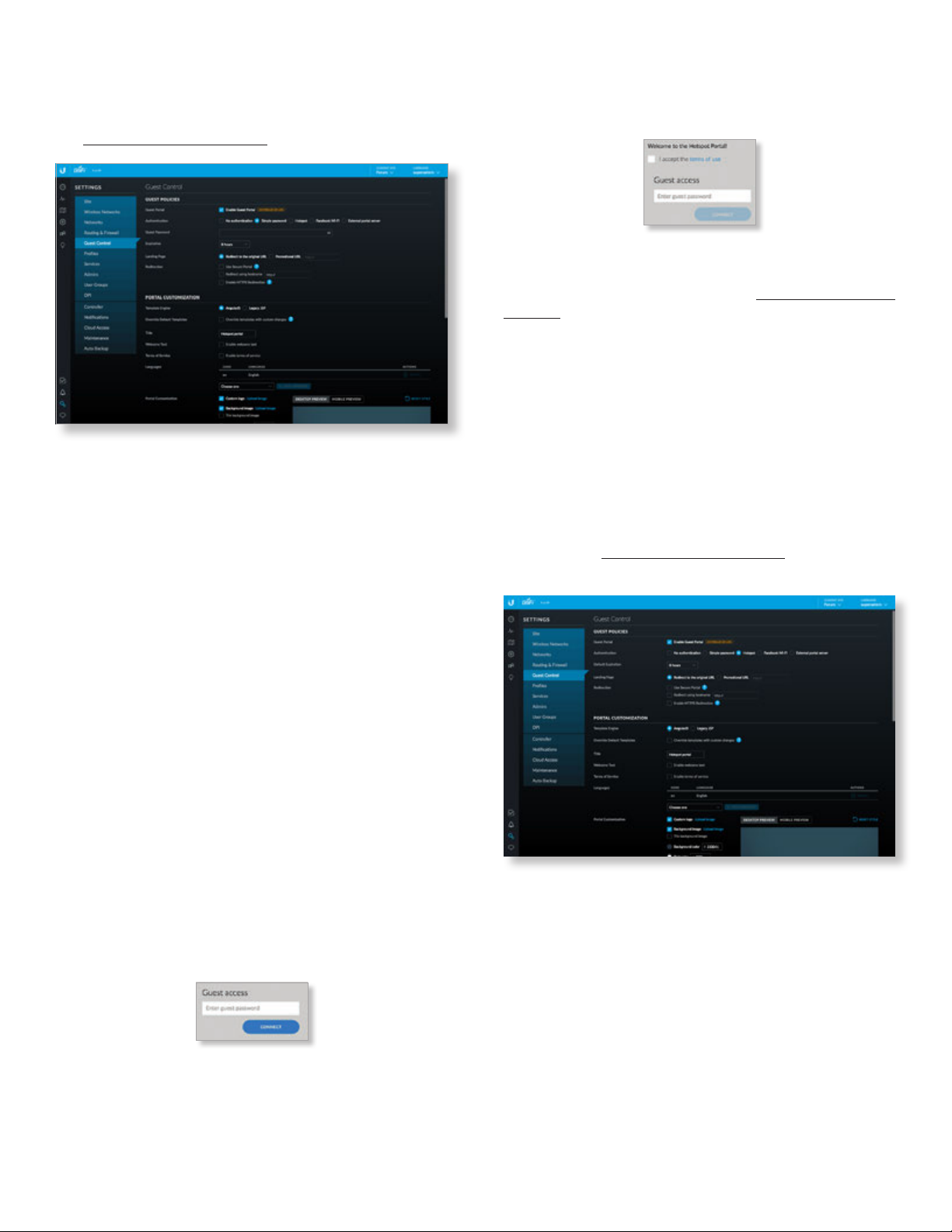
Chapter 3: Using the UniFi Controller Software
UniFi Controller User Guide
Authentication > Simple Password
Select this option if guests are required to enter a simple
password (you can choose to require the terms of service).
See “Guest Policy” on page 24 for more information.
Guest Password Enter a password that guests must enter
before connecting to the internet.
Expiration Specify the guest login expiration after a
designated period of time: 8 hours, 24hours, 2 days,
3 days, 4 days, 7 days, or User-defined, which can be
designated in minutes, hours, or days.
Landing Page After connecting, guests are redirected to
the landing page. Select one of the following options:
• Redirect to the original URL After connecting, guests
are directed to the URL they requested.
• Promotional URL After connecting, guests are
redirected to the URL that you specify. Ensure that the
URL begins with http://. Example: http://www.ubnt.com
Use Secure Portal When selected, unauthorized guests
will be redirected to the HTTPS guest portal. If you don’t
have a valid certificate installed on the UniFi Controller,
then guests will see a certificate error and the Captive
Network Assistant on OS X may not appear.
Redirect Using Hostname Select this option to enter and
use a hostname for the portal URL in place of the default
IP address. Paired with an SSL certificate, this ensures
that site certificates are displayed as trusted in the guest
browser. Example: www.ubnt.com
When logging in with Simple Password authentication,
guests will be required to enter the Guest Password before
gaining access to the internet.
If you enable the terms of service, then guests will be
required to accept the terms of use before gaining access
to the internet.
You can select Enable terms of service under Settings >
Guest Control > Portal Customization to enforce selection of
the terms of service by the guest. See “Access Control” on
page 45 for more information.
Enable HTTPS Redirection When selected, unauthorized
guests will be redirected to the guest portal when they are
HTTPS browsing. They may see an invalid certificate error
if they are HTTPS browsing before authentication.
Authentication > Hotspot
Select this option to enable Hotspot functionality,
including the ability to customize portal login pages
and bill customers using major credit cards or other
supported methods. You must also select Enable Guest
Portal under Settings > Guest Control to enforce voucher
entry, payment, and selection of the terms of service by
the guest. See “Guest Policy” on page 24 for more
information.
Default Expiration Specify the guest login expiration
after a designated period of time: 8 hours, 24hours,
2days, 3 days, 4 days, 7 days, or User-defined, which can
be designated in minutes, hours, or days.
Landing Page After connecting, guests are redirected to
the landing page. Select one of the following options:
• Redirect to the original URL After connecting, guests
are directed to the URL they requested.
• Promotional URL After connecting, guests are
redirected to the URL that you specify. Ensure that the
URL begins with http://. Example: http://www.ubnt.com
38
Ubiquiti Networks, Inc.
Page 45
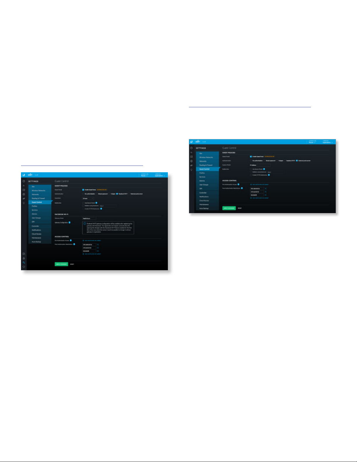
UniFi Controller User Guide
Chapter 3: Using the UniFi Controller Software
Use Secure Portal When selected, unauthorized guests
will be redirected to the HTTPS guest portal. If you don’t
have a valid certificate installed on the UniFi Controller,
then guests will see a certificate error and the Captive
Network Assistant on OS X may not appear.
Redirect Using Hostname Select this option to enter and
use a hostname for the portal URL in place of the default
IP address. Paired with an SSL certificate, this ensures
that site certificates are displayed as trusted in the guest
browser. Example: www.ubnt.com
Enable HTTPS Redirection When selected, unauthorized
guests will be redirected to the guest portal when they are
HTTPS browsing. They may see an invalid certificate error
if they are HTTPS browsing before authentication.
Authentication > Facebook Wi-Fi
Select this option to enable free Wi-Fi via Facebook, so
businesses can offer free Wi-Fi via Facebook check-in for
their customers. For more information, go to:
https://www.facebook.com/help/facebookwifi
Facebook Wi-Fi
Gateway Name Enter the name of your Facebook Wi-Fi
gateway.
Gateway Configuration You can configure the gateway
after you register it with Facebook. The registration will
happen automatically after applying the changes with the
Facebook Wi-Fi feature enabled for the first time. Once you
select the name, you cannot change it without registering
the gateway again.
For more information, go to:
https://www.facebook.com/help/facebookwifi
Authentication > External Portal Server
Select this option if you are using an external server to
host a custom guest portal.
Expiration Specify the guest login expiration after a
designated period of time: 8 hours, 24hours, 2days,
3 days, 4 days, 7 days, or User-defined, which can be
designated in minutes, hours, or days.
Use Secure Portal When selected, unauthorized guests
will be redirected to the HTTPS guest portal. If you don’t
have a valid certificate installed on the UniFi Controller,
then guests will see a certificate error and the Captive
Network Assistant on OS X may not appear.
Redirect Using Hostname Select this option to enter and
use a hostname for the portal URL in place of the default
IP address. Paired with an SSL certificate, this ensures
that site certificates are displayed as trusted in the guest
browser. Example: www.ubnt.com
Enable HTTPS Redirection When selected, unauthorized
guests will be redirected to the guest portal when they are
HTTPS browsing. They may see an invalid certificate error
if they are HTTPS browsing before authentication.
Custom Portal Enter the IP address in the IP Address field.
Use Secure Portal When selected, unauthorized guests
will be redirected to the HTTPS guest portal. If you don’t
have a valid certificate installed on the UniFi Controller,
then guests will see a certificate error and the Captive
Network Assistant on OS X may not appear.
Redirect Using Hostname Select this option to enter and
use a hostname for the portal URL in place of the default
IP address. Paired with an SSL certificate, this ensures
that site certificates are displayed as trusted in the guest
browser. Example: www.ubnt.com
Enable HTTPS Redirection When selected, unauthorized
guests will be redirected to the guest portal when they are
HTTPS browsing. They may see an invalid certificate error
if they are HTTPS browsing before authentication.
Ubiquiti Networks, Inc.
39
Page 46
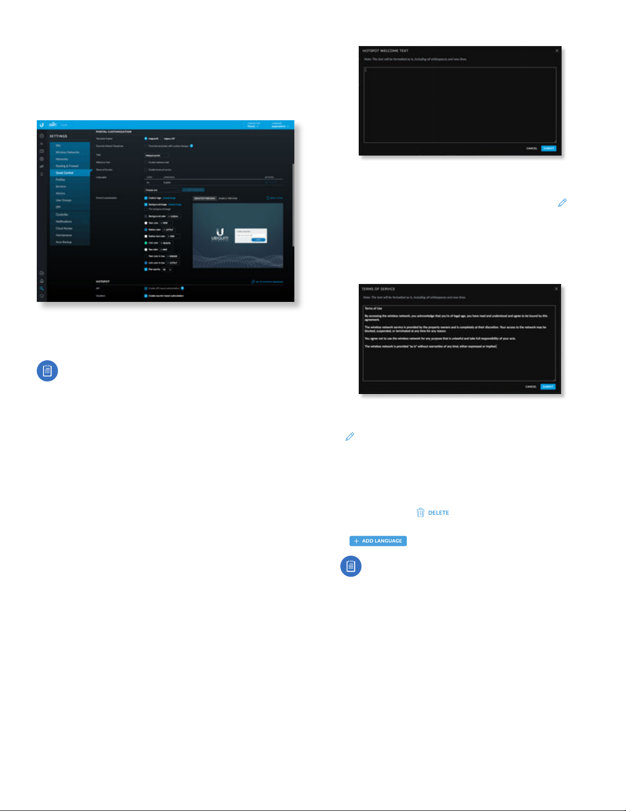
Chapter 3: Using the UniFi Controller Software
Portal Customization
Select this option to have customized portal pages appear
in place of the default login pages. (This option is not
available if you are using Facebook Wi-Fi or an external
portal server.)
Template Engine Select AngularJS for client-side
rendering or Legacy JSP for server-side rendering. We
recommend AngularJS unless you are using old templates.
UniFi Controller User Guide
After you have added your welcome text, click Submit
to save your changes or click Cancel.
Once you have welcome text, then you can click
EDIT
to make changes.
- Text position Select the appropriate location for the
welcome text, Under the logo or Above boxes.
• Terms of Service Select Enable terms of service to add
any terms of service you want hotspot users to accept.
Note: AngularJS is not compatible with old
templates because the old templates were designed
to work with JSP (Java Server Pages).
The UniFi Controller offers a built-in editor to customize
AngularJS; however, it is not fully customizable at
thistime.
AngularJS is a single-page app, so it should work more
quickly. However, AngularJS uses JS (JavaScript), which
may not work with some really old web browsers or newer
browsers with JS support disabled.
AngularJS uses responsive design, so it will adapt to the
size of a mobile device, such as a tablet or smartphone.
Legacy JSP is fully customizable and uses old HTML, so it
should work with any web browser. You can customize
Legacy JSP only by overriding files. Legacy JSP works more
slowly and is not responsive by default.
AngularJS
Select AngularJS for client-side rendering.
• Override Default Templates Select this option if you
want to manually edit the styles or templates. Please
note that changing the templates may mean that some
of the fields available in the UI will no longer apply to
the portal.
• Title Enter the title of your portal. The default is Hotspot
portal.
• Welcome Text Select Enable welcome text to add a
welcome message.
Click Submit to save your changes or click Cancel.
Once you have the terms of service, then you can click
EDIT
to make changes.
• Languages Displays the languages you have added.
English is the default and cannot be deleted.
- Code Displays the language code.
- Language Displays the name of the language.
- Actions Click
to remove the language.
- Add Language To add a language, select it and click
.
Note: Some languages are not supported
by default, so you will need to create a
locales/<code>/ directory in your overrides path
and translate the appropriate language files.
• Portal Customization You can make the following
formatting changes:
- Customize logo Click Upload image and select the
logo you want to use. (We recommend the use of the
.png format.) Then click Open.
- Background image Click Upload image and select
the image you want to use. (We recommend the use
of the .jpg format.) Then click Open.
• Tile background image Select this option if you
want to repeat the background image in a tile
pattern.
40
Ubiquiti Networks, Inc.
Page 47
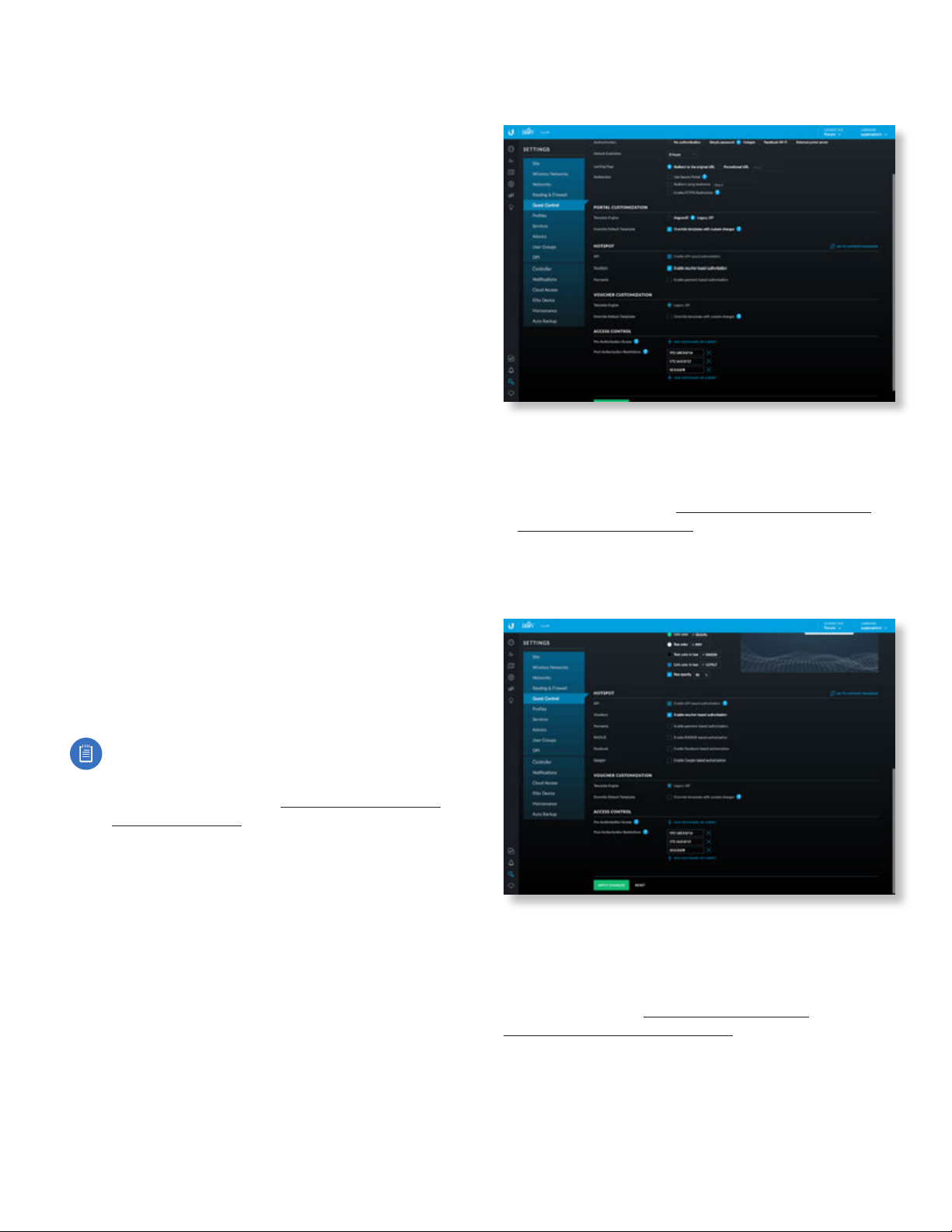
UniFi Controller User Guide
Chapter 3: Using the UniFi Controller Software
- Background color Click to select the appropriate
color, or enter the hexadecimal HTML color value you
want to use. The default is #233041.
- Text color Click to select the appropriate color, or
enter the hexadecimal HTML color value you want to
use. The default is #ffffff.
- Button color Click to select the appropriate color, or
enter the hexadecimal HTML color value you want to
use. The default is #1379b7.
- Button text color Click to select the appropriate
color, or enter the hexadecimal HTML color value you
want to use. The default is #ffffff.
- Link color Click to select the appropriate color, or
enter the hexadecimal HTML color value you want to
use. The default is #00db9e.
- Box color Click to select the appropriate color, or
enter the hexadecimal HTML color value you want to
use. The default is #ffffff.
- Text color in box Click to select the appropriate color,
or enter the hexadecimal HTML color value you want
to use. The default is #000000.
- Link color in box Click to select the appropriate color,
or enter the hexadecimal HTML color value you want
to use. The default is #1379b7.
- Box opacity You can change the opacity of the box
background color. The default is 90.
• Desktop Preview Enabled by default. The Desktop
Preview previews the portal in the desktop view.
• Mobile Preview Click Mobile Preview to preview the
portal in the mobile view.
• Reset Style Reset Portal Customization changes to the
factory defaults.
Legacy JSP
Select this option to enable server-side rendering.
• Override Default Templates Select this option if you
want to manually edit the styles or templates. Please
note that changing the templates may mean that
some of the fields available in the UI will no longer
apply to the portal. See “Portal Customization with
LegacyJSP” on page 157 for more information.
Hotspot
When Hotspot authentication is selected, the Hotspot
section is displayed.
Note: At this time AngularJS does not support
voucher customization; however, you can
customize vouchers using the voucher.html and
voucher.css files. Refer to “Customizable Default
Files” on page 160 for more information.
Ubiquiti Networks, Inc.
API API-based authorization is enabled by default.
Select the methods of authorization:
Vouchers Use Hotspot Manager to create vouchers
(including distributable code, duration values, and
use restrictions). See “Payments” on page 42 and
“Hotspot Manager” on page 151.
41
Page 48
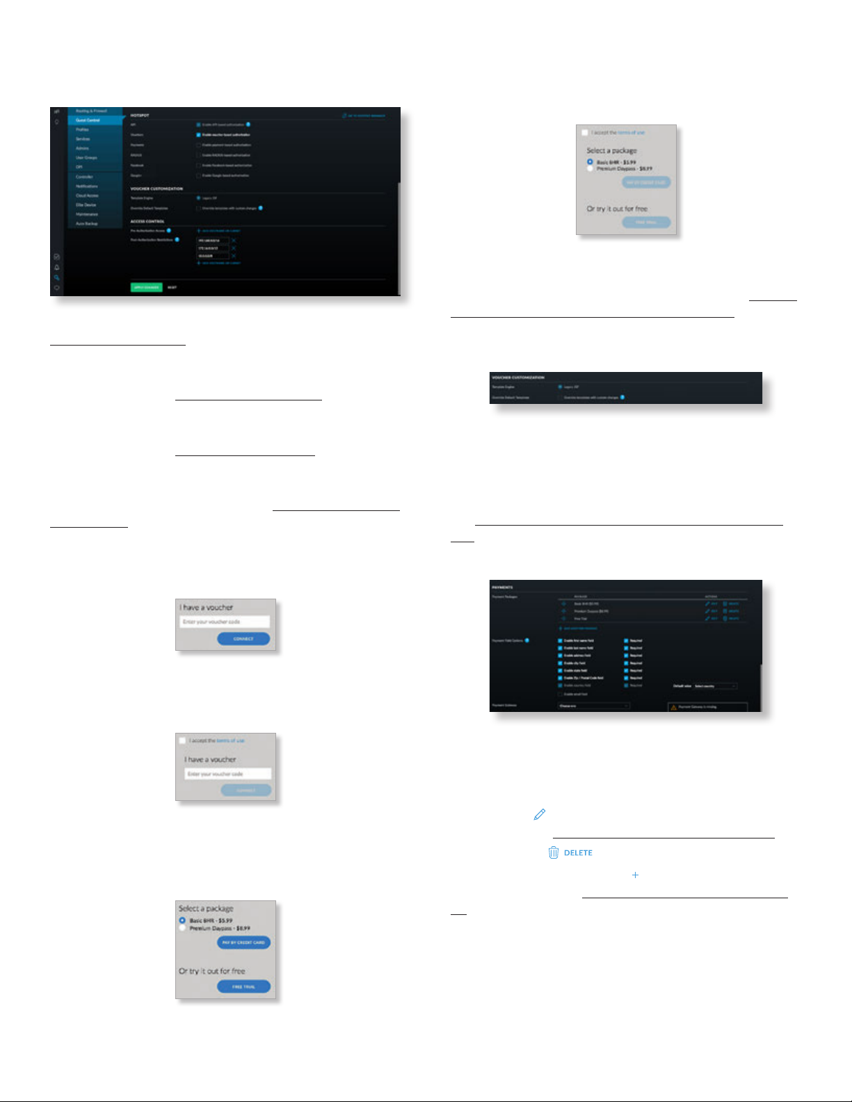
Chapter 3: Using the UniFi Controller Software
UniFi Controller User Guide
Payments Set up payment-based authentication. Go to
the Payments section.
RADIUS Available if AngularJS is enabled. Go to
“RADIUS” on page 48.
Facebook Available if AngularJS is enabled. This
authentication method requires Redirect using hostname
to be enabled. Go to ”Facebook” on page 45.
Google+ Available if AngularJS is enabled. This
authentication method requires Redirect using hostname
to be enabled. Go to “Google+” on page 45.
Go to Hotspot Manager Click Go to Hotspot Manager to
manage Analytics, Wireless Guests, Payments/Transactions,
Vouchers, and Operator Accounts. See “Hotspot Manager”
on page 151.
When logging in with voucher-based Hotspot
authentication, guests will be required to enter the
voucher number before gaining access to the internet.
If you enable the terms of service, then guests will be
required to accept the terms of use before gaining access
to the internet.
You can select Enable terms of service under Settings
> Guest Control > Portal Customization to enforce
selection of the terms of service by the guest. See “Portal
Customization with LegacyJSP” on page 157 for more
information.
Voucher Customization
Template Engine Legacy JSP is enabled by default.
Override Default Templates Select this option if you
want to manually edit the styles or templates. Please note
that changing the templates may mean that some of the
fields available in the UI will no longer apply to the portal.
See “Portal Customization with LegacyJSP” on page
157 for more information.
Payments
If you enable the terms of service, then guests will be
required to accept the terms of use before gaining access
to the internet.
When logging in with payment-based Hotspot
authentication, guests will be required to select the
package type and click the payment choice before gaining
access to the internet.
42
Payment Packages (Available only for payment-based
authentication.) There are three packages by default: Basic
8HR ($5.99), Premium Daypass ($8.99), and Free Trial.
Actions Click a button to perform the desired action:
• Edit Click
EDIT
to make changes to the package
settings. Go to “Add or Edit a Package” on page 43.
• Delete Click
Add Another Package Click
to delete the package.
ADD ANOTHER PACKAGE
to create
a new package. Go to “Add or Edit a Package” on page
43.
Ubiquiti Networks, Inc.
Page 49
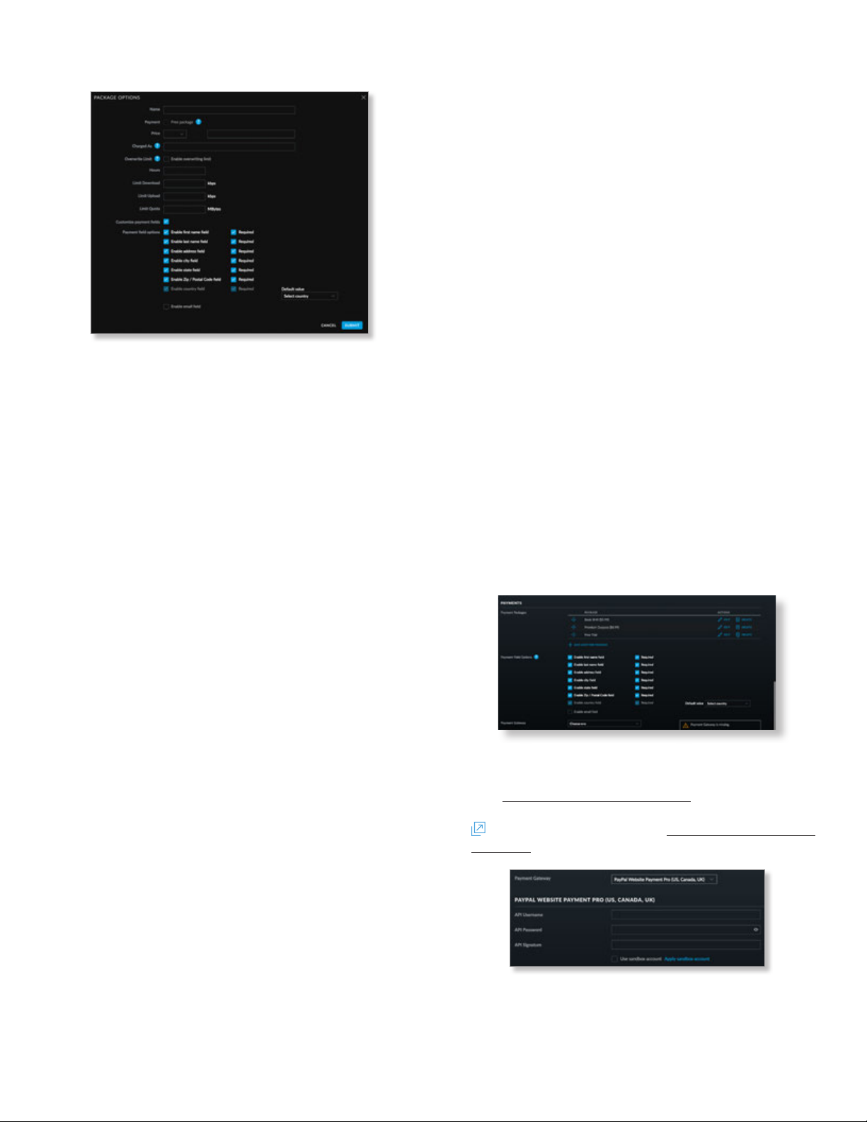
UniFi Controller User Guide
GO TO HOTSPOT MANAGER
Chapter 3: Using the UniFi Controller Software
Add or Edit a Package
• Name Enter or edit the name of the package.
• Payment Select Free package if appropriate. (Only
one free package is allowed. There is a free package
by default, so unless you delete it, this option is not
available.)
• Price Select the appropriate currency from the
drop-down menu, and then enter the price.
• Charged as Enter the text that will be shown on the
credit card statement.
• Overwrite Limit Select this option if you want to
overwrite the user group policy per WLAN/user.
• Hours Enter the number of access hours the package
allows.
• Limit Download Enter the maximum download
bandwidth in Kbps.
• Limit Upload Enter the maximum upload bandwidth in
Kbps.
• Limit Quota Enter the maximum amount (in
megabytes) of data transfer allowed per session.
• Customize payment fields Select to customize form
fields.
- Enable first name field Select this option to create a
field for a first name.
• Required Select this option if you want to make
this field mandatory.
- Enable last name field Select this option to create a
field for a last name.
• Required Select this option if you want to make
this field mandatory.
- Enable address field Select this option to create a
field for an address.
• Required Select this option if you want to make
this field mandatory.
- Enable city field Select this option to create a field
for a city.
• Required Select this option if you want to make
this field mandatory.
- Enable state field Select this option to create a field
for a state.
• Required Select this option if you want to make
this field mandatory.
- Enable Zip/Postal Code field Select this option to
create a field for a zip or postal code.
• Required Select this option if you want to make
this field mandatory.
- Enable country field Select this option to create a
field for a country.
• Required Select this option if you want to make
this field mandatory.
• Default value Select the appropriate default
country from the drop-down menu.
- Enable email field Select this option to create a field
for an email address.
• Required Select this option if you want to make
this field mandatory.
- Submit Click to apply changes.
- Cancel Click to discard changes.
Payment Field Options Certain fields may be required by
some payment gateways; please check with your payment
gateway for specific requirements. Refer to the Add or Edit
a Package section in the previous column for information
about the Payment Field Options.
Payment Gateway You have multiple options:
• PayPal™ Website Payment Pro (US, Canada,UK) Use
your PayPal Website Payments Pro
account.
To manage payments and transactions, click
, and see “Hotspot Manager” on
page 151.
Enter the PayPal account details:
- API Username Enter the corresponding Username.
- API Password Enter the corresponding Password.
Ubiquiti Networks, Inc.
43
Page 50
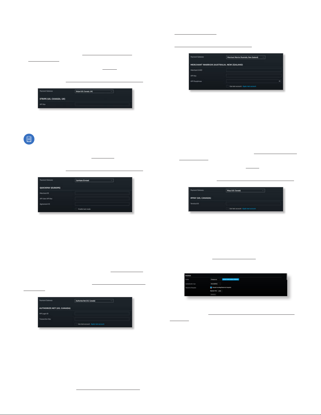
Chapter 3: Using the UniFi Controller Software
UniFi Controller User Guide
- API Signature Enter the corresponding Signature for
the PayPal account that will receive payments.
- Use sandbox account For PayPal testing purposes,
select this option. Then click Apply Sandbox Account
to set up or access your PayPal Sandbox Test
Environment.
• Stripe (US, Canada, UK) Use your Stripe account. To
manage payments and transactions, click Go to Hotspot
Manager, and see “Hotspot Manager” on page 151.
Enter the Stripe account detail:
- API Key Enter the live secret API key.
Note: We recommend that you perform a test
transaction with the test secret API key first before
using the live secret API key.
• Quickpay (Europe) Use your Quickpay account. To
manage payments and transactions, click Go to Hotspot
Manager, and see “Hotspot Manager” on page 151.
• Merchant Warrior (Australia, New Zealand) Use your
Merchant Warrior account. To manage payments and
transactions, click Go to Hotspot Manager, and see
“Hotspot Manager” on page 151.
Enter the Merchant Warrior account details:
- Merchant UUID Enter the ID for your merchant
account.
- API Key Enter the API key.
- API Passphrase Enter the API passphrase.
- Use test account For Merchant Warrior testing
purposes, select this option. Then click Apply Test
Account to set up or access your Merchant Warrior
test account.
• IPpay™ (US, Canada) Use your IPpay account. To
manage payments and transactions, click Go to Hotspot
Manager, and see “Hotspot Manager” on page 151.
Enter the Quickpay account details:
- Merchant ID Enter the ID for your merchant account.
- API User API Key Enter the API key.
- Agreement ID Enter the agreement ID.
- Enable test mode Select this option to use the test
mode.
• Authorize.Net® (US, Canada) Use your Authorize.Net
account. To manage payments and transactions, click Go
to Hotspot Manager, and see “Hotspot Manager” on
page 151.
Enter the Authorize.Net account details:
- API Login ID Enter the API login ID used to identify
yourself as an authorized user.
- Transaction Key Enter the key used to authenticate
transactions.
- Use test account For Authorize.Net testing purposes,
select this option. Then click Apply Test Account to
set up or access your Authorize.Net test account.
Enter the IPpay account details:
- Terminal ID Enter the terminal number for your
merchant account.
- Use test account For IPpay testing purposes, select
this option. Then click Apply Test Account to set up
or access your IPpay test account.
RADIUS
Profile Select the appropriate RADIUS profile or create
a new one; go to “Create or Edit a RADIUS Profile” on
page 45 for more information.
Authentication type Select MS-CHAPv2 or CHAP.
Disconnect Requests Select this option to accept
incoming disconnect requests.
• Receiver Port Enter the appropriate port number. The
default is 3799.
44
Ubiquiti Networks, Inc.
Page 51
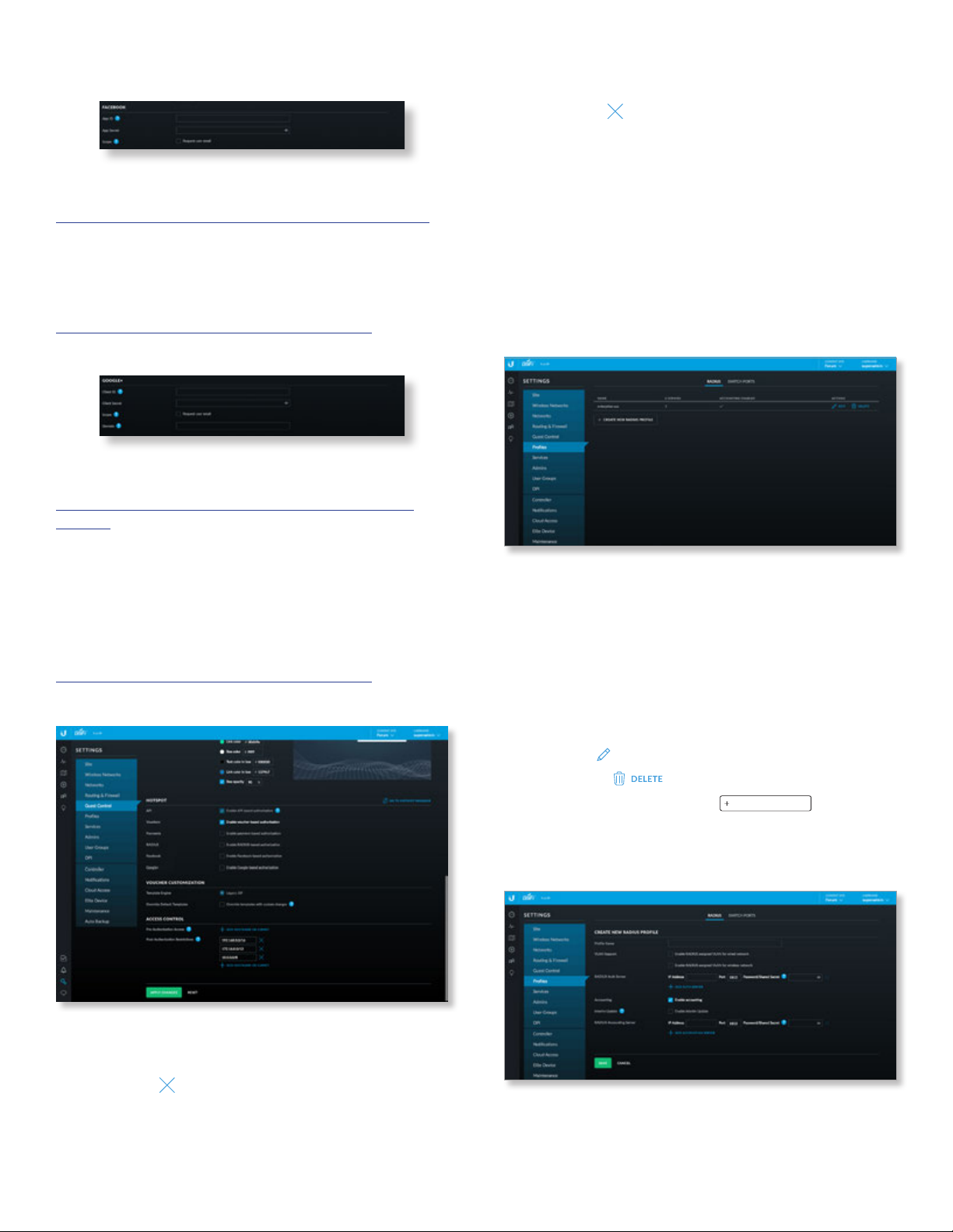
UniFi Controller User Guide
Chapter 3: Using the UniFi Controller Software
Facebook
App ID Enter the ID for the Facebook app. For more
information, go to:
https://developers.facebook.com/docs/apps/register
App Secret Enter the secret key.
Scope Select this option to request the user’s email
address.
For more information, go to:
ubnt.link/UniFi-Social-Media-Authentication
Google+
Client ID Enter the ID for the Google API. For more
information, go to:
https://developers.google.com/identity/protocols/
OAuth2
Client Secret Enter the secret key.
Scope Select this option to request the user’s email
address.
Domain Enter a domain to limit the connection to users
of a specific Google Apps domain.
For more information, go to:
ubnt.link/UniFi-Social-Media-Authentication
Access Control
Post-Authorization Restrictions Enter any hostnames or
subnets that you don’t want guests to be able to access.
Click the delete icon to remove a subnet from this list.
• Add Hostname or Subnet Click Add Hostname or
Subnet to add more restricted hostnames or subnets.
Apply Changes Click to save changes.
Reset Click to cancel changes.
Settings > Profiles
You can use this option to create profiles for RADIUS
authentication. RADIUS is a networking protocol providing
centralized Authentication, Authorization, and Accounting
(AAA) management for computers to connect to and use a
network service.
RADIUS
Name Displays the name of the RADIUS authentication
profile.
# Servers Displays the number of servers associated with
this profile.
Accounting Enabled Displays a check mark if RADIUS
accounting is enabled.
Actions Click a button to perform the desired action:
• Edit Click
• Delete Click
Add New RADIUS Profile Click
new RADIUS profile. The Create New RADIUS Profile screen
appears.
Create or Edit a RADIUS Profile
EDIT
to make changes.
to delete the profile.
CREATE NEW RADIUS PROFILE
to create a
Pre-Authorization Access Enter any hostnames or
subnets (internal or external) that you want guests to be
able to access, even if they have not been authenticated.
Click the delete icon to remove a subnet from this list.
• Add Hostname or Subnet Click Add Hostname or
Subnet to add more allowed hostnames or subnets.
Ubiquiti Networks, Inc.
Profile Name Enter a name for the RADIUS profile.
VLAN Support Use these options to configure VLAN
support:
45
Page 52
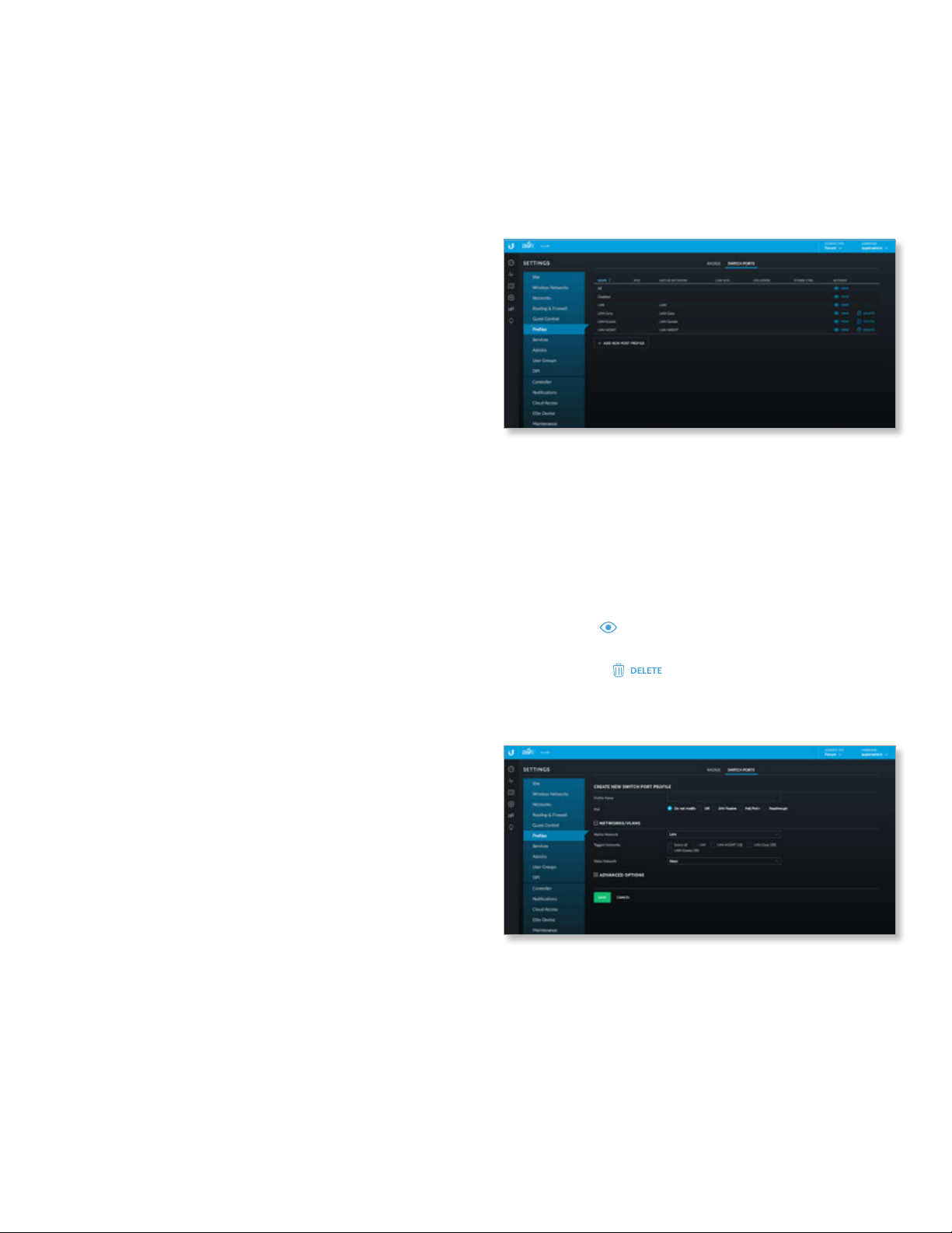
Chapter 3: Using the UniFi Controller Software
UniFi Controller User Guide
• Enable RADIUS assigned VLAN for Wired
Network Disabled by default. Select this option to
allow the RADIUS server to dynamically assign a VLAN to
a wired client.
• Enable RADIUS assigned VLAN for Wireless
Network Disabled by default. Select this option to
allow the RADIUS server to dynamically assign a VLAN to
a wireless client.
If you set a VLAN ID as a static value for another SSID on
the same AP, then you cannot re-use the same VLAN ID
for the RADIUS-assigned (dynamic) VLAN. For example,
if you have a VLAN set to VLAN 10, then you cannot use
VLAN ID 10 for RADIUS-controlled VLAN users as those
users will not be assigned an IP address.
RADIUS Auth Server Enter information used to identify
the RADIUS server(s):
• IP Address Enter the IP address of the RADIUS
authentication server.
• Port Enter the port number of the RADIUS
authentication server. The default is 1812.
• Password/Shared Secret Enter the password or
shared secret (a case-sensitive text string) that will
be used to validate communication with the RADIUS
authentication server.
• Add Auth Server Click to add another RADIUS
authentication server to the profile.
Accounting This option is disabled by default. If you are
using an accounting server, click Enable Accounting and
then configure the Interim Update and RADIUS Accounting
Server settings:
Interim Update To specify the duration between
accounting information updates, select Enable Interim
Update.
• Interim Update Interval Enter the appropriate
duration between updates for UniFi APs; the default is
3600 seconds.
RADIUS Accounting Server Configure the following
settings:
• IP Address Enter the IP address of the RADIUS
accounting server.
• Port Enter the port number of the RADIUS accounting
server. The default is 1813.
• Password/Shared Secret Enter the password or shared
secret (a case-sensitive text string) that will be used to
validate communication with the RADIUS accounting
server.
• Add Accounting Server Click to add another RADIUS
authentication server to the profile.
Save Click to apply changes.
Cancel Click to discard changes.
Switch Ports
You can define switch port profiles that specify VLAN
groupings for easy configuration. VLAN groupings
allow you to create a combination of native networks
(untagged) and tagged networks (tagged VLANs) for
switch ports. The groupings configured here are then
available for assignment to switch ports on the Switch’s
Port Configuration tab.
Name Displays the name of the profile.
PoE Displays the selected PoE option.
Native Network Displays the selected native network.
Link Neg. Displays the selected link negotiation option.
Isolation Displays the selected isolation option.
Storm Ctrl. Displays the selected storm control option.
Actions Click a button to perform the desired action:
• View Click
Create or View Switch Port Profile section.
• Delete Click
Add New Port Profile Click to create a new profile.
Create or View Switch Port Profile
• Profile Name Enter a name to identify this profile.
• PoE Select the appropriate option: Do not modify, Off,
24V Passive, PoE/PoE+, or Passthrough.
• Native Network The Native Network specifies the
default VLAN, or Port VLAN Identifier (PVID), for the
switch port. This determines the VLAN to be used for
untagged traffic on that port. Most client devices do not
VLAN-tag traffic; they will therefore only use the Native
Network on their port.
VIEW
to display more details. Go to the
to delete the entry.
46
Ubiquiti Networks, Inc.
Page 53
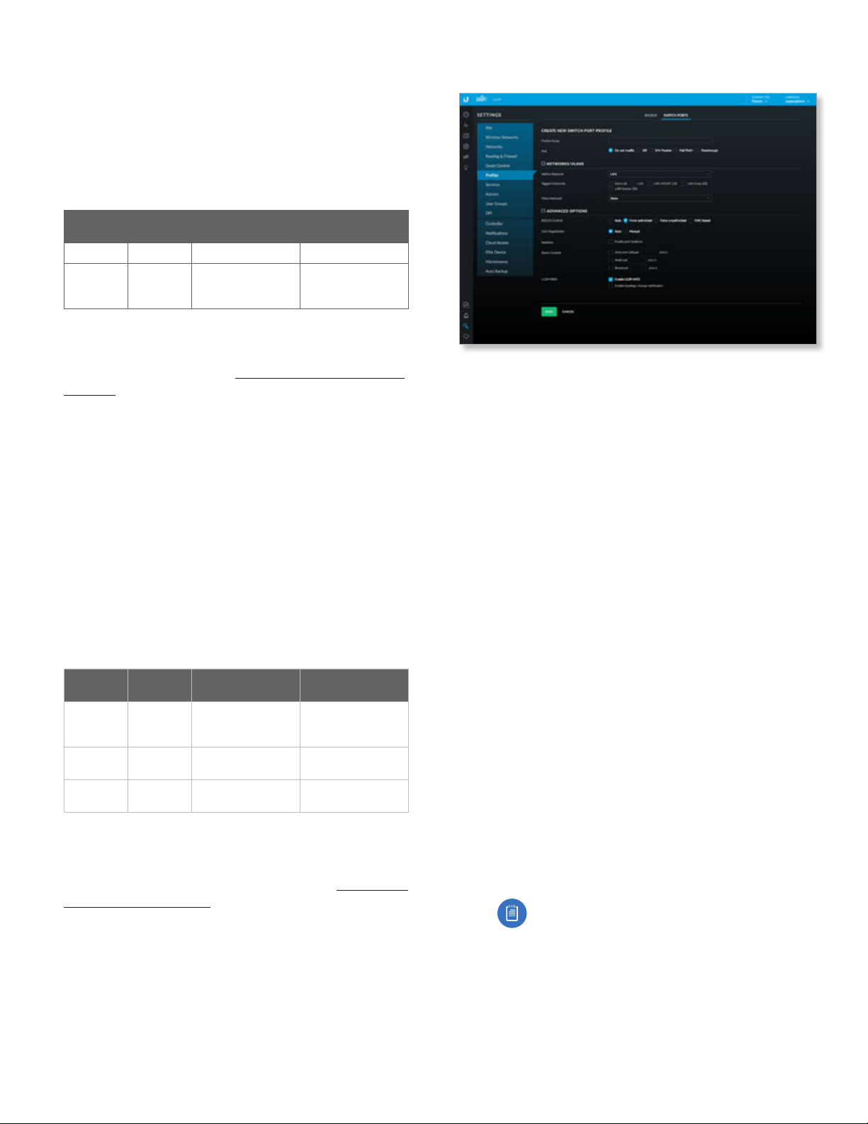
UniFi Controller User Guide
Chapter 3: Using the UniFi Controller Software
The Switch accepts tagged and untagged packets
in the ingress direction, and the untagged packets
are assigned to the VLAN of the native network. For
example, if the PVID is VLAN 30, then all untagged
packets are assigned to VLAN 30. In the egress direction,
the native network packets are stripped of the VLAN 30
header and exit as untagged packets.
This table lists how the packets are handled:
Packet
Type
Tagged Accepted Remains tagged Sent out as tagged
Untagged Accepted Assigned to VLAN
Ingress Action Egress
of native network
VLAN header
removed and sent
out as untagged
Each physical port can have multiple networks attached;
however, only one of them can be native (untagged).
Select the appropriate native network. (Additional
networks may be created in “Settings > Controller” on
page 56.)
• Tagged Networks The VLANs chosen here will be
permitted as tagged on switch ports configured with
this grouping. This permits ingress and egress traffic
with the applicable VLAN tag. Any VLAN tags other than
those chosen here will be dropped.
As an example, the following illustrates how an access
point’s switch port functions with one native network
and two tagged VLANs used for additional wireless
SSIDs. The AP’s switch port uses a VLAN grouping with
LAN (VLAN 1) as the native network, and has VLANs 20
and 30 defined as tagged networks.
• VLAN 20: corporate
• VLAN 30: guest
This table lists how the packets are handled:
Packet
Type
Untagged Accepted Assigned to VLAN 1 VLAN header
Tagged as
VLAN 20
Tagged as
VLAN 30
Ingress Action Egress
removed and sent
out as untagged
Accepted Remains tagged Sent out tagged as
VLAN 20
Accepted Remains tagged Sent out tagged as
VLAN 30
The proper use of VLANs isolates the traffic of each
VLAN. The guest traffic on VLAN 30 will be kept separate
from the traffic on the corporate network.
Select the appropriate tagged network. (Use “Settings >
Controller” on page 56 to create more networks.)
• Voice Network Select the appropriate voice network, if
applicable.
• Advanced Options Click to access advanced options.
- 802.1x Control Select Auto, Force authorized, Force
unauthorized, or MAC-based to use a RADIUS server
for user authentication on the Switch’s ports.
- Link Negotiation The default is Auto, enabling
Ethernet autonegotiation, which is appropriate
for almost all cases. Do NOT use Manual unless the
device being connected to the port has also been
set manually; if so, then switch to Manual to disable
autonegotiation and enable manual configuration of
duplex and speed:
• Full Duplex (Available for RJ45 ports only.)
Full-duplex transmission is enabled by default. If
disabled, it will be set to half duplex.
• Link Speed Set the link speed of the interface
as needed to match the device plugged into the
port. For RJ45 ports, select 10Gbps, 1000Mbps,
100Mbps, or 10Mbps. For SFP+ ports, select
10Gbps or 1000Mbps. SFP ports must be set to
1000Mbps.
- Isolation Select to mark this port as an isolated port.
An isolated port cannot communicate directly with
any other isolated port.
- Storm Control Monitor the unicast, multicast, and/or
broadcast traffic for this port. If the specified type
of traffic on this port exceeds the threshold rate you
specify, then the UniFi Switch drops the excess traffic.
• Unknown Unicast Select to monitor unknown
unicast traffic. Enter the threshold value in packets
per second.
Note: Unlike Broadcast and Multicast storm
control, Unicast storm control does not apply
to all unicast traffic. It applies only to traffic
destined for a MAC address not found in the
switch’s MAC address table. Most devices
should have a very low rate of such traffic.
High rates of such traffic indicate malicious
activity, or a broken device. Blocking
excessive rates of such traffic may prevent
problems on other devices on the network.
Ubiquiti Networks, Inc.
47
Page 54
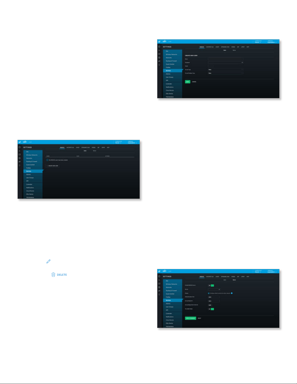
Chapter 3: Using the UniFi Controller Software
UniFi Controller User Guide
• Multicast Select this option to control unicast
traffic destined to unknown MAC addresses. Enter
the threshold in packets per second.
• Broadcast Select this option to monitor broadcast
traffic. Enter the threshold in packets per second.
- LLDP-MED You can use LLDP-MED (Link Layer
Discovery Protocol-Media Endpoint Discovery) for
device discovery and configuration of IP phones.
• Enable LLDP-MED Enabled by default.
• Enable topology change notification Disabled
by default. This allows the Switch to receive
notifications about any IP phone topology changes.
• Save Click to apply changes.
• Cancel Click to discard changes.
Settings > Services
You can configure a variety of services: RADIUS, Hotspot
2.0, DHCP, Dynamic DNS, MDNS, SIP, UPnP, and NTP.
RADIUS
Add RADIUS users and configure a RADIUS server.
Users
A list of RADIUS users is displayed.
Name Displays the name of the user.
VLAN Displays the assigned VLAN.
Actions Click a button to perform the desired action:
• Edit Click
Edit a User section.
• Delete Click
• Create New User Click to add a new user.
EDIT
to make changes. Go to the Create or
to delete the profile.
Create or Edit a User
Create a new user or make changes.
• Name Enter the name of the user.
• Password Enter a password.
• VLAN Enter the appropriate VLAN number.
• Tunnel Type Select the appropriate type: 1-Point-to-
Point Tunneling Protocol (PPTP), 2-Layer Two Forwarding
(L2F), 3-Layer Two Tunneling Protocol (L2TP), 4-Ascent
Tunnel Management Protocol (ATMP), 5-Virtual Tunneling
Protocol (VTP), 6-IP Authentication Header in the Tunnel-
mode (AH), 7-IP-in-IP Encapsulation (IP-IP), 8-Minimal
IP‑in‑IP Encapsulation (MIN‑IP‑IP), 9-IP Encapsulating
Security Payload in the Tunnel‑mode (ESP), 10-Generic
Route Encapsulation (GRE), 11-Bay Dial Virtual Services
(DVS), 12-IP-in-IP Tunneling, or 13-Virtual LANs (VLAN).
• Tunnel Medium Type Select the appropriate tunnel
medium type: 1-IPv4 (IP version 4), 2-IPv6 (IP version6),
3-NSAP, 4-HDLC (8-bit multidrop), 5-BBN 1822, 6-802
(includes all 802 media plus Ethernet “canonical format”),
7-E.163 (POTS), 8-E.164 (SMDS, Frame Relay, ATM),
9-F.69 (Telex), 10-X.121 (X.25, Frame Relay), 11-IPX,
12-AppleTalk, 13-Decnet IV, 14-Banyan Vines, or
15-E.164 with NSAP format subaddress.
• Save Click to apply changes.
• Cancel Click to discard changes.
Server
Configure a RADIUS server.
48
Enable RADIUS Server Click to configure a RADIUS
server.
Secret Enter the key shared with the RADIUS server.
Clients Clients are configured for the entire network.
Ubiquiti Networks, Inc.
Page 55
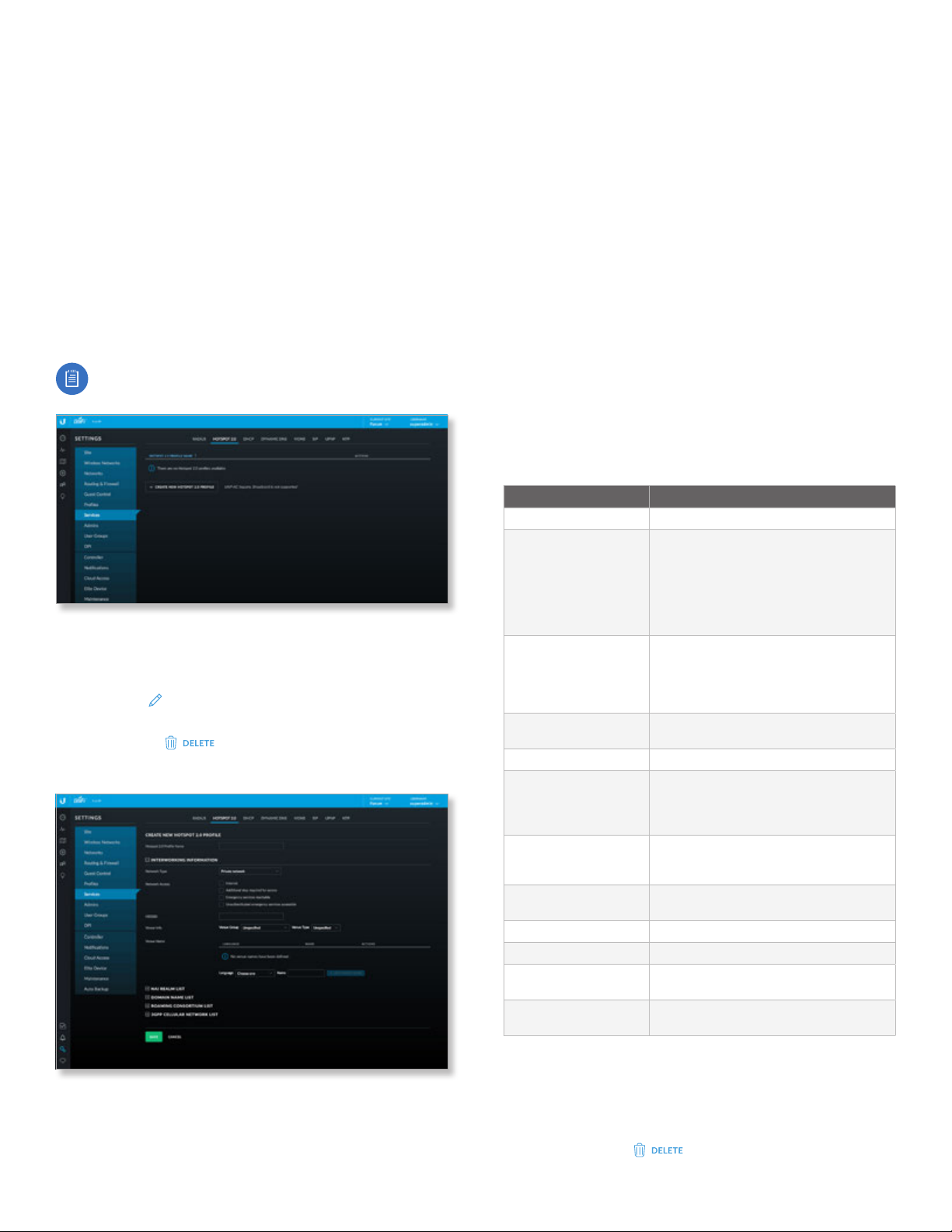
UniFi Controller User Guide
Chapter 3: Using the UniFi Controller Software
Authentication Port Enter the appropriate port number
to use for authentication; the default is 1812.
Accounting Port Enter the appropriate port number to
use for accounting; the default is 1813.
Accounting Interim Interval Enter the appropriate
duration between updates; the default is 3600 seconds.
Tunnelled Reply Enabled by default.
Apply Changes Click to save changes.
Reset Click to cancel changes.
Hotspot 2.0
Use this option to create Hotspot 2.0 profiles for each site.
Hotspot 2.0 is a standard for Wi-Fi roaming between Wi-Fi
and cellular networks with automatic authentication.
Note: The Hotspot 2.0 feature is supported by
generation 2 and 3 APs.
Hotspot 2.0 Profile Name Displays the name of the
Hotspot 2.0 profile.
Actions Click a button to perform the desired action:
• Edit Click
the Create or Edit a Hotspot 2.0 Profile section.
• Delete Click
Create or Edit a Hotspot 2.0 Profile
EDIT
to make changes to the profile. Go to
to delete the profile.
Internetworking Information
• Network Type Select the network type: Private
network, Private network with guest access,
Chargeable public network, Free public network,
Personal device network, Emergency services only
network, Test or experimental, or Wildcard.
• Network Access Configure these settings as required:
- Internet Disabled by default.
- Additional step required for access Disabled by
default.
- Emergency services reachable Disabled by default.
- Unauthenticated emergency services
accessible Disabled by default.
• HESSID Specify the Homogeneous External Service Set
Identifier (HESSID). This should be the MAC address of
one of the APs in the network.
• Venue Info Specify the Venue Group and Venue Type.
The available venue types vary depending on which
venue group is selected, as shown in the following table:
Venue Group Available Venue Types
Unspecified Unspecified
Assembly Unspecified, Arena, Stadium,
Business Unspecified, Doctor or Dentist office,
Educational Unspecified, Primary school,
Factory or Industrial Unspecified, Factory
Institutional
Mercantile Unspecified, Retail store, Grocery market,
Residential Unspecified, Private residence,
Storage Unspecified
Utility and Miscellaneous Unspecified
Vehicular Unspecified, Automobile or Truck, Airplane,
Outdoor
Passenger terminal, Amphitheater,
Amusement Park, Place of worship,
Convention center, Library, Museum,
Restaurant, Theater, Bar, Coffee shop,
Zoo or Aquarium, Emergency coordination
center
Bank, Fire station, Police station,
Post office, Professional office,
Research and development facility,
Attorney office
Secondary school, University or College
Unspecified, Hospital, Long‑Term Care Facility
(e.g., nursing home, hospice, etc.),
Alcohol and Drug Rehabilitation Center,
Group home, Prison orJail
Automotive service station, Shopping mall,
Gas station
Hotel or Motel, Dormitory, Boarding house
Bus, Ferry, Ship or Boat, Train, Motor Bike
Unspecified, Muni‑mesh Network, City park,
Rest area, Traffic control, Bus stop, Kiosk
• Hotspot 2.0 Profile Name Enter a name for the
Hotspot 2.0 profile.
Ubiquiti Networks, Inc.
• Venue Name Displays a list of Hotspot 2.0 venues that
have been created for the site:
- Language Displays the language used by the venue.
- Name Displays the name of the venue.
- Actions Click
to delete the venue.
49
Page 56
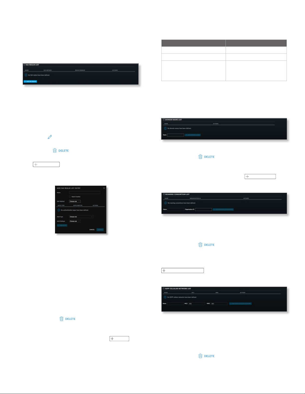
Chapter 3: Using the UniFi Controller Software
UniFi Controller User Guide
To add a venue name:
• Language Select the appropriate language.
• Name Enter a descriptive name.
• Add Venue Name Click to save the venue name.
NAI Realm List
• Name Displays the name of the NAI realm.
• EAP Method Displays the name of the EAP method that
is being used by the NAI realm.
• Realm Enabled Displays Yes if the realm is enabled or
No if the realm is not enabled.
• Actions Click a button to perform the desired action:
• Edit Click
EDIT
to make changes to the NAI realm.
Go to the Add or Edit a NAI Realm section.
• Delete Click
to delete the NAI realm.
• Add NAI Realm List To add an NAI realm to the list,
click
ADD NAI REALM
. Go to the Add or Edit a NAI Realm
section.
Add or Edit a NAI Realm
The available authentication subtypes vary depending on
the value of Auth Type, as shown in the following table:
Auth Type Auth Subtype
Non‑EAP Inner Authentication PAP, CHAP, MSCHAP, MSCHAPv2
Inner Authentication EAP Method None
Credential SM, USIM, NFC Secure Element,
Hardware Token, Softoken,
Certificate, Username/Password,
Anonymous, Vendor Specific
- Submit Click to save your changes to the NAI realm
list entry.
- Cancel Click to discard changes.
Domain Name List
• Name Displays the domain name.
• Actions Click
to delete the domain name
from the list.
• Add Domain Name To add a domain name to the list,
fill out the Name field, and then click
ADD DOMAIN NAME
.
Roaming Consortium List
- Name Enter the name of the NAI realm.
- Realm Enabled Check the box to enable the NAI
realm. This option is disabled by default.
- EAP Method Select the Extensible Authentication
Profile (EAP) method: EAP-TLS, EAP-SIM, EAP-TTLS,
EAP-AKA, or EAP-AKA’.
- (List of authentication types) Displays a list of
authentication types that have been defined for this
NAI realm list entry:
- Auth Type Displays the authentication type.
- Auth Subtype Displays the authentication subtype.
- Actions Click
to delete the authentication
type from the list.
To add an authentication type to the list, select the
AuthType and Auth Subtype, and then click
ADD AUTH
• Name Displays the name of the roaming consortium.
• Organization ID Displays the roaming consortium’s
IEEE-assigned organization ID.
• Actions Click
to delete the roaming
consortium from the list.
To add a roaming consortium to the list, fill out the
Name and Organization ID fields, and then click
ADD ROAMING CONSORTIUM
.
3GPP Cellular Network List
• Name Displays the name of the 3GPP cellular network.
• MCC Displays the Mobile Country Code (MCC). The
default is 001.
.
• MNC Displays the Mobile Network Code (MNC). The
default is 001.
• Actions Click
to delete the 3GPP cellular
network from the list.
50
Ubiquiti Networks, Inc.
Page 57
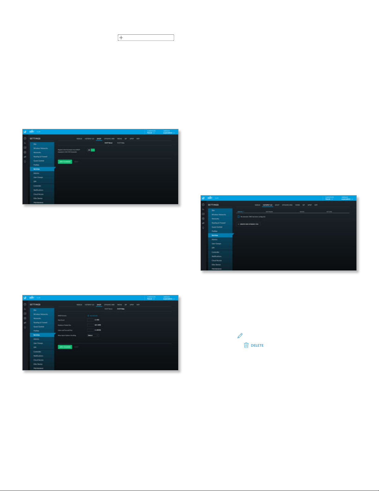
UniFi Controller User Guide
Chapter 3: Using the UniFi Controller Software
To add a 3GPP cellular network to the list, fill out the Name,
MCC, and MNC fields, and then click
ADD 3GPP CELLULAR NETWORK
.
Save Click to apply changes made to the profile.
Cancel Click to discard changes.
DHCP
A DHCP (Dynamic Host Configuration Protocol) server
assigns IP addresses to DHCP clients. You can add DHCP
servers and configure DHCP relay.
DHCP Server
The UniFi Security Gateway forwards DNS queries from
local clients to DNS servers.
Relay Agent Options Handling Specify what action
should be taken if the DHCP request already includes relay
information:
• Default Discards the DHCP packet.
• Append Adds to the existing DHCP packet.
• Discard Drops the DHCP packet.
• Forward Forwards the DHCP packet unchanged.
• Replace Replaces the existing DHCP packet.
Apply Changes Click to save changes.
Reset Click to cancel changes.
Dynamic DNS
Domain Name System (DNS) translates domain names
to IP addresses. Each DNS server on the internet holds
these mappings in its respective DNS database. Dynamic
Domain Name System (DDNS) is a network service that
notifies the DNS server in real time of any changes in the
device’s IP settings. Even if the device’s IP address changes,
you can still access the device through its domain name.
The list of DDNS entries is displayed:
Register client hostname from DHCP requests in USG
DNS forwarder Enabled by default.
Apply Changes Click to save changes.
Reset Click to cancel changes.
DHCP Relay
You can add additional DHCP servers and configure DHCP
relay settings. DHCP relay forwards DHCP packets to a
DHCP server when DHCP clients are not on the same local
network or subnet as their DHCP server.
DHCP Servers Click Add Server. Then enter the IP
address of the new DHCP server in the field provided.
Hop Count Enter the maximum number of hops allowed
(range: 1-255).
Maximum Packet Size Enter the maximum number of
packets allowed (range: 64-1400).
Listen and Transmit Port Enter the port number (range:
1-65535).
Service Displays the name of the DDNS service.
Hostname Displays the hostname registered with the
DDNS service.
Server Displays the IP address or hostname of the DDNS
server that should receive DDNS updates.
Actions Click a button to perform the desired action:
• Edit Click
• Delete Click
EDIT
to make changes.
to delete a DDNS entry.
Create New Dynamic DNS Click to create a DDNS entry.
Ubiquiti Networks, Inc.
51
Page 58
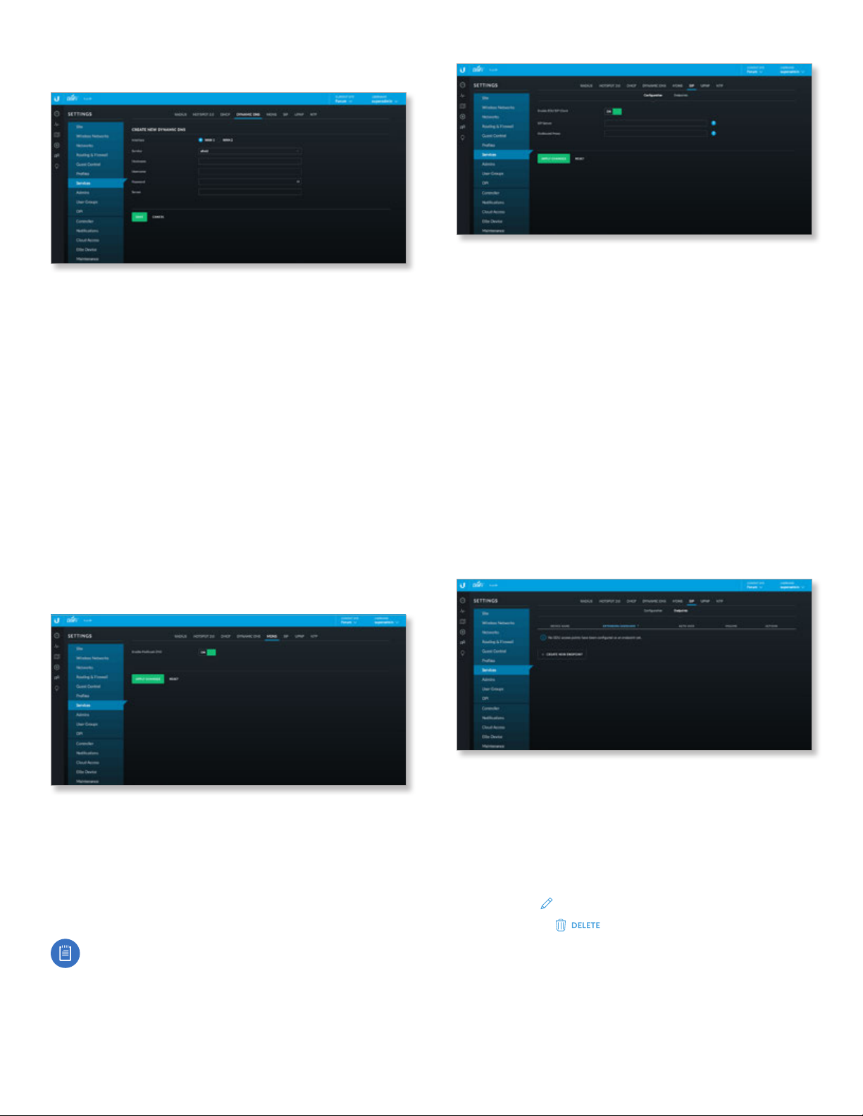
Chapter 3: Using the UniFi Controller Software
Create New Dynamic DNS
• Interface Select the appropriate interface, WAN 1 or
WAN 2.
• Service Select the appropriate DDNS service: afraid,
dnspark, dslreports, dyndns, easydns, namecheap,
sitelutions, or zoneedit.
• Hostname Enter the host name of the device.
• Username Enter the user name of the DDNS account.
• Password Enter the password of the DDNS account.
• Server Enter the address of your DDNS server.
• Save Click to apply changes.
• Cancel Click to discard changes.
MDNS
mDNS (Multicast DNS) creates an identifier for a device
to use as a hostname with a multicast service on a local
network. This helps simplify network configuration
because no unicast DNS server is needed.
UniFi Controller User Guide
Configuration
Primary SIP settings are configured. Use the Endpoint tab
to add each UAP-AC-EDU as an endpoint (SIP client).
Enable EDU SIP Client Click to use the UAP-AC-EDU as a
SIP client.
SIP Server For your SIP server, enter the IP address, IP
address with port number (IP:port), FQDN, or FQDN with
port number (FQDN:port). The default port is 5060.
Outbound Proxy Optional: For your outbound proxy
server, enter the IP address, IP address with port number
(IP:port), FQDN, or FQDN with port number (FQDN:port).
Apply Changes Click to save changes.
Reset Click to cancel changes.
Endpoint
Add each UAP-AC-EDU as an endpoint. The list of existing
endpoints is displayed.
Enable Multicast DNS Click to enable this option.
Apply Changes Click to save changes.
Reset Click to cancel changes.
SIP
You can configure the UAP-AC-EDU as a SIP client to use it
as an extension of a SIP phone system.
Note: The UAP-AC-EDU can be used either as part
of a SIP system or through the EDU app – not both.
For example, if the UAP-AC-EDU is configured as a
SIP client, then you cannot use the EDU app to make
broadcasts through it.
52
Device Name Displays the MAC address or hostname.
Extension/Username Displays the extension number or
username.
Auth User Displays the name of the authorized user.
Volume Displays the volume level.
Actions Click a button to perform the desired action:
• Edit Click
• Delete Click
EDIT
to make changes.
to delete an endpoint.
Create New Endpoint Click to add a UAP-AC-EDU as an
endpoint.
Ubiquiti Networks, Inc.
Page 59
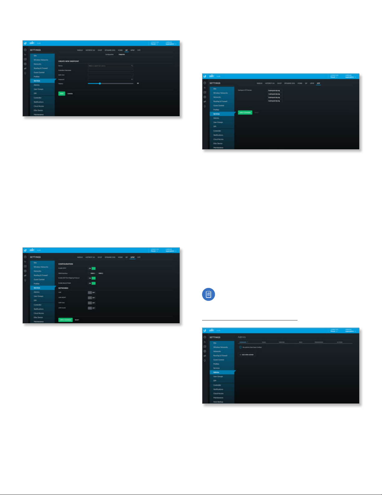
UniFi Controller User Guide
Chapter 3: Using the UniFi Controller Software
Create or Edit an Endpoint
• Device Select or search for the appropriate
UAP-AC-EDU.
• Extension/Username Enter the extension number or
username.
• Auth User Enter the name of the authorized user.
• Password Enter the SIP password.
• Volume Specify the volume level.
• Save Click to apply changes.
• Cancel Click to discard changes.
UPnP
Instead of manually configuring port forwarding rules, you
can use UPnP for automatic port forwarding when you
have hardware that supports UPnP.
NTP
NTP (Network Time Protocol) is a protocol for
synchronizing the clocks of computer systems over
packet-switched, variable-latency data networks. UniFi can
obtain the system time from NTP servers on the internet.
Configure NTP Servers The default server IP addresses
are displayed. You can designate different NTP servers.
Apply Changes Click to save changes.
Reset Click to discard changes.
Settings > Admins
You can create administrator accounts that are
site-specific; these site administrators can only see the
sites they manage and cannot see any devices that are
Pending Approval.
The superadmin account is created during the Setup
Wizard and has global admin (read/write) access; this
superadmin account cannot be revoked or re-invited.
Only the superadmin and admins who have permission to
adopt devices can view devices that are Pending Approval
and then adopt them on the UniFi Controller.
Configuration
Enable UPnP Disabled by default. Click to use this option;
additional settings will appear.
WAN Interface Select the appropriate interface, WAN 1
or WAN 2.
Enable NAT Port Mapping Protocol Enabled by default.
This protocol is typically used by Apple devices.
Enable Secure Mode Enabled by default. This restricts
port mappings to the clients’ own IP addresses.
Networks
LAN Click to use UPnP for your primary local network.
LAN__ Click to use UPnP for your local networks.
Apply Changes Click to save changes.
Reset Click to cancel changes.
Note: Ensure that you save the superadmin login
information for futureuse.
To create operator accounts for the Hotspot Manager, see
“Operator Accounts” on page 155
Username Displays the name of the administrator.
Email Displays the email address of the administrator.
Verified Displays a checkmark to indicate that an admin
is verified after he or she responds to an email invitation.
Role Displays the permissions level: Admin (read/write
access) or Read Only.
.
Ubiquiti Networks, Inc.
53
Page 60
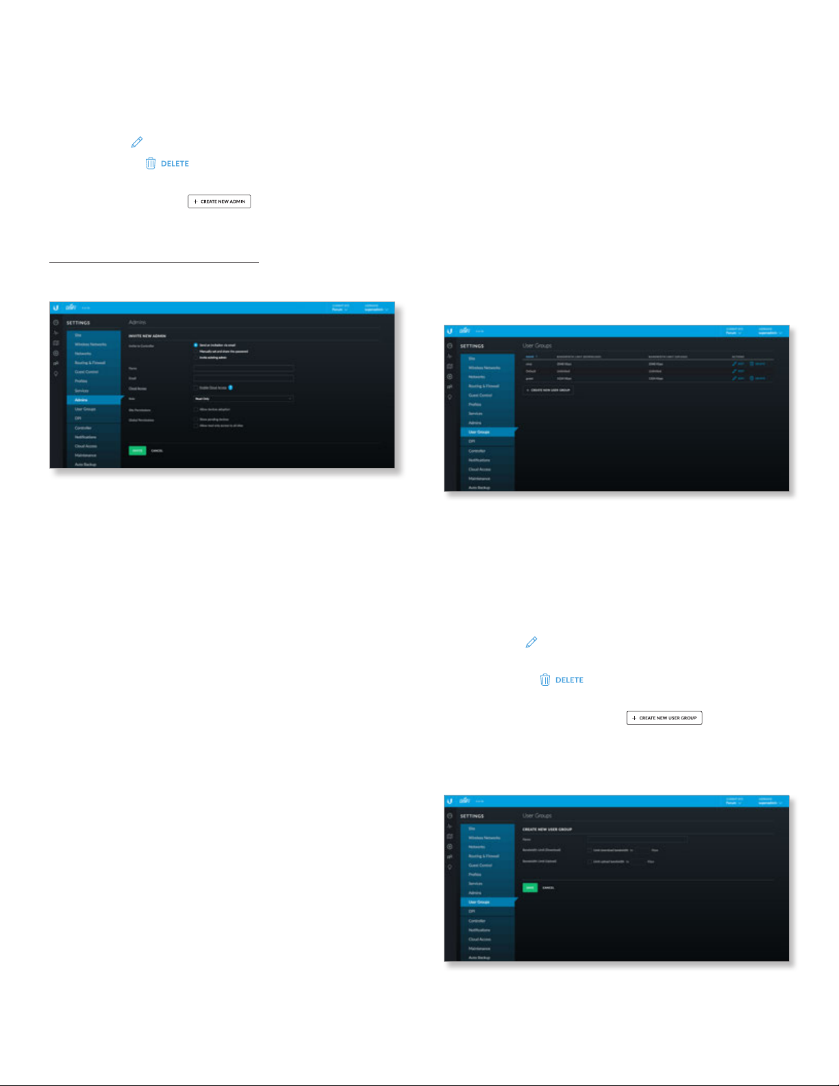
Chapter 3: Using the UniFi Controller Software
UniFi Controller User Guide
Permissions Displays whether the admin can adopt
devices, see pending devices, and/or have read-only
access to all sites.
Actions Click a button to perform the desired action:
• Edit Click
• Delete Click
EDIT
to make changes.
to delete the user group. (The
Default user group cannot be deleted.)
Add New Admin Click
to add a new admin. Go
to the Create or Edit an Admin section.
To create operator accounts for the Hotspot Manager, see
“Operator Accounts” on page 155.
Create or Edit an Admin
• Site Permissions Select this option to allow the new
administrator to adopt pending devices.
• Global Permissions There are two options:
- Show pending devices Select this option to allow
the new administrator to view pending devices.
- Allow read only access to all sites Select this option
to restrict the new administrator to read-only access
for all sites.
• Invite Click to invite the new administrator.
• Cancel Click to discard changes.
Settings > User Groups
Configure user groups on this screen. The default user
group is named Default and has no bandwidth limits.
• Invite to Controller Select this option to allow the
new administrator access. The admin who issued the
invitation can select which role the new administrator
will have with respect to the UniFi Controller. You have
three options:
- Send an invitation via email Send an email to the
new administrator.
• Name Enter the name of the new administrator.
• Email Enter the email address of the new
administrator.
• Cloud Access For remote access, select this option.
The new administrator must use his or her own
cloud account (linked to the same email address) to
manage the UniFi Controller.
- Manually set and share the password Set up the
password and share it with the new administrator.
• Name Enter the name of the new administrator.
• Password Enter the password for the new
administrator. Select Require the user to change
their password if you want the password changed
after the initial login.
• Email Enter the email address of the new
administrator.
- Invite existing admin Add an administrator from
another site.
• Select Admin Search for an existing administrator
from the drop-down list.
• Role Select Administrator (read/write access) or
ReadOnly.
User Group Settings
Name Displays the name of the user group.
Bandwidth Limit (Download) Displays the download
limit.
Bandwidth Limit (Upload) Displays the upload limit.
Actions Click a button to perform the desired action:
• Edit Click
settings. Go to the Create or Edit a User Group section.
• Delete Click
Default user group cannot be deleted.)
Create New User Group Click
a new user group. Go to the Create or Edit a User Group
section.
Create or Edit a User Group
• Name Enter or edit the name of the user group.
EDIT
to make changes to the user group
to delete the user group. (The
to create
54
Ubiquiti Networks, Inc.
Page 61

UniFi Controller User Guide
Chapter 3: Using the UniFi Controller Software
• Bandwidth Limit (Download) Select to limit the
download bandwidth. Enter the maximum in Kbps.
• Bandwidth Limit (Upload) Select to limit the upload
bandwidth. Enter the maximum in Kbps.
• Save Click to apply changes.
• Cancel Click to discard changes.
See “Wireless Client – Configuration” on page 148
or “Wired Client – Configuration” on page 150
for information on how to assign a user or guest to a
usergroup.
Settings > DPI
Configure the Deep Packet Inspection (DPI) settings of the
UniFi Controller.
Enable DPI When enabled, this option turns on the
DPI feature of the UniFi Security Gateway. The data will
accumulate until you either click Clear DPI Counters
(described below) or reboot/upgrade the Gateway. This
feature will not work for any WAN connection when Smart
Queue is enabled on it.
Clear DPI Counters Click this button to clear the DPI
counters.
Apply Changes Click to save changes.
Reset Click to cancel changes.
DPI Restriction Groups
Add Group Click
Add Group section.
One group is created by default. Click + to expand the
section for any group.
The following information is listed for each restriction:
Category/App Displays the traffic category or
application.
Enabled Displays the status of the restriction.
Blocked Displays whether matching traffic is blocked.
Log Traffic Displays whether matching traffic is logged.
Actions Click the appropriate button:
• Edit Click
• Delete Click
group. (The Default group cannot be deleted.)
Add Restriction Click
the Add Restriction section.
EDIT
to make changes.
to add a group. Go to the
to delete the DPI restriction
to add a restriction. Go to
Add Group
• Group Name Enter a descriptive name.
• Create Click to apply changes.
• Cancel Click to discard changes.
Add Restriction
• Select Category Select the appropriate traffic category
from the drop-down list, and then click .
• Enabled Select to apply this restriction to the selected
group.
• Block Select to block all traffic that matches this
restriction.
• Log Traffic Select to log all traffic that matches this
restriction.
• Save Click to apply changes.
• Cancel Click to discard changes.
DPI Restriction Assignments
Click to expand the section for networks.
The following information is listed for each wired network:
Network Displays the name of the network.
Group Name Displays the name of the DPI restriction
group.
Purpose Displays the purpose of the restriction.
Subnet Displays the subnet mask.
Ubiquiti Networks, Inc.
55
Page 62
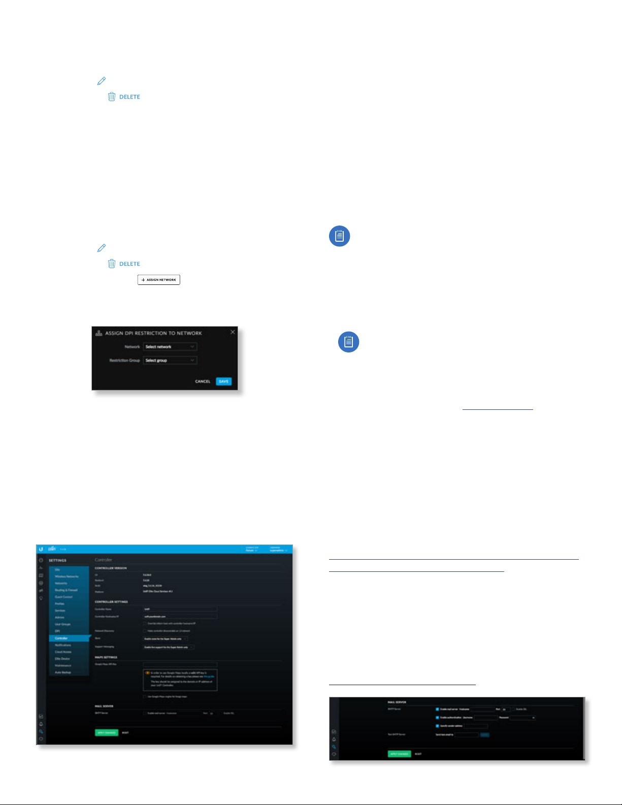
Chapter 3: Using the UniFi Controller Software
UniFi Controller User Guide
VLAN Displays the assigned VLANs, if any.
Actions Click the appropriate button:
• Edit Click
• Delete Click
EDIT
to make changes.
to delete the restriction.
The following information is listed for each wireless
network:
Network Displays the name of the network.
Group Name Displays the name of the DPI restriction
group.
Security Displays the security description.
Guest Network Displays the name of the guest network.
VLAN Displays the assigned VLANs, if any.
Actions Click the appropriate button:
• Edit Click
• Delete Click
Assign Network Click
EDIT
to make changes.
to remove this assignment.
to assign a restriction. Go
to the Assign Restriction section.
Assign Restriction
• Network Select the appropriate wired or wireless
network from the drop-down list.
• Restriction Group Select the appropriate DPI
restriction group from the drop-down list.
• Save Click to apply changes.
• Cancel Click to discard changes.
Settings > Controller
(Available for the superadmin only.) Configure the system
settings of the UniFi Controller.
Controller Version
UI Displays the version number of the user interface.
Backend Displays the version number of the server-side
application and database.
Build Displays the version number of the software build.
Platform Displays the version number of the cloud
service.
Controller Settings
Controller Name Enter a descriptive name for your UniFi
Controller instance.
Controller Hostname/IP (For advanced users only.) Enter
the hostname or IP address of the UniFi Controller.
Note: When alert emails are sent out, the Controller
Hostname/IP will be specified in the Controller URL at
the bottom of every message.
• Override inform host with controller hostname/IP An
inform host URL is used for Layer-3 device adoption
using the UniFi Discovery Utility. Select this option
to override the inform host URL. Then enter the
appropriate hostname or IP address.
Note: The default inform port is 8080. (You can
customize this in system.properties.)
Network Discovery When enabled, this option allows
UniFi to be discoverable via UPnP on the Layer-2 network.
This option is disabled by default.
Store Users can have a link to store.ubnt.com. Select the
appropriate option: Enable store for the Super Admin
only, Enable store for all users, or Disable store for all
users.
Support Messaging Select the appropriate option:
Enable Live Chat for the Super Admin only, Enable Live
Chat for all users, or Disable Live Chat for all users.
Maps Setting
If you want to use Google Maps on the Map screen, you
need a Google API key. Follow the instructions in the
following article to obtain a Google API key:
https://developers.google.com/maps/documentation/
javascript/get-api-key#get-an-api-key
Google Maps API Key Enter a valid API key.
Use Google Maps engine for image maps Select this
option to enable the use of Google Maps.
Mail Server
When enabled, UniFi will send email alerts triggered by
disconnected UniFi devices. Specify the administrator
email address when you create an account under
“Settings > Admins” on page 53.
56
Ubiquiti Networks, Inc.
Page 63
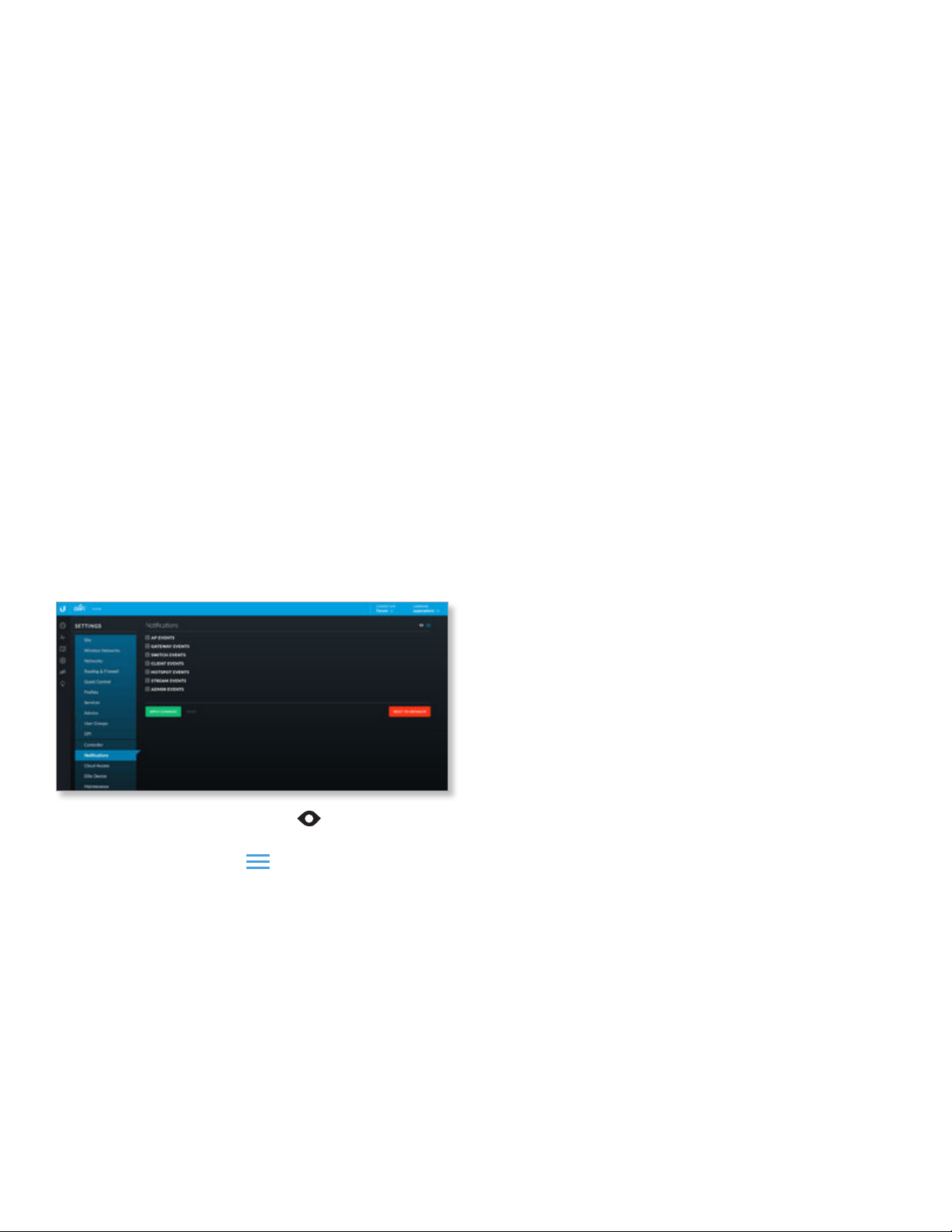
UniFi Controller User Guide
Chapter 3: Using the UniFi Controller Software
SMTP Server Select this option to enable emails.
• Hostname Enter the outgoing (SMTP) mail server
name.
• Port The default is 25. If Secure Sockets Layer (SSL)
is enabled, then the port number will automatically
change to 465.
• Enable SSL You can enable SSL to enhance secure
communications over the internet.
• Enable authentication Select this option to enable
authentication.
- Username Enter the username required by the
mailserver.
- Password Enter the password required by the
mailserver.
• Specify sender address Select this option to specify
the sender email address. Enter the email address that
will appear as the sender of the email alert.
• Test SMTP Server Enter an email address and click
Send to test the mail server setup.
Apply Changes Click to save changes.
Reset Click to cancel changes.
Settings > Notifications
Customize the types of notifications you receive from the
UniFi Controller for a variety of events.
(show/hide disabled events) Click to show or hide
disabled events on the Notifications screen.
(collapse/expand all) Click to collapse all events to
their section headings or expand to display all events on
the Notifications screen.
AP Events Click to access AP Events notifications.
Select the appropriate notification type for the following
event types involving APs: AP adopted, AP automatically
readopted, AP changed channel, AP configured, AP
connected, AP deleted, Rogue AP detected, Pending AP
discovered, AP elite license assigned, Elite AP offline, AP elite
license revoked, AP upgrade failed (firmware check), AP
upgrade failed (download), AP failed host key verification,
AP isolated, AP license changed, AP disconnected, AP
event, AP channel interference, AP detected radar, Pending
AP rediscovered, AP restarted by admin, AP restarted by
unknown, Rolling upgrade triggered, AP upgrade scheduled,
AP upgraded, AP wireless event, Wireless uplink configured,
and Wireless uplink disconnected.
• Event Select this option to receive a notification on the
Events screen.
• Alert Select this option to receive a notification on the
Alerts screen.
• Email Select this option to receive a notification email.
Gateway Events Click to access Gateway Events
notifications.
Select the appropriate notification type for the following
event types involving Gateways: Gateway adopted,
Gateway automatically readopted, Gateway commit error,
Gateway connected, Gateway deleted, Pending gateway
discovered, Gateway elite license assigned, Elite gateway
offline, Gateway elite license revoked, Gateway upgrade
failed (firmware check), Gateway upgrade failed (download),
Gateway failed host key verification, Gateway license
changed, Gateway disconnected, Gateway event, Gateway
restarted by admin, Gateway restarted by unknown,
Gateway upgrade scheduled, and Gateway upgraded.
Event Select this option to receive a notification on the
Events screen.
Alert Select this option to receive a notification on the
Alerts screen.
Email Select this option to receive a notification email.
Switch Events Click to access Switch Events notifications.
Select the appropriate notification type for the following
event types involving Switches: Switch adopted, Switch
automatically readopted, Switch connected, Switch
deleted, Switch detected rogue DHCP server, Pending
switch discovered, Switch elite license assigned, Elite switch
offline, Switch elite license revoked, Switch upgrade failed
(firmware check), Switch upgrade failed (download), Switch
failed host key verification, Switch license changed, Switch
loop detected, Switch disconnected, Switch event, Switch
overheating, Switch restarted by admin, Switch restarted by
unknown, Switch upgrade scheduled, and Switch upgraded.
• Event Select this option to receive a notification on the
Events screen.
• Alert Select this option to receive a notification on the
Alerts screen.
• Email Select this option to receive a notification email.
Client Events Click to access Client Events notifications.
Select the appropriate notification type for the following
event types involving clients: Client blocked (wired),
Client unblocked (wired), Guest connected (wired),
Guest disconnected (wired), User connected (wired),
User disconnected (wired), Client blocked (wireless),
Client unblocked (wireless), Guest unauthorized, Guest
unauthorized by quota, Guest connected (wireless), Guest
disconnected (wireless), Guest AP roaming, Guest channel
roaming, User connected (wireless), User disconnected
(wireless), User AP roaming, and User channel roaming.
Ubiquiti Networks, Inc.
57
Page 64
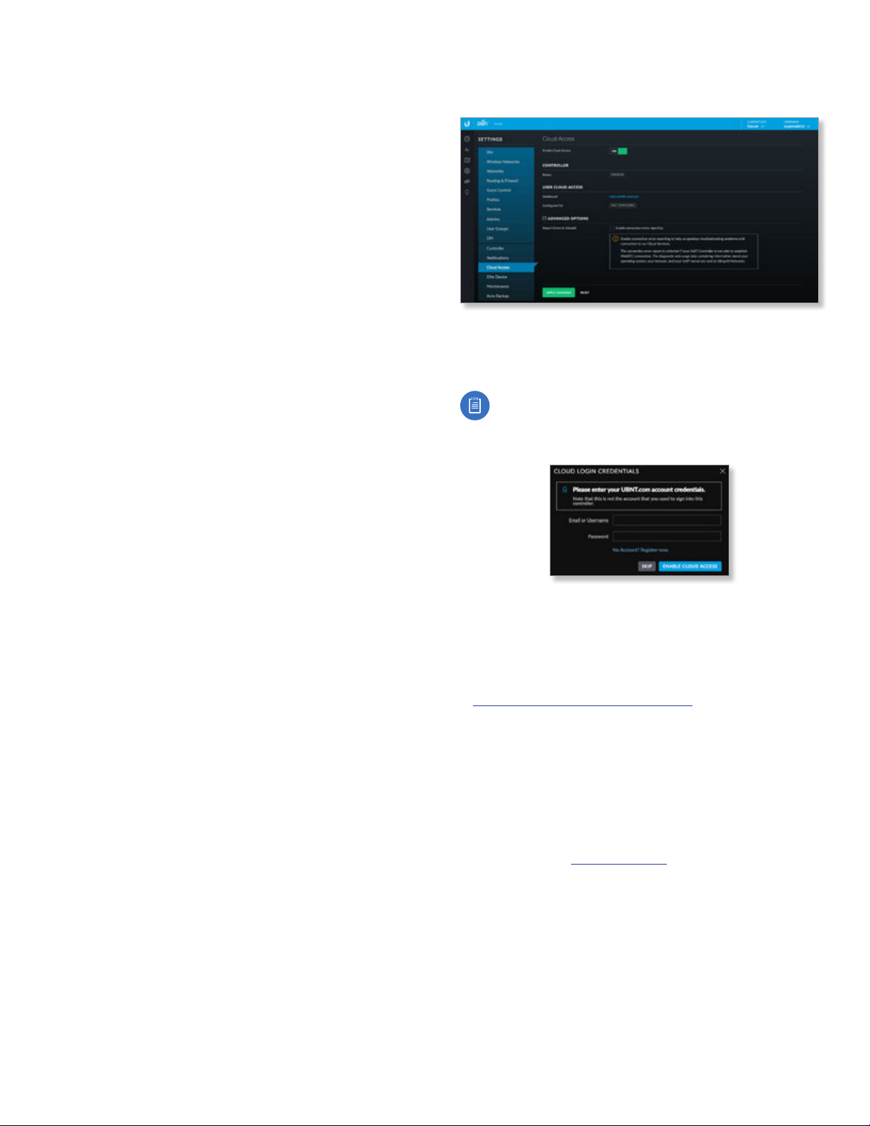
Chapter 3: Using the UniFi Controller Software
UniFi Controller User Guide
• Event Select this option to receive a notification on the
Events screen.
• Alert Select this option to receive a notification on the
Alerts screen.
• Email Select this option to receive a notification email.
Hotspot Events Click to access Hotspot Events
notifications.
Select the appropriate notification type for the following
event types involving hotspots: Guest authorized w/o
authentication, Guest authorized by password, Guest
payment processed, and Voucher used.
• Event Select this option to receive a notification on the
Events screen.
• Alert Select this option to receive a notification on the
Alerts screen.
• Email Select this option to receive a notification email.
Stream Events Click to access Stream Events notifications.
Select the appropriate notification type for the following
event types involving streaming: Stream config incorrect,
Scheduled stream failed, and Stream skipped devices.
• Event Select this option to receive a notification on the
Events screen.
• Alert Select this option to receive a notification on the
Alerts screen.
• Email Select this option to receive a notification email.
Admin Events Click to access Admin Events notifications.
Select the appropriate notification type for the following
event types involving administrators: Auto backup failed,
Guest authorized, Guest authorization extended, Guest
unauthorized, Hotspot operator login, Admin login, Admin
login failed, Payment refunded, Controller update available,
Voucher(s) created, and Voucher deleted.
• Event Select this option to receive a notification on the
Events screen.
• Alert Select this option to receive a notification on the
Alerts screen.
• Email Select this option to receive a notification email.
When you are done with customizing the notifications,
you have the following options:
Apply Changes Click to save changes.
Reset Click to cancel changes.
Reset to Defaults Click to reset to the factory default
settings.
Settings > Cloud Access
Set up the login for cloud access.
Cloud Access
Enable Cloud Access Disabled by default. Click to
configure the login.
Note: Enabling or disabling cloud access will affect
cloud access for all admins on that UniFi Controller.
The Cloud Login Credentials screen will appear.
• Email or Username Enter the email address or
username of your UBNT account.
• Password Enter the password of your UBNT account.
• No account? Register now. If you do not have a UBNT
account, click here to visit this link:
https://account.ubnt.com/register
Follow the on-screen instructions to set up an account.
• Enable Cloud Access Click to save changes.
• Skip Click to skip the login.
Controller
Status Displays “Connected” if cloud access is active.
User Cloud Access
Dashboard Click unifi.ubnt.com to access the dashboard
for your cloud account.
Configured for Displays the username or email address
of your UBNT account.
Advanced Options
Click to display the advanced option:
Report Errors to Ubiquiti Disabled by default. To enable
connection errors to be reported to Ubiquiti, select this
option. This allows us to acquire technical information to
help troubleshoot any issues with connecting to our cloud
services.
58
Ubiquiti Networks, Inc.
Page 65
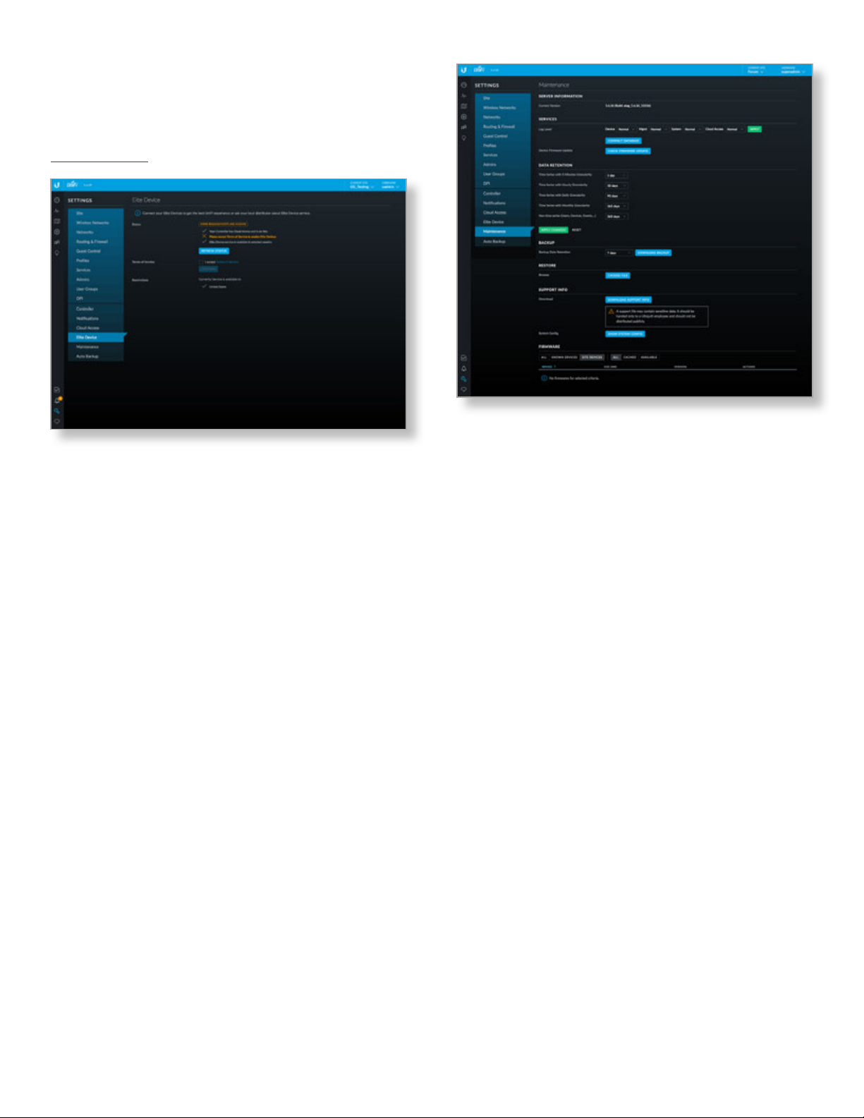
UniFi Controller User Guide
Apply Changes Click to save changes.
Reset Click to cancel changes.
Settings > Elite
For information about the UniFi Elite service, go to:
www.ubnt.com
Status
This section describes the status of the UniFi Elite service
requirements, which includes, cloud access, online
availability, acceptance of the Terms of Service, and Elite
service availability in the applicable country.
Refresh Status Click to update the status information.
Terms of Service
I accept Terms of Service You can click Terms of Service
to review the terms. To use the service, select I accept
Terms of Service.
Confirm Click to confirm acceptance of these terms.
Restrictions
UniFi Elite service is currently available in the countries
listed.
Settings > Maintenance
(Available for the superadmin only.) The Maintenance
screen contains administrative options, so you can
customize logs, manage system backups, and download
configuration information to assist in support issues.
If your UniFi Controller is running on a UniFi Cloud Key,
you can use the Maintenance tab to upgrade the UniFi
Cloud Key firmware, upgrade the UniFi Controller software
located on the UniFi Cloud Key, reboot the UniFi Cloud
Key, power it off, or reset it to factory defaults.
Chapter 3: Using the UniFi Controller Software
Server Information
Current Version Displays the software version.
Services
Log Level You can customize the support information
that is collected:
• Device Select the level of severity required to trigger
device log entries: Normal, More, or Debug. The default
is Normal.
• Mgmt Select the level of severity required to trigger
management log entries: Normal, More, or Debug. The
default is Normal.
• System Select the level of severity required to trigger
system log entries: Normal, More, or Debug. The
default is Normal.
• Cloud Access Select the level of severity required to
trigger system log entries: Normal, More, or Debug. The
default is Normal.
• Apply Click to save changes.
Compact Database Click to optimize disk usage by
freeing up pre-allocated disk space. There may be service
interruptions during the process. Click Confirm to
continue.
Device Firmware Update Click to check for available
firmware updates.
Data Retention
Time Series with 5 Minutes Granularity Select the
appropriate interval: 1 hour, 2 hours, 6 hours, 12 hours,
1day, 7 days, or 30 days. The default is 1day.
Time Series with Hourly Granularity Select the
appropriate interval: 1 day, 7 days, 30 days, 60days,
90days, 180 days, or No limit. The default is 30days.
Ubiquiti Networks, Inc.
59
Page 66
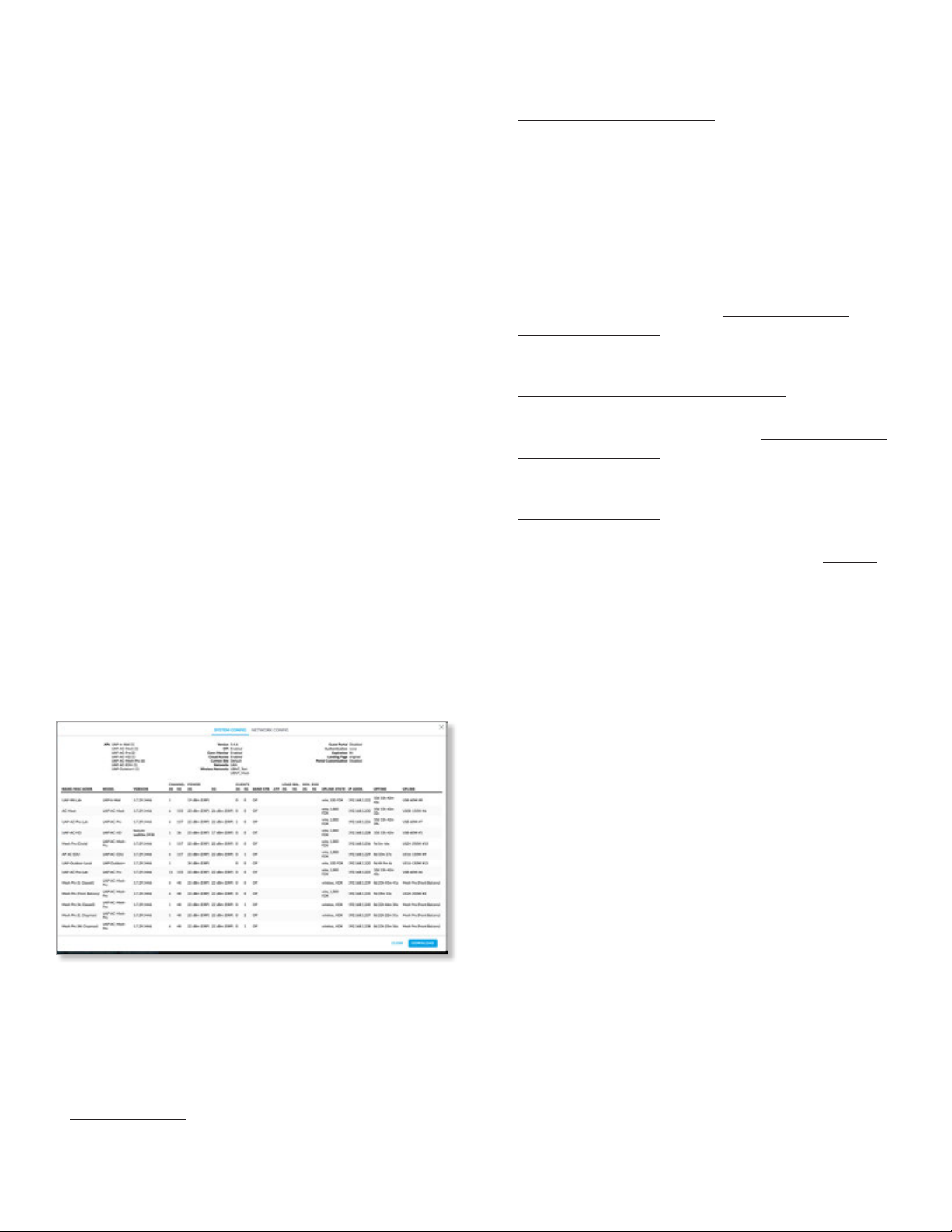
Chapter 3: Using the UniFi Controller Software
UniFi Controller User Guide
Time Series with Daily Granularity Select the
appropriate interval: 31 days, 90 days, 180 days,
365days, or No limit. The default is 90days.
Time Series with Monthly Granularity Select the
appropriate interval: 31 days, 90 days, 180 days,
365days, or No limit. The default is 365days.
Non time series (Users, Devices, Events...) Select the
appropriate interval: 7 days, 30 days, 60 days, 90 days,
180 days, 365days, or No limit. The default is 365days.
Apply Changes Click to save changes.
Reset Click to cancel changes.
Backup
Backup Data Retention Select the time duration of the
backup data retention: 7 days, 30 days, 60 days, 90 days,
180 days, 365days, or No limit. The default is 7days.
Download Backup Click this option to download a file
that contains all of your settings and data retained for the
duration you specify, so you can restore them later if you
choose.
Restore
Browse Click Choose File to select a backup file that
you’ve already downloaded. Follow the on-screen
instructions to restore settings from the selected file.
Support Info
Download Click Download Support Info to download
a file to your computer with information about your
configuration. You can email this file to our support team.
System Config Click Show System Config to view
configuration settings. The System Config screen appears.
System Config
• Network Config Click Network Config to view the
network configuration settings.
• APs Displays the APs by model and quantity.
• Version Displays the software version.
• DPI Displays the status of the DPI (Deep Packet
Inspection) feature, which is configured in “Settings >
Site” on page 21.
• Conn Monitor Displays the status of the Uplink
Connectivity Monitor feature, which is configured in
“Settings > Site” on page 21.
• Cloud Access Displays the status of the Cloud Access
feature.
• Current Site Displays the name of the current site.
• Networks Displays the name(s) of the current
network(s).
• Wireless Networks Displays the name(s) of the current
wireless networks.
• Guest Portal Displays the status of the Guest Portal
feature, which is configured in “Settings > Guest
Control” on page 37.
• Authentication Displays the type of authentication
required for guest access, which is configured in
“Settings > Guest Control” on page 37.
• Expiration Displays the period of time before a guest
login expires, which is configured in “Settings > Guest
Control” on page 37.
• Landing Page Displays the type of landing page for
guest access, which is configured in “Settings > Guest
Control” on page 37.
• Portal Customization Displays the status of the Portal
Customization feature, which is configured in “Portal
Customization” on page 40.
• Name/MAC Addr. Displays the hostname, alias, or MAC
address of the device.
• Model Displays the model number of the device.
• Version Displays the version number of the firmware.
• Channel 2G/5G Displays the channel used on each
radio band.
• Power 2G/5G Displays the TX power used on each
radio band.
• Clients 2G/5G Displays the number of clients on each
radio band.
• Band Str. Displays the status of the band steering
feature.
• ATF Displays the status of the airtime fairness feature.
• Load Bal. 2G/5G Displays the load balancing for the 2.4
and 5 GHz radio bands.
• Min. RSSI 2G/5G Displays the minimum client signal
threshold for each radio band.
• Uplink State Displays the status of the uplink, if
applicable.
• IP Addr. Displays the local IP address of the device.
• Uptime Displays the duration of time the device has
been running.
• Uplink Displays the duration of the uplink connection.
• Close Click Close to exit this screen.
• Download Click Download to download a screenshot
in .png format.
60
Ubiquiti Networks, Inc.
Page 67
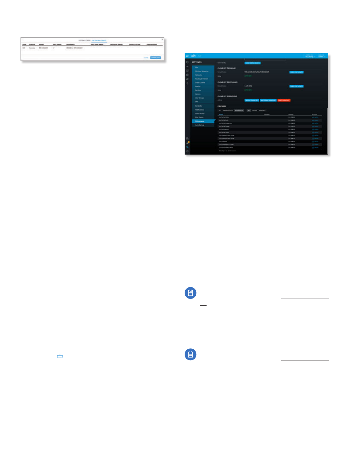
UniFi Controller User Guide
CACHE
Chapter 3: Using the UniFi Controller Software
Network Config
• Name Displays the name of the local wired network.
• Purpose Displays a description of this network.
• Subnet Displays the IP address and prefix size.
• DHCP Server Displays the status of the DHCP server
feature.
• DHCP Range Displays the range of available IP
addresses.
• DHCP Name Server Displays the IP address of the DNS
server.
• DHCP WINS Server Displays the IP address of the WINS
server.
• DHCP Lease Time Displays the lease time for any
assigned IP address.
• IGMP Snooping Displays the status of the IGMP
Snooping feature.
• Close Click Close to exit this screen.
• Download Click Download to download a screenshot
in .png format.
Cloud Key
If you have a Cloud Key, go to the following sections:
• Cloud Key Firmware
• Cloud Key Controller
• Cloud Key Operations
Firmware
The Firmware section displays firmware versions according
to the following filters:
(device) Select the appropriate filter: All, Known Devices,
or Site Devices.
(firmware version) Select the appropriate filter: All,
Cached, or Available.
Device Displays the device name.
Size (MB) Displays the size of the file.
Version Displays the firmware version number.
Actions Click a button to perform the desired action.
• Cache Click
local hosting. This can be used for batch upgrades to
groups of devices.
to save the firmware version for
Cloud Key Firmware
The Cloud Key Firmware section is available if you are using
a UniFi Cloud Key.
Current Version Displays the version number of the UniFi
Cloud Key firmware. Click Check for Update to see if there
is a newer firmware version. If there is, then you can follow
the on-screen instructions to upgrade now.
Available Update If there is an available update, then
the available firmware version number is displayed. Click
Apply Update to upgrade the firmware.
Status Displays the current status, Up to Date or Update
Available.
Cloud Key Controller
The Cloud Key Controller section is available if you are
using a UniFi Cloud Key.
Current Version Displays the version number of the UniFi
Controller software. Click Check for Update to see if there
is a newer software version. If there is, then you can follow
the on-screen instructions to upgrade now.
Note: We recommend that you back up your UniFi
Controller configuration (refer to “Backup” on page
60 for more information) before upgrading.
Available Update If there is an available update, then
the available software version number is displayed. Click
Apply Update to upgrade the software.
Status Displays the current status, Up to Date or Update
Available.
Note: We recommend that you back up your UniFi
Controller configuration (refer to “Backup” on page
60 for more information) before upgrading.
Cloud Key Operations
Restart Cloud Key Click this option to powercycle the
UniFi Cloud Key.
Shut Down Cloud Key Click this option to turn off the
UniFi Cloud Key.
Ubiquiti Networks, Inc.
61
Page 68
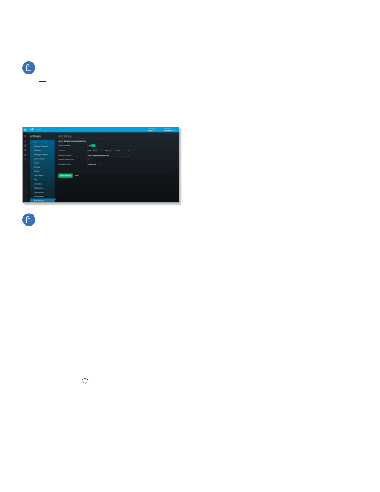
Chapter 3: Using the UniFi Controller Software
Reset Cloud Key Click this option to reset the UniFi Cloud
Key to its factory default settings. This option will reboot
the UniFi Cloud Key, and all factory default settings will be
restored.
Note: We recommend that you back up your UniFi
Controller configuration (refer to “Backup” on page
60 for more information) before resetting the
UniFi Cloud Key to its defaults.
Settings > Auto Backup
Configure the automatic backup settings for the UniFi
Controller.
UniFi Controller User Guide
Note: If you are using a UniFi Cloud Key, make sure
to insert an SD memory card before enabling this
feature.
Enable Auto Backup Enable this option to turn on the
automatic backup feature. Then configure the options:
• Occurrence Select how often to perform auto backup:
(every) Hour, Day, Week, Month, or Year. Then select the
appropriate time, day, and/or month, if applicable.
• Occurrence Timezone Select your time zone.
• Maximum Number of Files Specify the maximum
number of backup files to save. The default is 7.
• Data Retention Days Specify the length of time in
days that data will be retained: Settings only, 7 days,
30days, 60 days, 90 days, 180 days, 365 days, or
Nolimit.
Apply Changes Click to save changes.
Reset Click to cancel changes.
Chat with Us
(Available if you are a superadmin or you are allowed to
access live chat.) Click to open a window for online chat
support.
62
Ubiquiti Networks, Inc.
Page 69
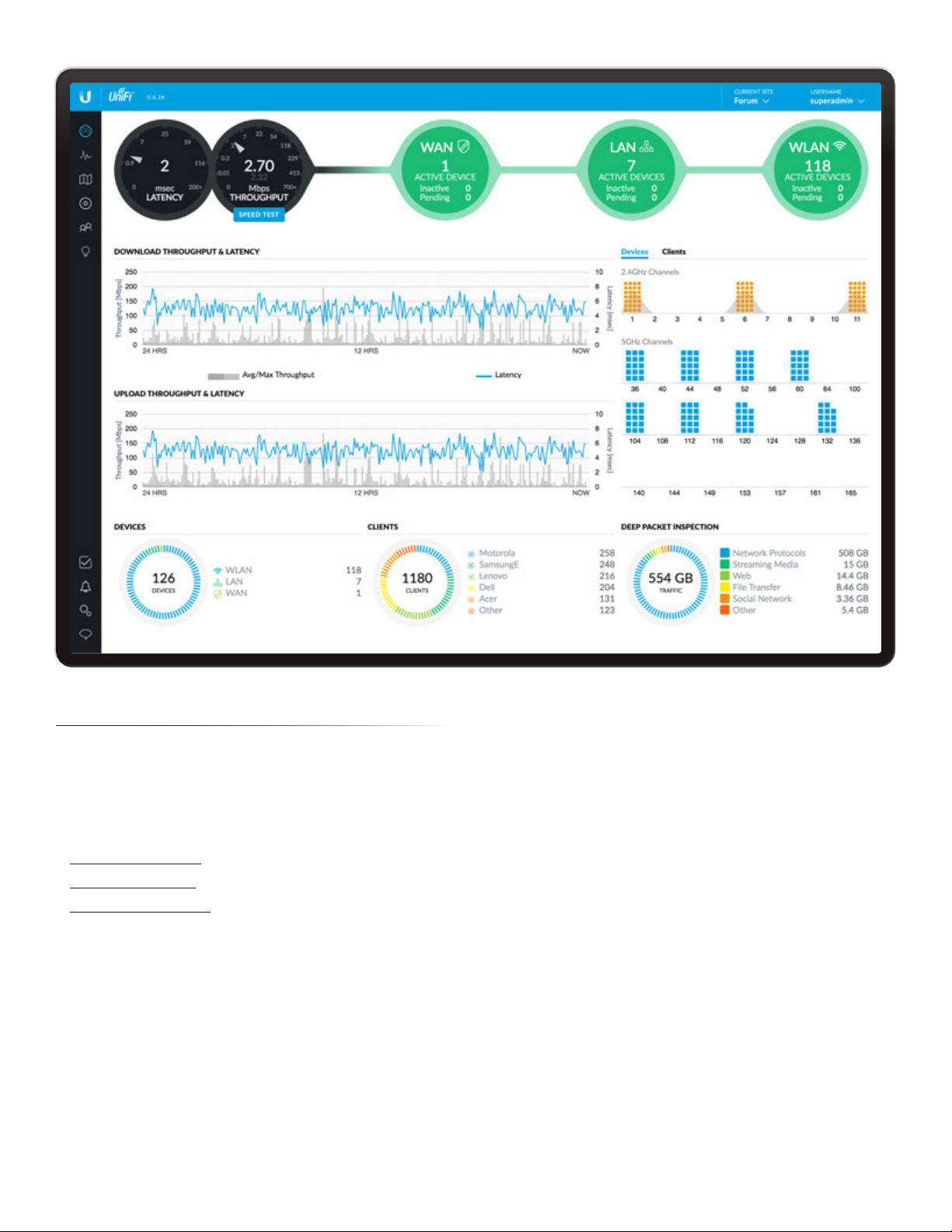
UniFi Controller User Guide
Chapter 4: Dashboard
Chapter 4: Dashboard
The Dashboard screen provides a visual representation of
your network’s status. Basic information is provided for
each node:
• Latency
• Throughput
• “WAN” on page 64
• “LAN” on page 64
• “WLAN” on page 65
Latency
The latency value from the latest Speed Test is displayed.
The monitor is color-coded to indicate status:
Black A UniFi Security Gateway is active, and the Speed
Test is available.
Red The Speed Test is not available because it requires an
active UniFi Security Gateway.
Throughput
The throughput value from the latest Speed Test is
displayed. The monitor is color-coded to indicate status:
Black A UniFi Security Gateway is active, and the Speed
Test is available.
Red The Speed Test is not available because it requires an
active UniFi Security Gateway.
Status information Click the Latency or Throughput
monitor to display the following:
WWW
Current status information is displayed.
• Uptime Displays the length of time the internet
connection has been active.
• Latency Displays the amount of time it takes a packet
to travel from the UniFi Security Gateway to the service
provider’s gateway.
• Up Displays the upload rate of your internet
connection.
• Down Displays the download rate of your internet
connection.
Speed Test
Results from the latest Speed Test are displayed.
• Last Run Displays the duration of time since the last
Speed Test.
Ubiquiti Networks, Inc.
63
Page 70
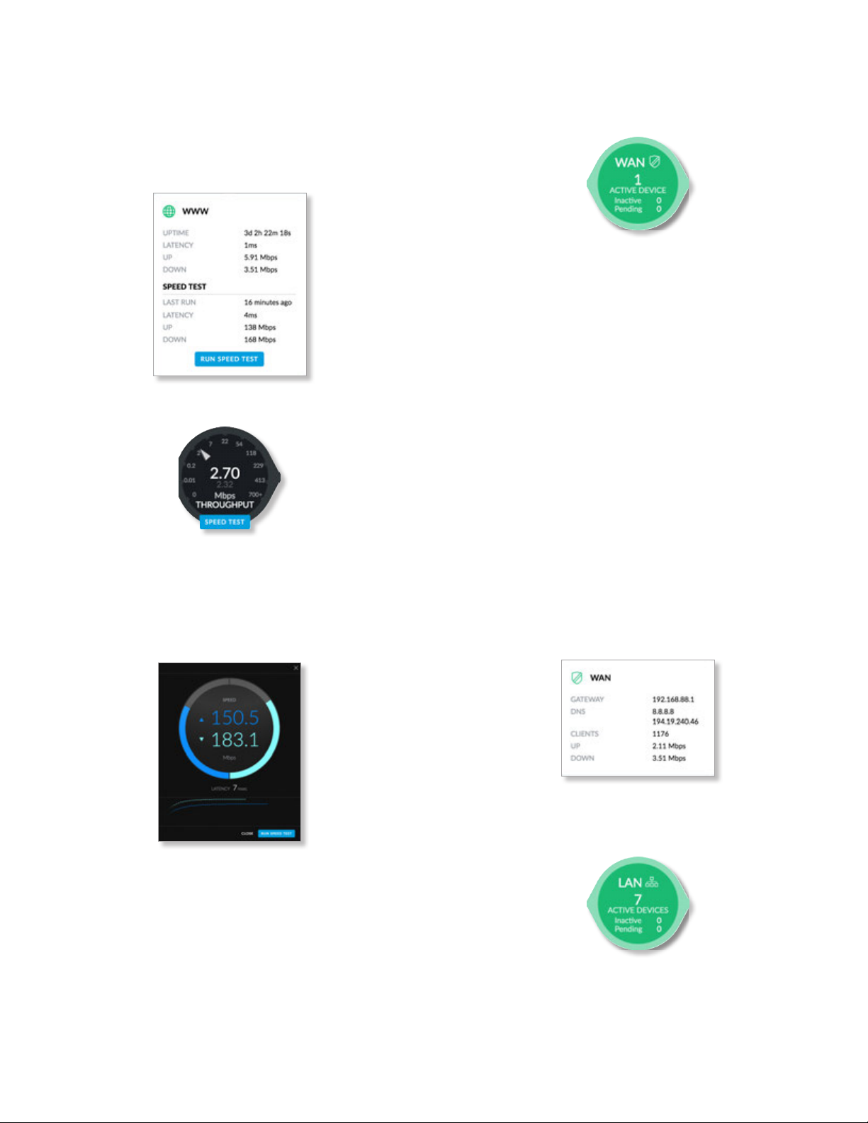
Chapter 4: Dashboard
UniFi Controller User Guide
• Latency Displays the amount of time it takes a packet
to travel from the UniFi Security Gateway to the service
provider’s gateway.
• Up Displays the upload speed.
• Down Displays the download speed.
• Run Speed Test Click to run the Speed Test.
Speed Test Click to run the Speed Test.
After the Speed Test is complete, the following will be
displayed:
• Download speed
• Upload speed
• Latency, duration of the average Ping round-trip time
WAN
The basic details of the UniFi Security Gateway are
displayed.
The monitor is color-coded to indicate status:
Green The WAN connection is active.
Red The WAN connection is inactive.
Active Devices Displays the number of Gateway devices
adopted and active.
Inactive Displays the number of Gateway devices
adopted but not active.
Pending Displays the number of Gateway devices
pending adoption.
Status information Click the monitor to display the
following:
• Gateway Displays the IP address of the UniFi Security
Gateway.
• DNS Displays the IP addresses of the Domain Name
System (DNS) servers.
• Clients Displays the total number of local clients.
• Up Displays the upload rate of your internet
connection.
• Down Displays the download rate of your internet
connection.
• Close Click to exit the Speed Test.
• Run Speed Test Click to run the test again.
64
LAN
The basic details of the wired network(s) are displayed.
The monitor is color-coded to indicate status:
Green The wired network is active.
Red The wired network is inactive.
Ubiquiti Networks, Inc.
Page 71
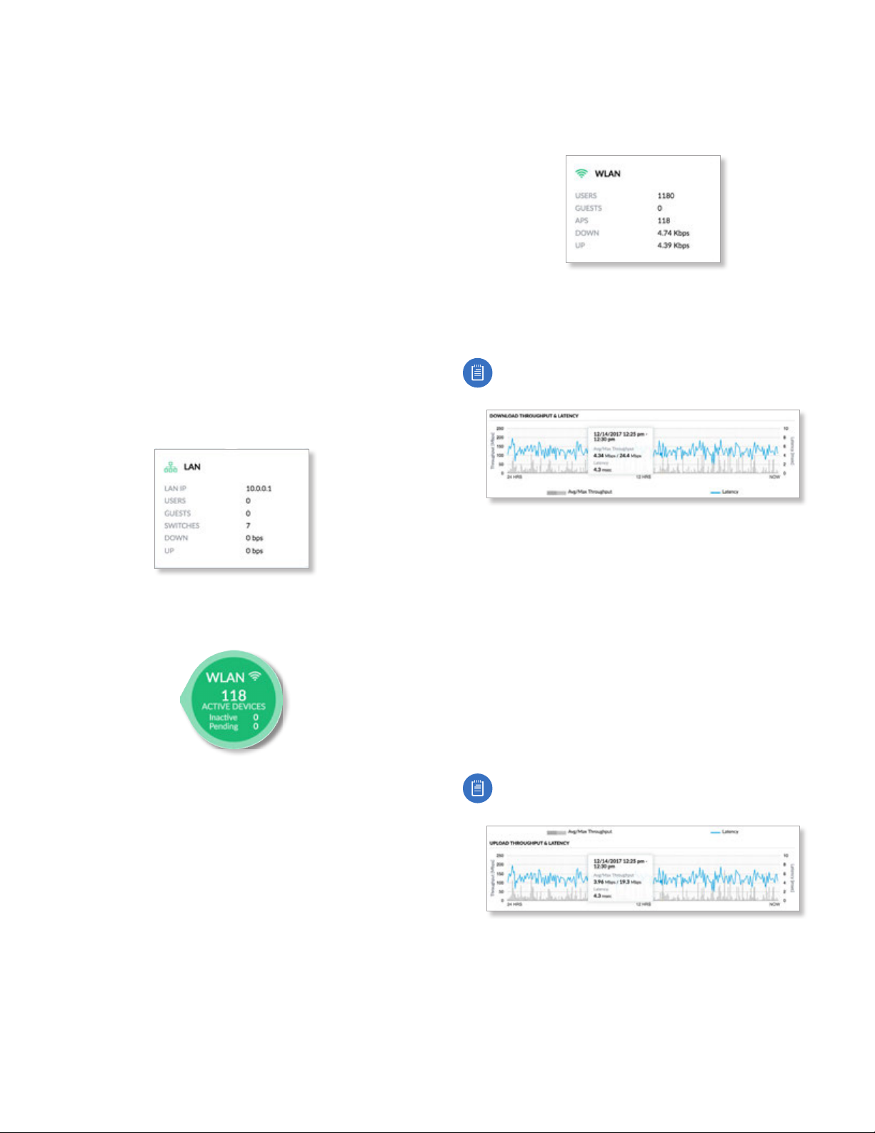
UniFi Controller User Guide
Chapter 4: Dashboard
Active Devices Displays the number of wired devices
adopted and active.
Inactive Displays the number of wired devices adopted
but not active.
Pending Displays the number of wired devices pending
adoption.
Status information Click the monitor to display the
following:
• LAN IP Displays the local IP address of the UniFi
Security Gateway.
• Users Displays the number of clients connected to the
wired network.
• Guests Displays the number of clients connected to the
guest wired network.
• Switches Displays the number of UniFi Switches
managed on this site.
• Down Displays the download rate of the wired
network(s).
• Up Displays the upload rate of the wired network(s).
• APs Displays the number of APs managed on this site.
• Down Displays the download rate of the wireless
network(s).
• Up Displays the upload rate of the wireless network(s).
Download Throughput & Latency
The historical chart displays the download traffic in terms
of throughput and latency over a 24-hour period.
Note: A UniFi Security Gateway must be active to
enable this chart.
WLAN
The basic details of the wireless network(s) are displayed.
The monitor is color-coded to indicate status:
Green The wireless network is active.
Red The wireless network is inactive.
Active Devices Displays the number of APs adopted and
active.
Inactive Displays the number of APs adopted but not
active.
Pending Displays the number of APs pending adoption.
Status information Click the monitor to display the
following:
• Users Displays the number of clients connected to the
primary wireless network(s).
• Guests Displays the number of clients connected to the
guest wireless network(s).
Avg/Max Throughput Average throughput is displayed
as a dark gray bar. Maximum throughput is displayed as a
light gray bar.
Latency Latency is displayed as a blue line.
Status information Click a specific point to display the
following about a date and time:
• Avg/Max Throughput Displays the average and
maximum throughput values.
• Latency Displays the latency value.
Upload Throughput & Latency
The historical chart displays the upload traffic in terms of
throughput and latency over a 24-hour period.
Note: A UniFi Security Gateway must be active to
enable this chart.
Avg/Max Throughput Average throughput is displayed
as a dark gray bar. Maximum throughput is displayed as a
light gray bar.
Latency Latency is displayed as a blue line.
Ubiquiti Networks, Inc.
65
Page 72
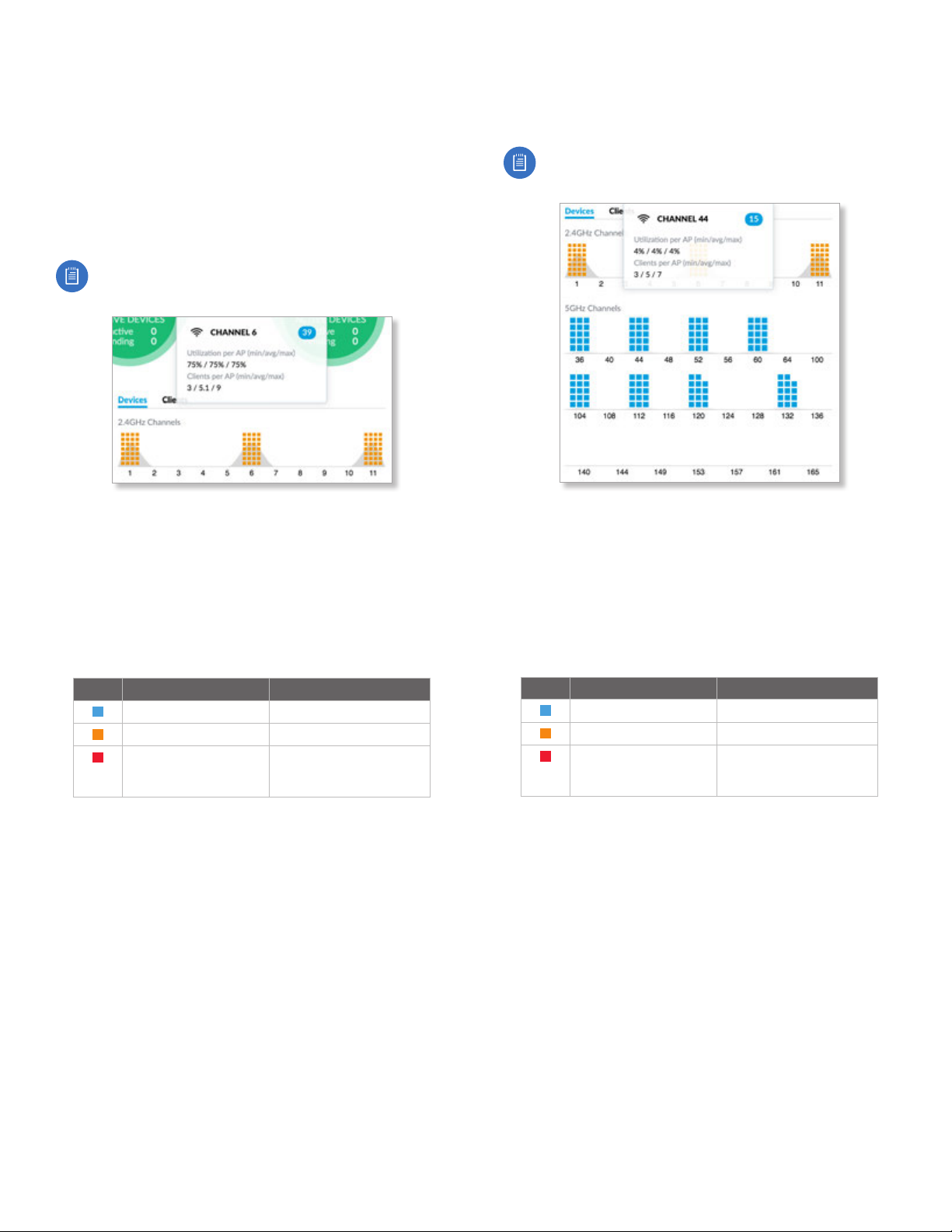
Chapter 4: Dashboard
UniFi Controller User Guide
Status information Click a specific point to display the
following about a date and time:
• Avg/Max Throughput Displays the average and
maximum throughput values.
• Latency Displays the latency value.
Devices on 2.4 GHz Radio Band
The 2.4 GHz Channel Occupancy Chart displays the
channel use of the 2.4 GHz band on a per-AP basis.
Note: At least one 2.4 GHz UniFi AP must be active
to enable this chart.
1-11 Each AP is represented by a square icon, which
is located in the channel to which the AP is currently
assigned. The gray peak associated with each channel
indicates the relative percentage of channel utilization on
each assigned channel.
The color of the square icon indicates the percentage of
channel utilization on each AP assigned to the displayed
channel:
Devices on 5 GHz Radio Band
The 5 GHz Channel Occupancy Chart displays the channel
use of the 5 GHz band on a per-AP basis.
Note: At least one 5 GHz UniFi AP must be active to
enable this chart.
(Channels) Each AP is represented by a square icon,
which is located in the channel to which the AP is currently
assigned. The gray peak associated with each channel
indicates the relative percentage of channel utilization on
each assigned channel.
The color of the square icon indicates the percentage of
channel utilization on each AP assigned to the displayed
channel:
Color Status Percentage of Utilization
Ideal Low: <50%
Acceptable Medium: 50-75%
Warning
(potential performance
implications)
High: >75%
Over time, if channel utilization is consistently high on a
given channel, this may indicate a need for improved AP
channel assignments.
Status information Click a specific channel to display the
following information:
• Utilization per AP The minimum, average, and
maximum percentage are displayed.
• Clients per AP The minimum, average, and maximum
number of clients are displayed.
Color Status Percentage of Utilization
Ideal Low: <50%
Acceptable Medium: 50-75%
Warning
(potential performance
implications)
High: >75%
Over time, if channel utilization is consistently high on a
given channel, this may indicate a need for improved AP
channel assignments.
Status information Click a specific channel to display the
following information:
• Utilization per AP The minimum, average, and
maximum percentage are displayed.
• Clients per AP The minimum, average, and maximum
number of clients are displayed.
66
Ubiquiti Networks, Inc.
Page 73
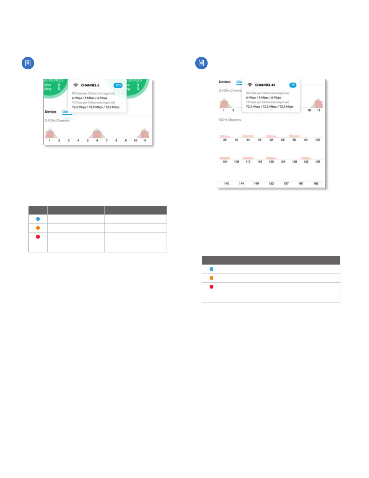
UniFi Controller User Guide
Chapter 4: Dashboard
Clients on 2.4 GHz Radio Band
Click Clients above the Channel Occupancy Charts to
display the number of clients on each specific channel.
Note: At least one 2.4 GHz UniFi AP must be active
to enable this chart.
1-11 Each client is represented by a circular icon, which is
located in the channel it is using. The gray peak associated
with each channel indicates the relative amount of traffic.
The color of the circular icon represents the quality of
the RX rate associated with the client. This indicates the
quality of the connection between the client and AP:
Color Status RX Rate
Ideal High: > 40 Mbps
Acceptable Medium: < 40 Mbps
Warning
(poor performance with
this client)
Low: < 10 Mbps
Clients on 5 GHz Radio Band
Click Clients above the Channel Occupancy Charts to
display the number of clients on each specific channel.
Note: At least one 5 GHz UniFi AP must be active to
enable this chart.
(Channels) Each client is represented by a circular icon,
which is located in the channel it is using. The gray peak
associated with each channel indicates the relative
amount of traffic.
The color of the circular icon represents the quality of
the RX rate associated with the client. This indicates the
quality of the connection between the client and AP:
Over time, if client rates are consistently poor, this may
indicate a need for greater or improved coverage, or may
help identify clients experiencing issues.
Status information Click a specific channel to display the
following information:
• RX Rate per Client The minimum, average, and
maximum RX rates are displayed.
• TX Rate per Client The minimum, average, and
maximum TX rates are displayed.
Color Status RX Rate
Ideal High: > 40 Mbps
Acceptable Medium: < 40 Mbps
Warning
(poor performance with
this client)
Low: < 10 Mbps
Over time, if client rates are consistently poor, this may
indicate a need for greater or improved coverage, or may
help identify clients experiencing issues.
Status information Click a specific channel to display the
following information:
• RX Rate per Client The minimum, average, and
maximum RX rates are displayed.
• TX Rate per Client The minimum, average, and
maximum TX rates are displayed.
Ubiquiti Networks, Inc.
67
Page 74

Chapter 4: Dashboard
UniFi Controller User Guide
Devices
UniFi devices are displayed.
Traffic Displays the total number of devices and a
color-coded breakdown of the device types.
WLAN Displays the number of wireless devices.
LAN Displays the number of wired devices.
WAN Displays the number of gateway devices.
Status information Click a specific device category to
display the device models and their quantities.
Clients
Network clients are displayed.
Note: The DPI feature must be enabled to display
client information.
Traffic Displays the total number of devices and a
color-coded breakdown of the device types.
Ubiquiti Displays the number of Ubiquiti clients.
(Various) Displays the number of clients that belong in
each of the remaining client categories.
Other Displays the number of clients that don’t belong in
the aforementioned categories.
Status information Click a specific client category to
display the client category name.
Deep Packet Inspection
Deep Packet Inspection (DPI) is more advanced than
conventional Stateful Packet Inspection (SPI) filtering for
traffic analysis. Ubiquiti’s proprietary DPI engine includes
the latest application identification signatures to track
which applications (and IP addresses) are using the most
bandwidth.
The DPI feature requires the following:
• A UniFi Security Gateway must be active to enable this
feature.
• DPI must be enabled on the Settings > Site screen. See
“Settings > Site” on page 21 for more information.
Traffic Displays the total amount of traffic and a color-
coded breakdown of the traffic types.
Network Protocols Displays the amount of data that is
identified as network protocol traffic.
Streaming Media Displays the amount of data that is
identified as streaming media.
Web Displays the amount of data that is identified as
web-related traffic.
File Transfer Displays the amount of data that is
identified as files being transferred.
Social Network Displays the amount of data that is
identified as social networking traffic.
Other Displays the amount of data that doesn’t belong in
the aforementioned categories.
Status information Click a specific traffic category to
display the traffic category name and amount of data.
68
Ubiquiti Networks, Inc.
Page 75
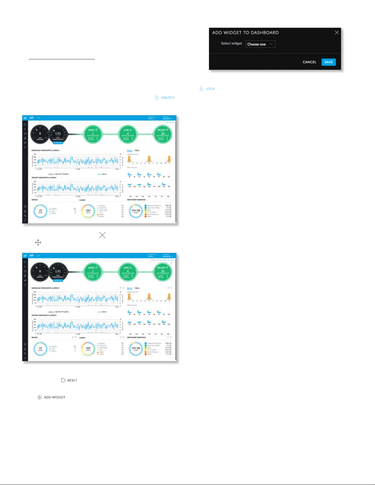
UniFi Controller User Guide
Dynamic Dashboard (beta)
You can enable the Dynamic Dashboard (beta) setting
using your account preferences. For more information, go
to ”Username” on page 18.
Once Dynamic Dashboard (beta) is enabled, then you can
customize the Dashboard display. You can move, add, or
remove the sections of the display. (Each section uses a
widget for its status information.)
Unlock The Dashboard is locked by default. Click
to unlock the display.
Chapter 4: Dashboard
Lock Once you are finished with your changes, click
to save your display options.
Once unlocked, you can click to remove a widget or
click to move a widget.
Reset You can reset the Dashboard to its factory default
settings. Click
Add Widget You can add widgets back to the display.
Click .
• Select widget Select the widget you want to add.
• Save Click to apply changes.
• Cancel Click to discard changes.
.
Ubiquiti Networks, Inc.
69
Page 76

Chapter 4: Dashboard
UniFi Controller User Guide
70
Ubiquiti Networks, Inc.
Page 77
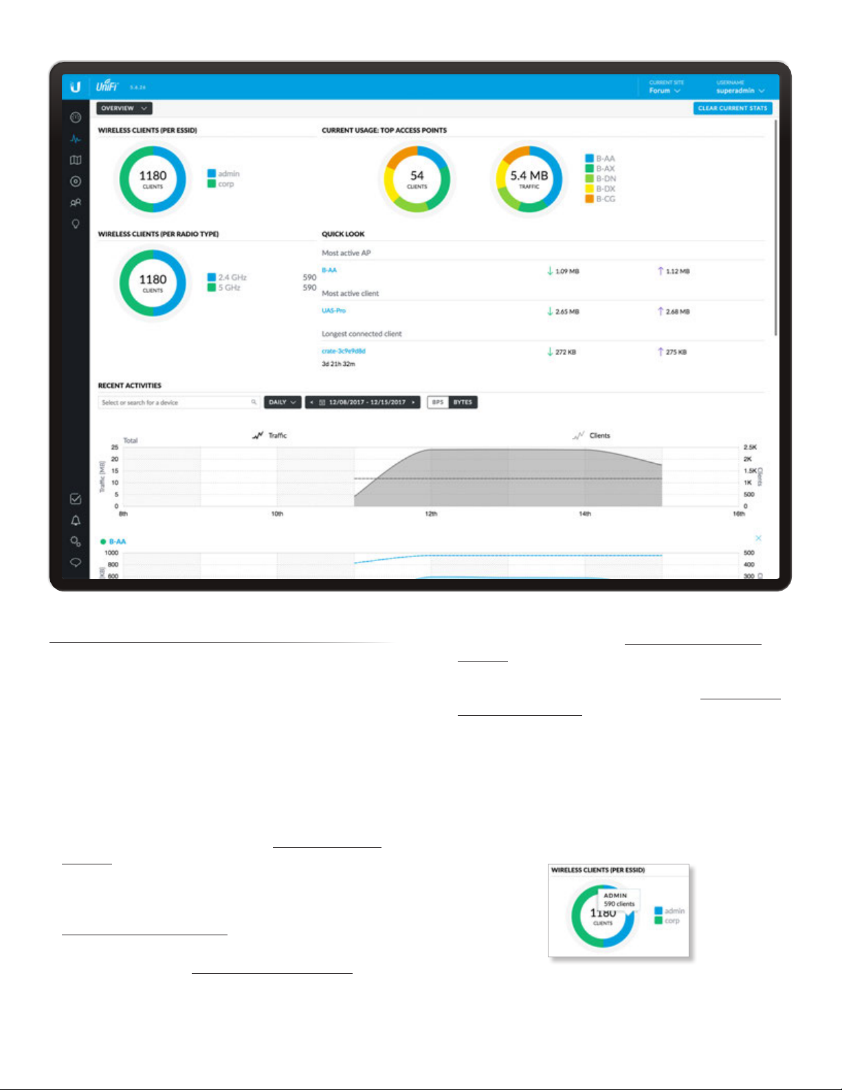
UniFi Controller User Guide
Chapter 5: Statistics
Chapter 5: Statistics
The Statistics screen provides a visual representation
of the clients and network traffic connected to your
managed UniFi network.
Here are the available options:
• Overview The default view describes the wireless
clients and network traffic. Please refer to the next
column for more information.
• Traffic Stats (Available if you have a UniFi Security
Gateway with the DPI feature enabled.) The Traffic
Stats screen describes the network traffic by category,
application, and client usage. Go to “Traffic Stats” on
page 73 for more information.
• Performance The Performance screen describes
the device performance by CPU and memory usage,
traffic, packets, dropped packets, and errors. Go to
“Performance” on page 76 for more information.
• Switch Stats The Switch Stats screen describes the ports
and port traffic. Go to “Switch Stats” on page 77 for
more information.
• Speed Test Stats The Speed Test Stats screen describes
the speed test results. Go to “Speed Test Stats” on
page 78 for more information.
• Debugging Metrics This beta offers wireless device
and client statistics for debugging. Go to “Debugging
Metrics” on page 78 for more information.
Overview
The Overview screen describes the usage by wireless
clients and UniFi Access Points.
Clear Current Stats Reset the current statistics to
startover.
Wireless Clients (Per ESSID)
# of Clients A visual pie chart represents the client
distribution amongst the wireless networks (SSIDs). Click
the chart for the number of clients per network.
Ubiquiti Networks, Inc.
71
Page 78
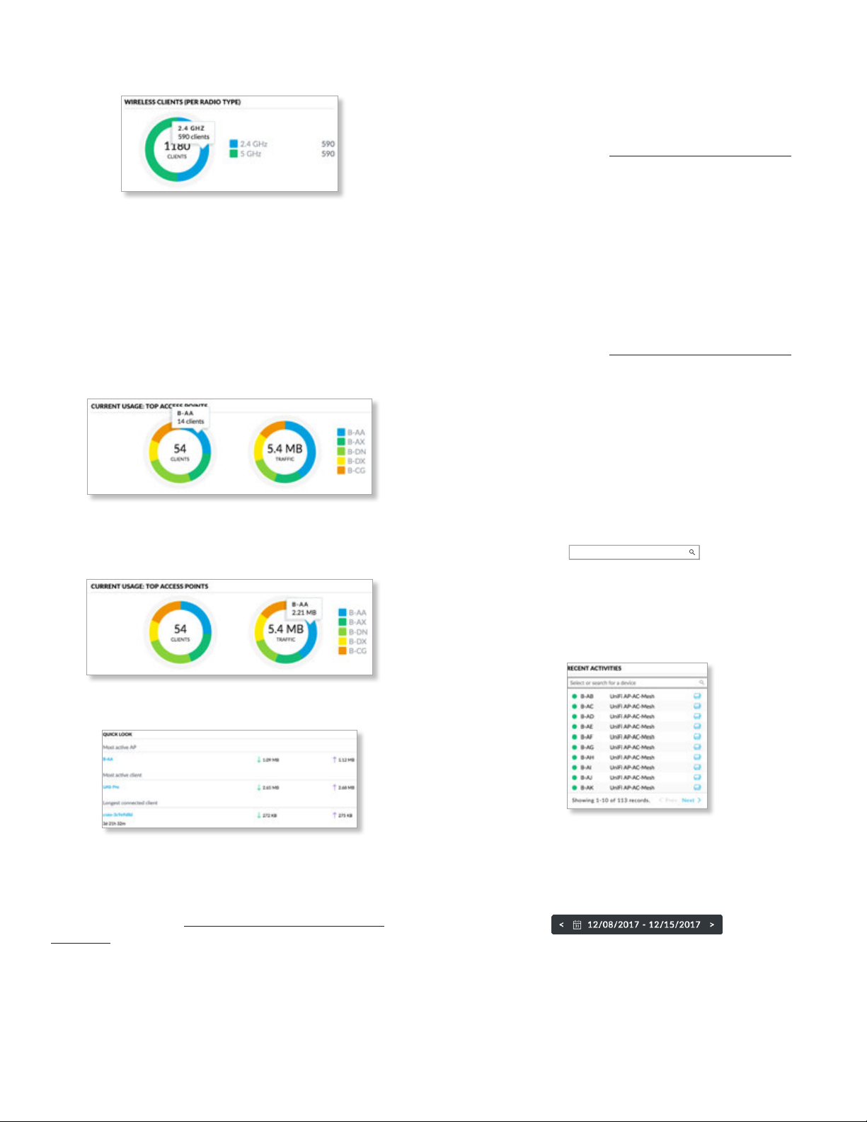
Chapter 5: Statistics
UniFi Controller User Guide
Wireless Clients (Per Radio Type)
# of Clients A visual pie chart represents the client
distribution between the radio bands. Click the chart for
the number of clients per band.
Current Usage: Top Access Points
The details of the most active Access Points in current use
are displayed.
# of Clients A pie chart represents the client distribution
on the most active Access Points. Click the chart for the
number of clients per specified AP.
Most Active Client
The details of the most active client in current use are
displayed:
Name or MAC address You can click this link to open the
Client Details screen. See “Client Details” on page 147
for additional information.
Download Displays the total amount of data downloaded
by the client.
Upload Displays the total amount of data uploaded by
the client.
Longest Connected Client
The details of the client connected for the longest period
of time are displayed:
Name or MAC address You can click this link to open the
Client Details screen. See “Client Details” on page 147
for additional information.
Uptime Displays the duration of time the client has been
connected.
Download Displays the total amount of data downloaded
by the client.
Upload Displays the total amount of data uploaded by
the client.
Traffic A pie chart represents traffic on the most active
Access Points. Click the chart for the amount of traffic per
specified AP.
Quick Look
Most Active AP
The details of the most active Access Point are displayed:
Name or MAC address You can click this link to open the
AP Details screen. See “UniFi Access Point Details” on
page 131 for additional information.
Download Displays the total amount of data downloaded
by the AP.
Upload Displays the total amount of data uploaded by
the AP.
Recent Activities
The details of recent network activities are displayed.
Recent Activities
number of clients and amount of traffic by UniFi AP. The
drop-down list displays managed UniFi APs by name or
MAC address. Select the appropriate AP or enter the text
you want to search for. Simply begin typing; there is no
need to press Enter.
(daily) The default view. Select 5 minutes, hourly, or
daily to change the duration interval.
Date Click either arrow to change the date in one-day
increments.
Select or search for a device
You can view the
72
Ubiquiti Networks, Inc.
Page 79
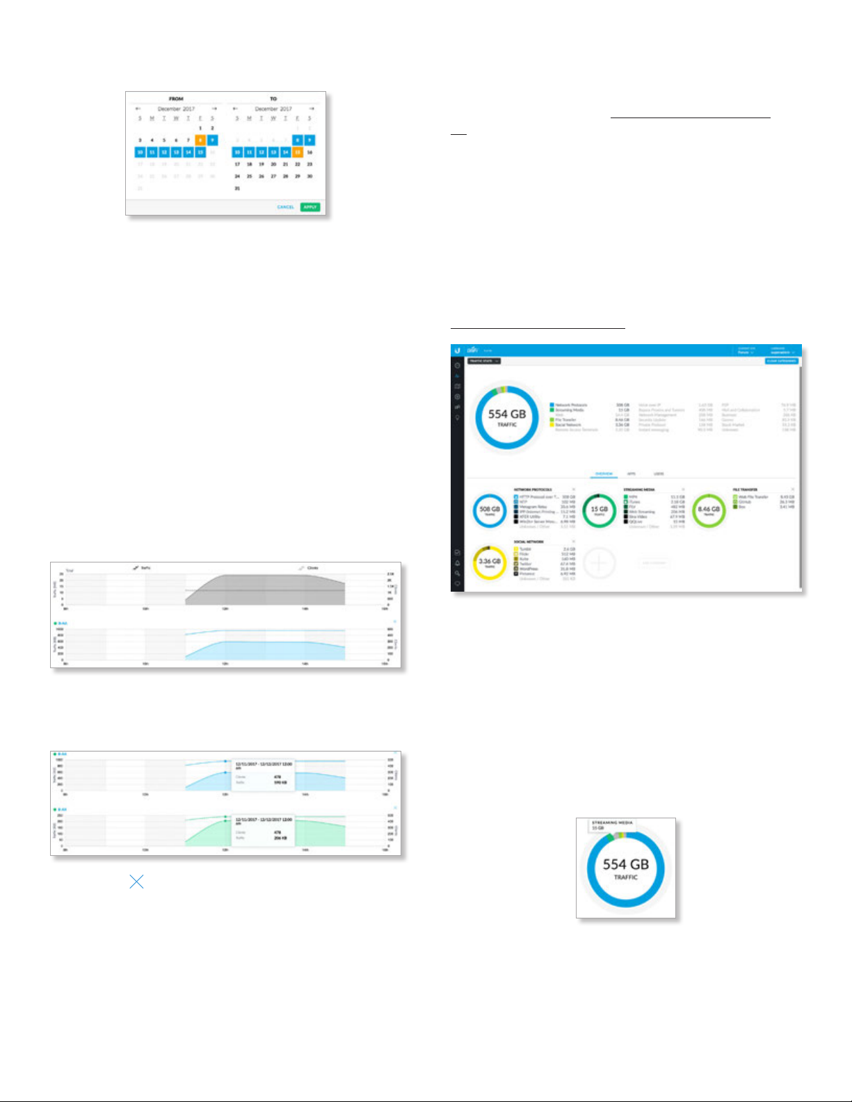
UniFi Controller User Guide
Chapter 5: Statistics
Click the date to display the calendar.
• Calendar Click a specific date to display its statistics.
For a range of dates, click both the start and end dates,
which are color-coded orange; the intervening dates
are color-coded blue. Click either arrow to change the
calendar in one-month increments.
- Apply Click to save changes.
- Cancel Click to cancel changes.
(bytes) The default view. Select bps to change the unit of
measurement.
The top graph displays the total number of clients and
amount of data for all APs.
Clients In the graph, a dashed line displays the number of
clients connected during the selected time period. Click a
point on the line to display the exact number.
Traffic In the graph, a solid line displays the network
traffic during the selected time period. Click a point on the
line to display the specific amount of data.
Traffic Stats
(Available if you have a UniFi Security Gateway with the
DPI feature enabled. Go to “Settings > Site” on page
21 for more information.) The Traffic Stats screen
describes the network traffic by application usage.
Deep Packet Inspection (DPI) is more advanced than
conventional Stateful Packet Inspection (SPI) filtering for
traffic analysis. Ubiquiti’s proprietary DPI engine includes
the latest application identification signatures to track
which applications (and IP addresses) are using the most
bandwidth.
Clear Categories Reset the category listings. To reset
the statistics to start over, go to the Settings > DPI screen
and click Clear CPI Counters. For more information go to
“Settings > DPI” on page 55.
When you select an AP, an additional graph that is
color-coded to the selected AP appears. (You can select
multiple APs for filtering.)
You can click to remove an AP from display.
Applications are organized by category, such as Network
Protocols, Streaming Media, Web, File Transfer, and Social
Network. The total amount of traffic is broken down by
category.
Amount of Traffic A pie chart represents the traffic
distribution by the most popular categories. Click the
chart for the amount of traffic per category.
A list displays a comprehensive breakdown of the traffic by
category. You can click any category to have it displayed
with a detailed breakdown of the application usage within
that category.
Ubiquiti Networks, Inc.
73
Page 80
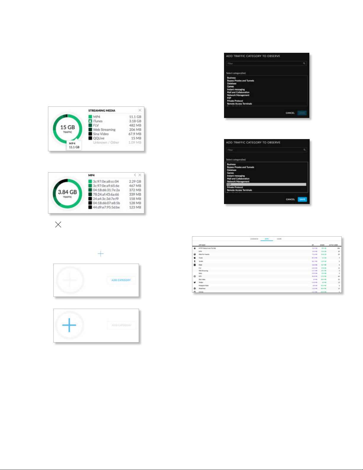
Chapter 5: Statistics
UniFi Controller User Guide
There are three views available: Overview, Apps, and Users.
Overview
The most popular categories are displayed with the
amount of traffic broken down further by application.
Amount of Traffic A pie chart represents the traffic
distribution by the most popular applications. Click the
chart for the amount of traffic per application.
A list displays a comprehensive breakdown of the traffic
by application.
Click a specific application to display a list of clients.
2. Select a category. You can also enter a keyword in the
Filter field; simply begin typing; there is no need to
press Enter.
3. Click Save.
You can click to remove a category from display.
Add Category
To add a new category for display, follow these steps:
1. Click Add Category or the sign.
Apps
The most popular applications are displayed.
(icon) Displays the representative icon, if applicable.
App Name Displays the name or description.
Up Displays the total amount of data uploaded by the
app.
Down Displays the total amount of data downloaded by
the app.
Active Users Displays the number of users currently
using the app.
74
Ubiquiti Networks, Inc.
Page 81
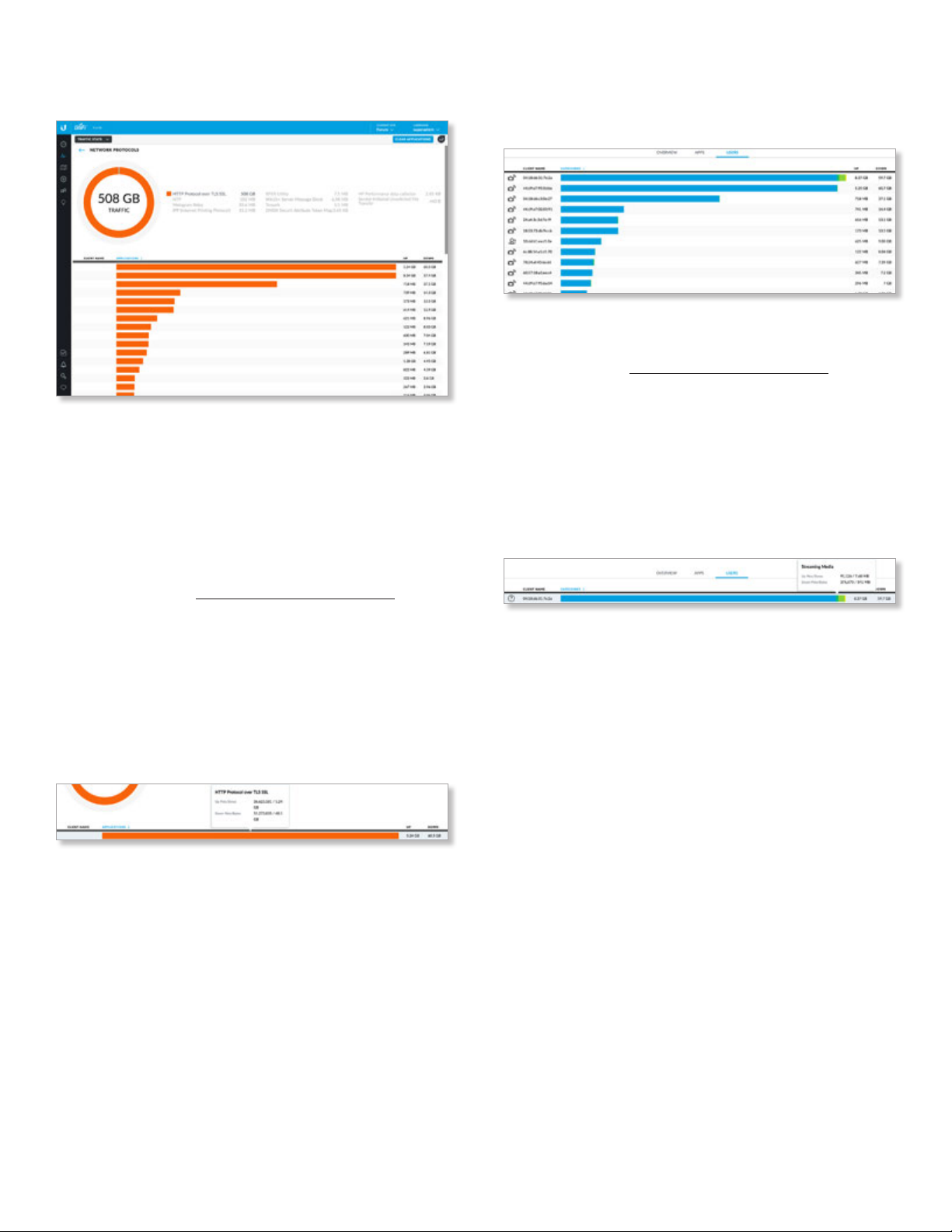
UniFi Controller User Guide
Chapter 5: Statistics
Click any app to display the amount of traffic broken down
further by client.
Clear Applications Reset the current statistics to
startover.
(amount of traffic) A pie chart represents the traffic
distribution by the relevant applications. Click the chart for
the specific amount of traffic per application.
A list displays a comprehensive breakdown of the
application traffic by client.
• Client Name You can click this link to open the Client
Details screen. See “Client Details” on page 147 for
additional information.
• Applications The bar graph displays the percentage of
the app traffic generated by the client. Click to display
additional statistics:
- Up Pkts/Bytes Displays the number of packets and
bytes uploaded.
- Down Pkts/Bytes Displays the number of packets
and bytes downloaded.
Users
The users are displayed with the amount of traffic broken
down further by category.
(icon) The client device icon is displayed if available.
Client Name You can click this link to open the Client
Details screen. See “Client Details” on page 147 for
additional information.
Categories The bar graph displays the percentage of
the traffic per category generated by the client. Click to
display additional statistics:
• Up Pkts/Bytes Displays the number of packets and
bytes uploaded.
• Down Pkts/Bytes Displays the number of packets and
bytes downloaded.
Up Displays the total amount of data uploaded by the
user for this app.
Down Displays the total amount of data downloaded by
the user for this app.
• Up Displays the total amount of data uploaded by the
app for this client.
• Down Displays the total amount of data downloaded
by the app for this client.
Ubiquiti Networks, Inc.
75
Page 82
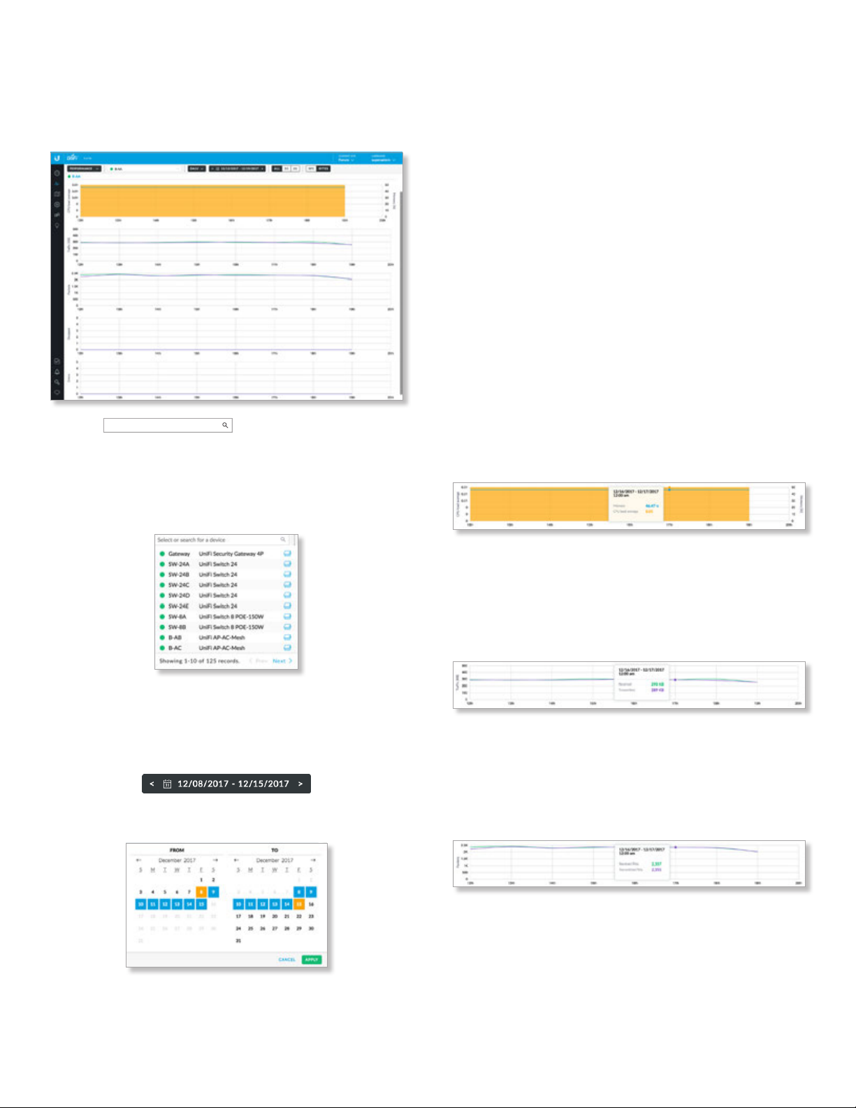
Chapter 5: Statistics
UniFi Controller User Guide
Performance
The Performance screen describes the device performance
by CPU and memory usage, traffic, packets, dropped
packets, and errors.
(device)
performance statistics by device. The drop-down list
displays managed UniFi devices by name or MAC address.
Select the appropriate device or enter the text you want to
search for. Simply begin typing; there is no need to press
Enter.
Select or search for a device
You can view the
• Calendar Click a specific date to display its statistics.
For a range of dates, click both the start and end dates,
which are color-coded orange; the intervening dates
are color-coded blue. Click either arrow to change the
calendar in one-month increments.
- Apply Click to save changes.
- Cancel Click to cancel changes.
Additional display options will vary depending on the
device type:
• Gateway Click the port whose statistics you want to
view: LAN 1, LAN 2, WAN 1, or WAN 2.
• SW You can select the Switch Stats option for more
information.
• AP You have two options:
- (radio band) Select the radio band you want to view:
All, 5G, or 2G.
- (bytes) The default view. Select bps to change the
unit of measurement.
Multiple color-coded graphs are displayed. Click a point on
the line to display the specific values.
CPU and Memory
(daily) The default view. Select 5 minutes, hourly, or
daily to change the duration interval.
Date Click either arrow to change the date in one-day
increments.
Click the date to display the calendar.
CPU Load Average The graph displays the average load
on the CPU during the selected time period.
Memory (%) The graph displays the percentage of
memory used during the selected time period.
Traffic
Received A solid green line displays the bytes of data
received.
Transmitted A solid purple line displays the bytes of data
transmitted.
Packets
Received A solid green line displays the number of
packets received.
Transmitted A solid purple line displays the number of
packets transmitted.
76
Ubiquiti Networks, Inc.
Page 83
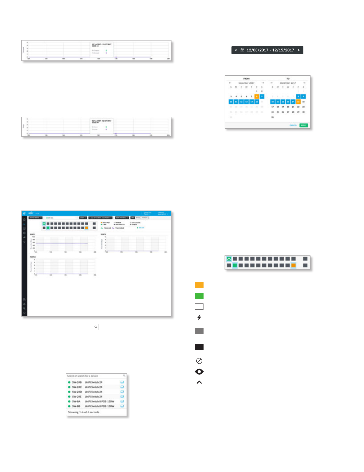
UniFi Controller User Guide
Chapter 5: Statistics
Dropped
Received A solid green line displays the number of
receive packets dropped.
Transmitted A solid purple line displays the number of
transmit packets dropped.
Errors
Received A solid green line displays the number of
receive errors.
Transmitted A solid purple line displays the number of
transmit errors.
Switch Stats
The Performance screen describes the ports and port
traffic of the selected UniFi Switch.
Date Click either arrow to change the date in one-day
increments.
Click the date to display the calendar.
• Calendar Click a specific date to display its statistics.
For a range of dates, click both the start and end dates,
which are color-coded orange; the intervening dates
are color-coded blue. Click either arrow to change the
calendar in one-month increments.
- Apply Click to save changes.
- Cancel Click to cancel changes.
Additional display options are available:
• Sort Click the appropriate sort order: Natural
(numerical port order), Transmitted, Received, or Total.
• (bps) The default view. Select bytes or packets to
change the unit of measurement.
The upper part of the detached popup screen has an icon
for each port.
(device)
their traffic by UniFi Switch. The drop-down list displays
managed UniFi Switches by name or MAC address. Select
the appropriate switch or enter the text you want to
search for. Simply begin typing; there is no need to press
Enter.
(daily) The default view. Select 5 minutes, hourly, or
daily to change the duration interval.
Ubiquiti Networks, Inc.
Select or search for a device
You can view the ports and
Indicates a 10/100 Mbps connection.
Indicates a 1 Gbps (1000 Mbps) connection.
Indicates a 10 Gbps connection.
Indicates 1 Gbps (1000 Mbps) connection with PoE.
Indicates the connection is disabled (no network or
VLAN is enabled).
Indicates no connection (the network or VLAN is
enabled, but the port is not in use).
Indicates STP blocking.
Indicates mirroring mode.
Indicates an uplink.
77
Page 84
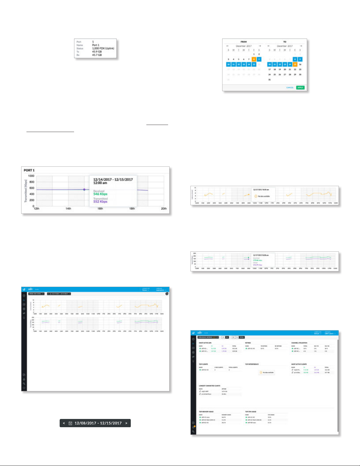
Chapter 5: Statistics
UniFi Controller User Guide
Place your cursor over a port to view details.
• Port Displays the port number.
• Name Displays the name of the port.
• Status Displays the connection speed and duplex mode.
• TX Displays the amount of data transmitted.
• RX Displays the amount of data received.
• Profile Displays the Switch Port profile assigned to it.
Switch Port profiles are configured in Settings > “Switch
Ports” on page 46.
Click an active port to display its color-coded graph. Click
a point on the line to display the specific values.
Port
Click the date to display the calendar.
• Calendar Click a specific date to display its statistics.
For a range of dates, click both the start and end dates,
which are color-coded orange; the intervening dates
are color-coded blue. Click either arrow to change the
calendar in one-month increments.
- Apply Click to save changes.
- Cancel Click to cancel changes.
Two color-coded graphs are displayed. Click a point on the
line to display the specific values.
Latency
Received A solid green line displays the bytes of data
received.
Transmitted A solid purple line displays the bytes of data
transmitted.
Speed Test Stats
The Speed Test Stats screen describes the speed test
results.
Latency Displays the amount of time it takes a packet
to travel from the UniFi Security Gateway to the service
provider’s gateway.
Speed
Download Displays the download speed.
Upload Displays the upload speed.
Debugging Metrics
The beta Debugging Metrics screen offers statistics about
your wireless devices and clients.
Date Click either arrow to change the date in one-day
increments.
78
Ubiquiti Networks, Inc.
Page 85
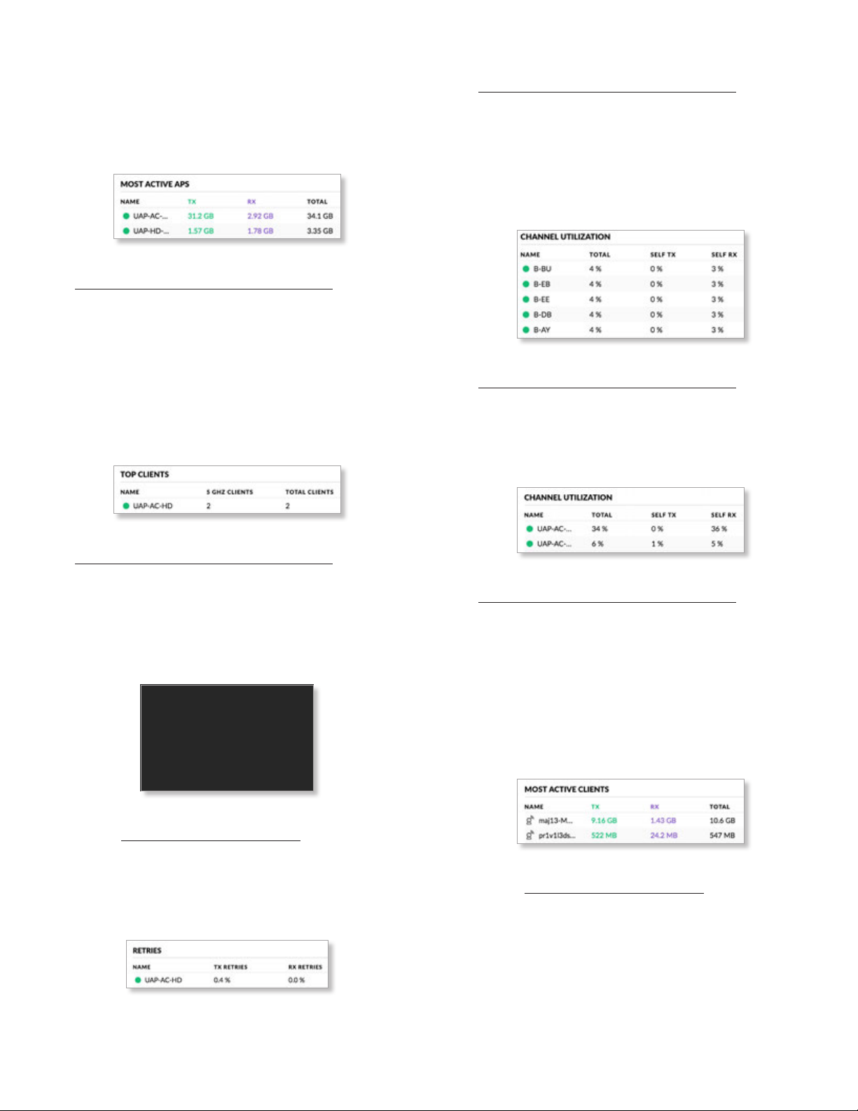
UniFi Controller User Guide
Chapter 5: Statistics
2G/5G Select the radio band whose statistics you want to
view.
RX/TX/Total Select the type of data you want to view: RX
(receive), TX (transmit), or Total (all data).
Most Active APs
Name You can click this link to open the AP Details screen.
See “UniFi Access Point Details” on page 131 for
additional information.
TX Displays the amount of data transmitted using the
selected radio band.
RX Displays the amount of data received using the
selected radio band.
Total Displays the amount of data transmitted and
received using the selected radio band.
Top Clients
Name You can click this link to open the AP Details screen.
See “UniFi Access Point Details” on page 131 for
additional information.
TX Retries Displays the percentage of data transmitted
that is comprised of retries.
RX Retries Displays the percentage of data received that
is comprised of retries.
Top Interference
Name You can click this link to open the AP Details screen.
See “UniFi Access Point Details” on page 131 for
additional information.
Interference Displays the percentage of interference
experienced by the AP.
Channel Utilization
Name You can click this link to open the AP Details screen.
See “UniFi Access Point Details” on page 131 for
additional information.
_ GHz Clients Displays the number of clients using the
selected radio band.
Total Clients Displays the total number of clients.
Longest Connected Clients
Name You can click this link to open the Client Details
screen. See “Client Details” on page 147 for additional
information.
Uptime Displays the duration of time the client has been
connected.
Retries
Name You can click this link to open the AP Details screen.
See “UniFi Access Point Details” on page 131 for
additional information.
Total Displays the total percentage of the channel that is
being used.
Self TX Displays the percentage of the channel that is
being used by the AP for transmitting data.
Self RX Displays the percentage of the channel that is
being used by the AP for receiving data.
Most Active Clients
Name You can click this link to open the Client Details
screen. See “Client Details” on page 147 for additional
information.
TX Displays the amount of data transmitted using the
selected radio band.
RX Displays the amount of data received using the
selected radio band.
Total Displays the amount of data transmitted and
received using the selected radio band.
Ubiquiti Networks, Inc.
79
Page 86
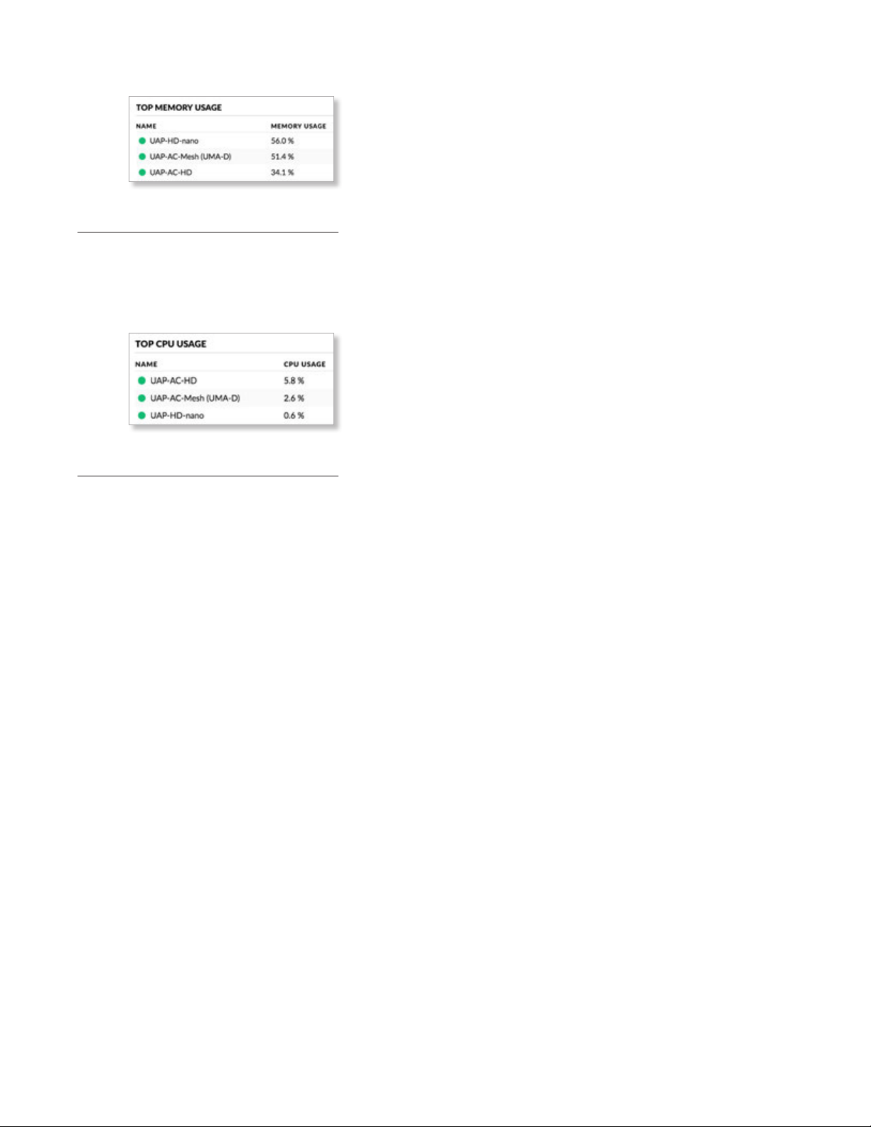
Chapter 5: Statistics
Top Memory Usage
Name You can click this link to open the AP Details screen.
See “UniFi Access Point Details” on page 131 for
additional information.
Memory Usage Displays the percentage of device
memory being used.
Top CPU Usage
UniFi Controller User Guide
Name You can click this link to open the AP Details screen.
See “UniFi Access Point Details” on page 131 for
additional information.
CPU Usage Displays the percentage of CPU processing
power being used.
80
Ubiquiti Networks, Inc.
Page 87
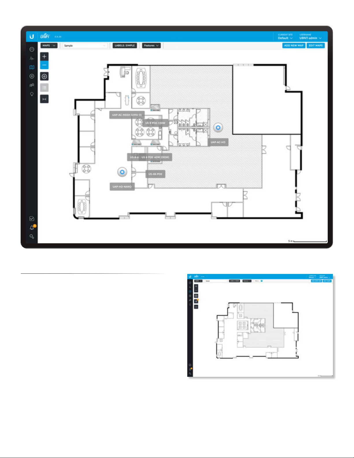
UniFi Controller User Guide
Chapter 6: Map
Chapter 6: Map
The Map screen allows you to upload custom map images
of your location(s) or use Google Maps™ for a visual
representation of your UniFi network. You can also view
the system topology. When you initially launch the UniFi
Controller application, a default map is displayed. The map
scale is shown in the legend at the bottom of the map.
Adding Custom Maps
To add a custom map, you must first create the image
using an illustration, image editing, or blueprint
application that exports a file in .jpg, .gif, or .png
fileformat.
Once you’ve created the map, you can upload it to the
UniFi Controller software:
1. Click Add New Map.
Ubiquiti Networks, Inc.
81
Page 88
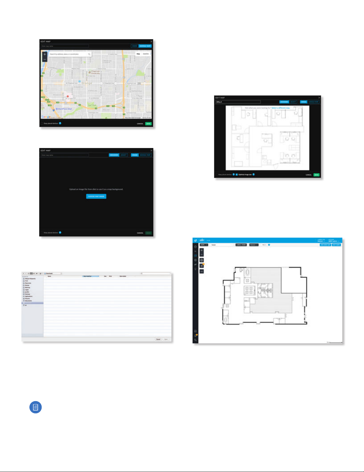
Chapter 6: Map
UniFi Controller User Guide
2. The default is Google Maps. Click Image.
3. Click Choose Map Image.
6. There are two tabs available, Designer (default) and
Legacy.
• Designer You have these features: predictive
coverage, 2D or 3D views, solid or heatmap views,
and the capability to add walls.
• Legacy You can filter by radio band and display
coverage and topology.
Click Save.
7. Click Done.
4. Locate the file to use as a map (valid file formats are
.jpg, .gif, and .png) and then click Open. If you do not
want to upload a file, click Cancel.
5. Enter a map name in the field provided.
Select Keep placed devices if you want to keep them
on the image you uploaded.
Keep Optimize image enabled if you want the UniFi
Controller to automatically reduce the size of a large
image for better performance.
Adding a Google Map
To add a Google Map to the UniFi Controller software
Mapview:
1. Click Add New Map.
82
Note: If the map is incorrect, click Select a
different map and try again.
Ubiquiti Networks, Inc.
Page 89
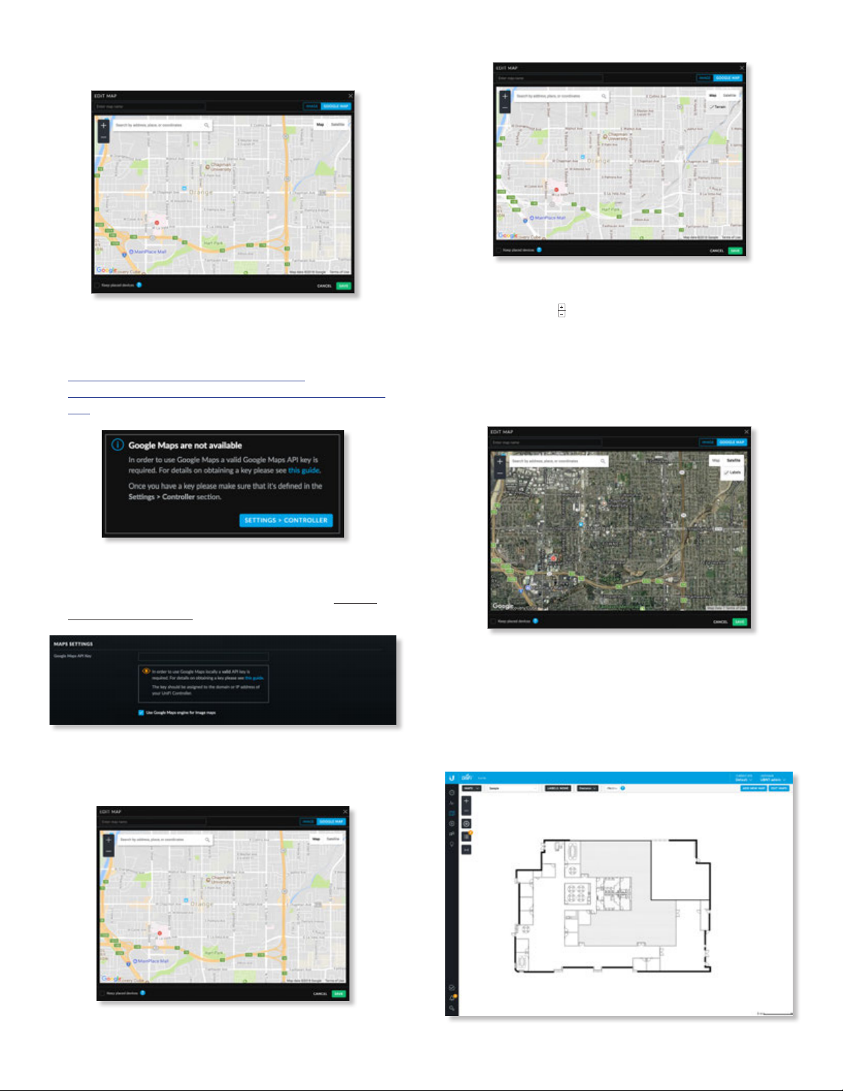
UniFi Controller User Guide
2. The default is Google Maps.
3. If Google Maps is not enabled yet, then enable this
feature by following the provided guide on how to
obtain a valid Google Maps API key:
https://developers.google.com/maps/
documentation/javascript/get-api-key#get-an-apikey
Chapter 6: Map
Terrain View
Use the tools to navigate the map or adjust the zoom
using the zoom control.
In the field provided, enter an address or the latitude
and longitude of a specific location. Then press Enter
or Return.
You can also click Satellite for a bird’s-eye view. Click
Labels to display street and location names.
4. Go to the Settings > Controller section and enter the API
key. Check the box to enable Use Google Maps engine
for Image maps. (For more information, go to “Maps
Setting” on page 56.) Click Apply Changes.
5. The default view is Map view, which looks like
a streetmap. Click Terrain to display enhanced
geographical details.
Enter a map name in the field provided and click Save.
6. Click Done.
Editing a Map
You can edit or delete a map.
1. Click Edit Maps.
Ubiquiti Networks, Inc.
Map View
83
Page 90
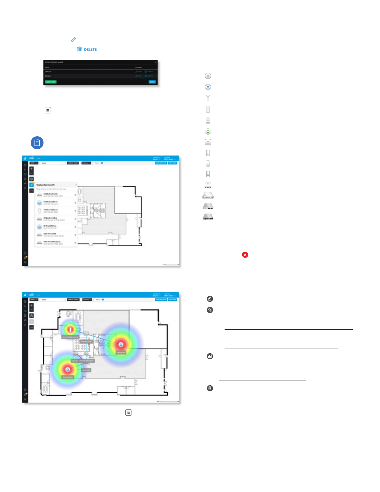
Chapter 6: Map
UniFi Controller User Guide
2. There is a list of existing maps.
• Edit Click
• Delete Click
EDIT
to make changes.
to remove the map.
Placing Devices on the Map
1. Click at the lower left.
2. Drag each device icon from the Unplaced Devices list to
the appropriate location on themap.
Note: If you cannot drag and drop a device,
ensure that you are logged in as a superadmin.
Device Information
Status
The device icon indicates the UniFi model (not all icons are
shown below):
UniFi AP Pro, UniFi AP AC Lite/LR/Pro/HD/SHD
UniFi AP AC EDU
UniFi AP AC Mesh
UniFi AP AC Mesh Pro
UniFi AP In-Wall/AP AC In-Wall
UniFi AP/AP LR
UniFi AP AC
UniFi AP AC Outdoor
UniFi AP Outdoor+
UniFi AP Outdoor5
UniFi Security Gateway
UniFi Security Gateway Pro
UniFi 24-Port Switch
Each device icon will appear in the area where you
placedit.
UniFi 48-Port Switch
The LED color of the icon indicates the device status.
• Blue/Green Indicates the device is connected.
• Red/Orange Indicates the device is disconnected. A
disconnected icon also marks the device icon.
Device Options
Click a UniFi icon to reveal options. Click the UniFi icon
again to hide them.
Lock Lock the device icon to its current location.
Details Display the Details screen. For more
information, go to the appropriate chapter:
• “UniFi Security Gateway Details” on page 115
• “UniFi Switch Details” on page 121
• “UniFi Access Point Details” on page 131
Statistics (Available for the second and third
generation UniFi AC APs only.) Displays the RF
Environment screen. For more information, go to
“RF Environment” on page 141.
Remove Remove the device icon from its location.
Once all devices have been placed the icon changes
from black to gray.
84
Ubiquiti Networks, Inc.
Page 91
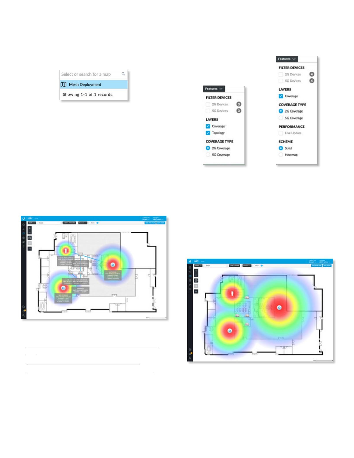
UniFi Controller User Guide
Chapter 6: Map
Map Display Options
(Map) If multiple maps have been uploaded, you can
select which map you want from the drop-down list or
search for keywords. There is no need to press Enter;
simply start typing.
Labels
Each device can be displayed with its name. If no
custom label is applied, the device’s MAC address will be
displayed.
Click this button to cycle between the following options
for label display:
None Do not display device labels.
Simple Display simple device labels containing the device
name only.
Detailed Display detailed device labels containing
the following information: device name, MAC address,
transmit/receive channel(s), number of users connected,
and number of guests connected.
Features
You have multiple display options available, some of
which vary depending on the Designer/Legacy option:
Legacy Designer
Filter Devices
2G Devices Displays the 2.4 GHz devices.
5G Devices Displays the 5 GHz devices.
Layers
Coverage Displays a visual representation of the wireless
range covered by any APs.
• __ dBm You can change the receiver sensitivity value
for more accurate coverage results. The default is
‑90dBm.
To change a name applied to a device, refer to Alias in the
appropriate section:
• “UniFi Security Gateway – Configuration” on page
117
• “UniFi Switch – Configuration” on page 127
• “UniFi Access Point – Configuration” on page 135
Ubiquiti Networks, Inc.
85
Page 92
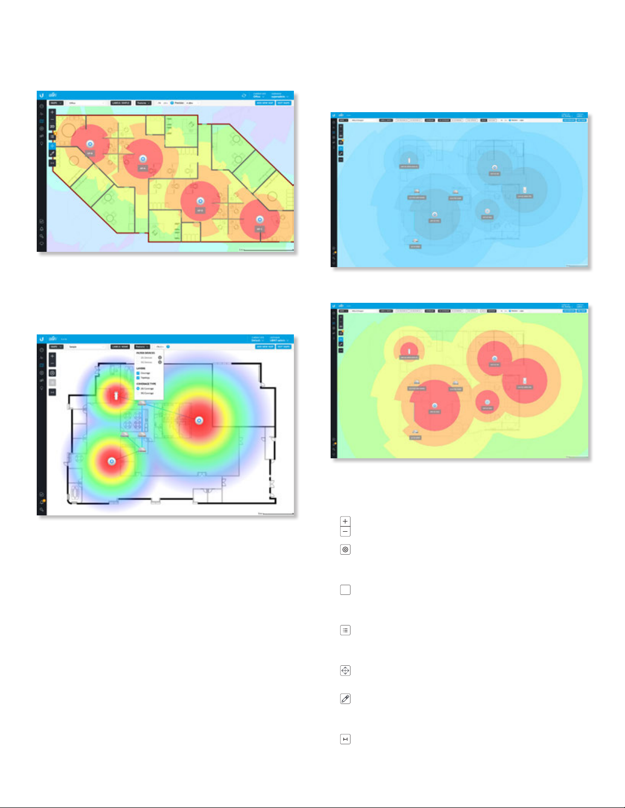
Chapter 6: Map
UniFi Controller User Guide
Precision (Designer option only) To fine-tune the
predictive coverage, select a dBm value from the dropdown list: 0.1dBm, 0.5 dBm, 1 dBm, 2 dBm, or 4 dBm.
Topology (Legacy option only.) Displays a visual
representation of the network configuration and
connections between any APs. A dashed line will indicate
the wirelessly connected AP and its uplink to a wired AP,
even if the wirelessly connected AP is isolated.
Scheme
(Available for Designer option) If Scheme is enabled, you
have the following options:
Solid Displays the coverage as solid colors.
Heatmap Displays the coverage as a heatmap.
Coverage Type
If Coverage is enabled, you have the following options:
2G Coverage Displays the coverage by 2.4 GHz devices.
5G Coverage Displays the coverage by 5 GHz devices.
Performance
(Available for Designer option) If Performance is enabled,
you have the following option:
Live Update Automatically updates in real time.
Additional Options
The left side of the map offers the following options:
Zoom Slider Use to zoom the map detail in
andout.
Devices (Legacy option only.) Click to toggle the
size of devices and their labels between small
andlarge.
2D/3D (Designer option only.) Click to toggle
2D
between two- and three-dimensional views of the
devices and walls.
Unplaced Devices
list to the appropriate location on themap. (This
option may require superadmin access.)
Move (Designer option only.) Click to move placed
devices or the map.
Draw Walls (Designer option only.) Use this option
to select the type of wall and then draw it on
theimage. Press ESC to end the wall.
Set Map Scale Use this option to define the scale
of the map. You will draw a line and define the
distance that the line represents.
Drag each device icon from the
86
Ubiquiti Networks, Inc.
Page 93
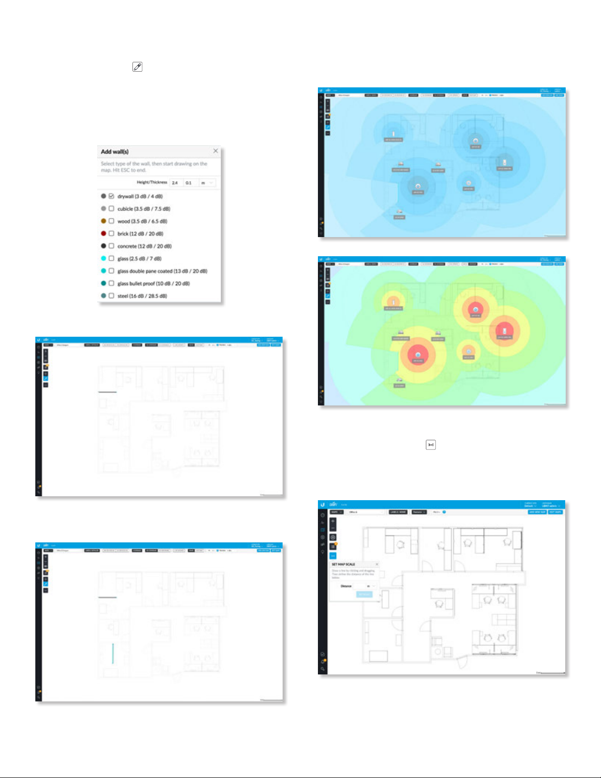
UniFi Controller User Guide
Chapter 6: Map
Drawing Walls
1. Click the draw walls button.
2. Select the type of wall you want to draw. You can
change the default height and thickness values in the
fields provided. By default they are specified in meters
but you can switch to feet using the drop-down menu
on the right.
3. Draw the wall and press ESC to end the wall.
After you have added the UniFi APs, the interference
caused by the walls will be predicted and displayed in
both the Solid and Heatmap views.
4. You can select a different type of wall and add it to the
map.
Setting the Map Scale
1. Click the set map scale button.
2. Click and hold to draw a line in the area that you want
to use to set the scale of the map. If you need to redraw
the line, just click and hold again to draw a new line.
Ubiquiti Networks, Inc.
87
Page 94
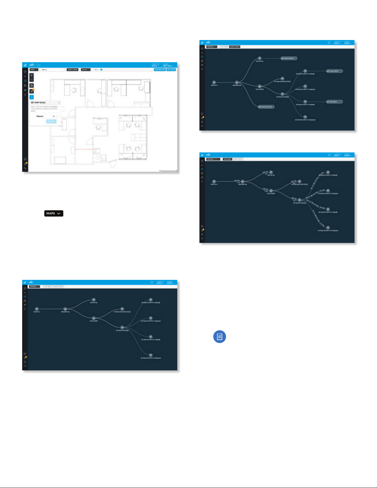
Chapter 6: Map
UniFi Controller User Guide
3. Enter the distance that the line represents in the
Distance field. By default, the distance is specified in
meters but you can switch to feet using the drop-down
menu on the right. Click Set Scale.
The legend at the bottom of the map shows the new scale
of the map.
System Topology
1. Click
drop-down menu.
2. The UniFi Controller displays a topology diagram of
your UniFi system.
The default view shows the entire topology tree,
except for client devices. Click any node to collapse the
branches below (to the right of) that node. Clicking the
root node collapses the entire tree.
and then select Topology from the
,
3. Click Show Clients to display client devices.
4. Click Link Labels to display labels on each link:
The labels provide the following information:
• Wired links
• Data rate in Mbps
• Duplex type: FDX for full duplex, HDX for half duplex
• Port number to which the device is connected
• Wireless links
• RSSI expressed as a percentage
• RSSI displayed in dBm
88
Note: The displayed RSSI value is from the AP
side of the link; i.e., it is how the AP hears the
client.
• Negotiation Rate (__ Mbps / __ Mbps)
Ubiquiti Networks, Inc.
Page 95
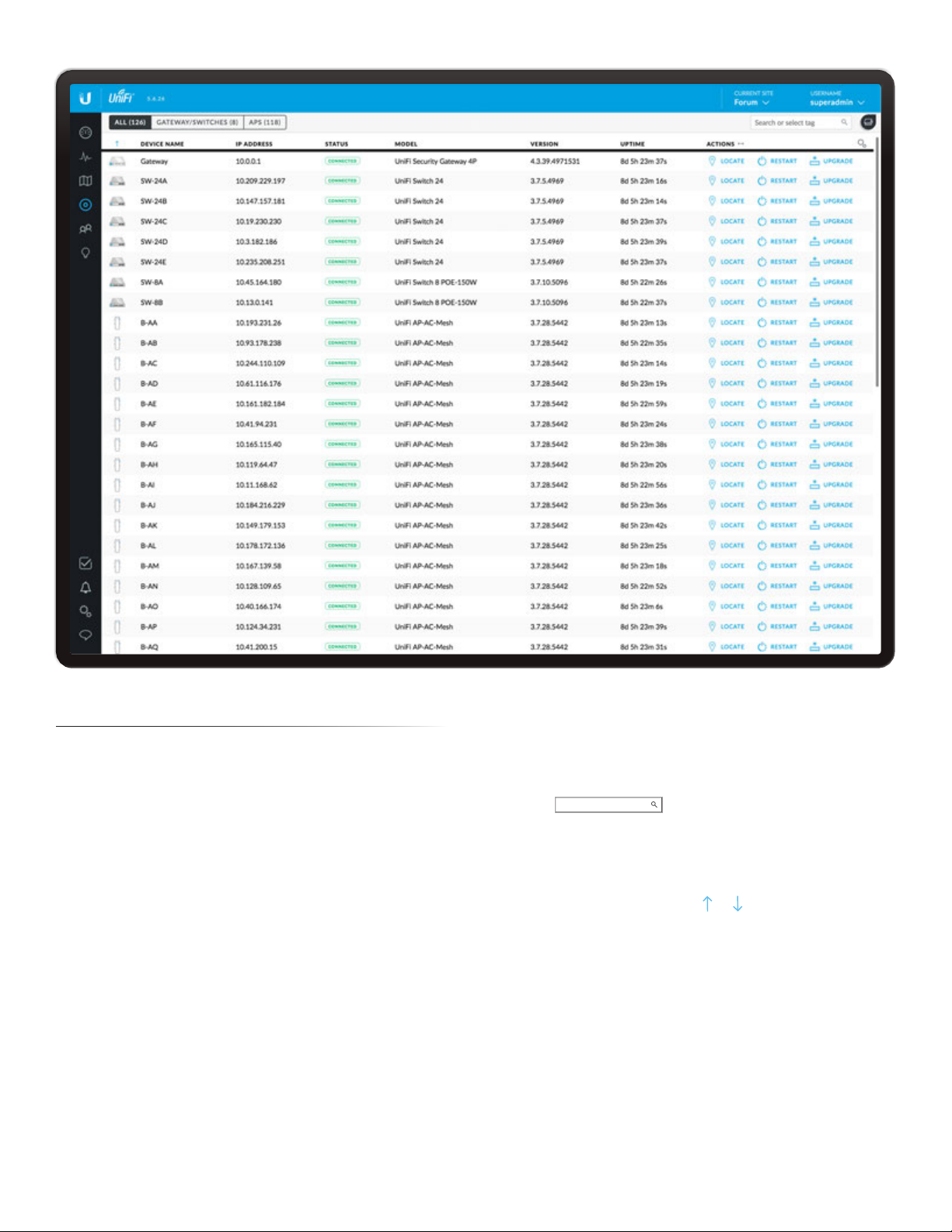
UniFi Controller User Guide
Chapter 7: Devices
Chapter 7: Devices
The Devices screen displays a list of UniFi devices
discovered by the UniFi Controller. You can click any of the
column headers to change the listorder.
You can apply one of the following primary filters:
• All Displays all UniFi devices.
• Gateway/Switches Displays all UniFi Security Gateways
and Switches.
• APs Displays all UniFi APs.
If the APs filter is applied, then another filter is available
(unless columns have been customized):
• Overview Displays the number of clients, amount
of data downloaded, amount of data uploaded, and
channel setting.
• Performance Displays the number of 2.4 GHz and
5GHz clients, overall transmit rate, overall receive rate,
transmit rates in the 2.4 GHz and 5GHz radio bands, and
channel setting.
• Config Displays the WLAN and radio settings for the
2.4GHz and 5 GHz radio bands.
Items per page Select how many results are displayed
per page: 10, 25, 50, or 100.
If there is more than one page of entries to display, click
the navigation controls or page numbers at the bottom
right of the screen to display different pages.
Search
search for. Simply begin typing; there is no need to press
Enter. You can also select a device tag (configured in the
Configuration section of a device).
(sort) You can click any column to sort the displayed list.
The selected column displays or to indicate ascending
or descending order.
The icon column sorts by state, and for connected devices
it also sorts by device type. This is the order:
• Connected Gateway
• Connected Switch
• Connected AP
• Any device that is being upgraded or provisioned
• Any device that is being adopted or is restarting
• Any device that is pending
• Any device that is disconnected or in an error state
Search or select tag
Enter the text you want to
Ubiquiti Networks, Inc.
89
Page 96
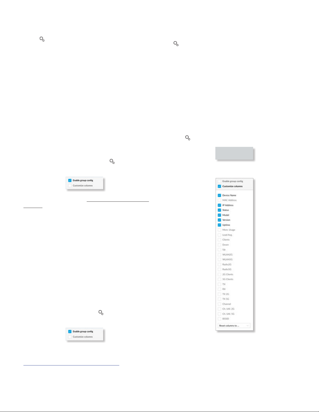
Chapter 7: Devices
UniFi Controller User Guide
After this sorting is applied, the sort order uses
alphabetical order according to the device name.
Settings To enable group or batch configuration or
customize the column layout, click this option.
• Enable Group Config (Switch) Use this feature to
configure an entire group of UniFi Switches at the same
time. The following settings can be changed with batch
configuration:
• Enable/disable LED
• Management VLAN
• Jumbo Frame
• Flow Control
• Spanning Tree
• Priority
• 802.1X Control
• Custom Upgrade
• Force Provision
• Forget These Devices
To configure a group of switches, click and then
select Enable group config.
• Customize Columns Each primary filter: All,
Gateway/Switches, or APs applies a default set of
columns to display. If you enable the Customize Columns
option, then the primary filter no longer changes the
columns.
The very first time you enable the Customize Columns
option, the UniFi Controller software will detect which
columns are currently visible and remember your
selection. For example:
1. Enable the Customize Columns option on the APs >
Performance screen.
2. Disable customization.
3. Apply the Gateway/Switches filter.
4. Enable the Customize Columns option again.
5. The columns of the APs > Performance screen will be
displayed.
Click to customize the columns used for display.
Select Customize columns.
For more information, go to “Group Configuration” on
page 92.
• Enable Group Config (AP) Use this feature to configure
an entire group of UniFi APs at the same time. The
following AP settings can be changed with batch
configuration:
• Enable/disable LED
• Radio Channel
• Radio Channel Width
• Radio Transmit Power
• WLAN Groups
• Custom Upgrade
• Force Provision
• Disable These Devices
• Forget These Devices
To configure a group of APs, click and then select
Enable group config.
For detailed instructions and information on AP group
configuration, refer to the following online help article:
ubnt.link/UniFi-AP-Group-Configuration
You can select additional columns for display.
- Reset columns to Click the drop-down at the bottom
of the Customize columns screen to display the Reset
columns to ... options. The option you select will apply
no matter which primary filter: All, Gateway/Switches,
or APs, you select. This resets the columns (the UniFi
Controller software will not remember your original
selection).
90
Ubiquiti Networks, Inc.
Page 97
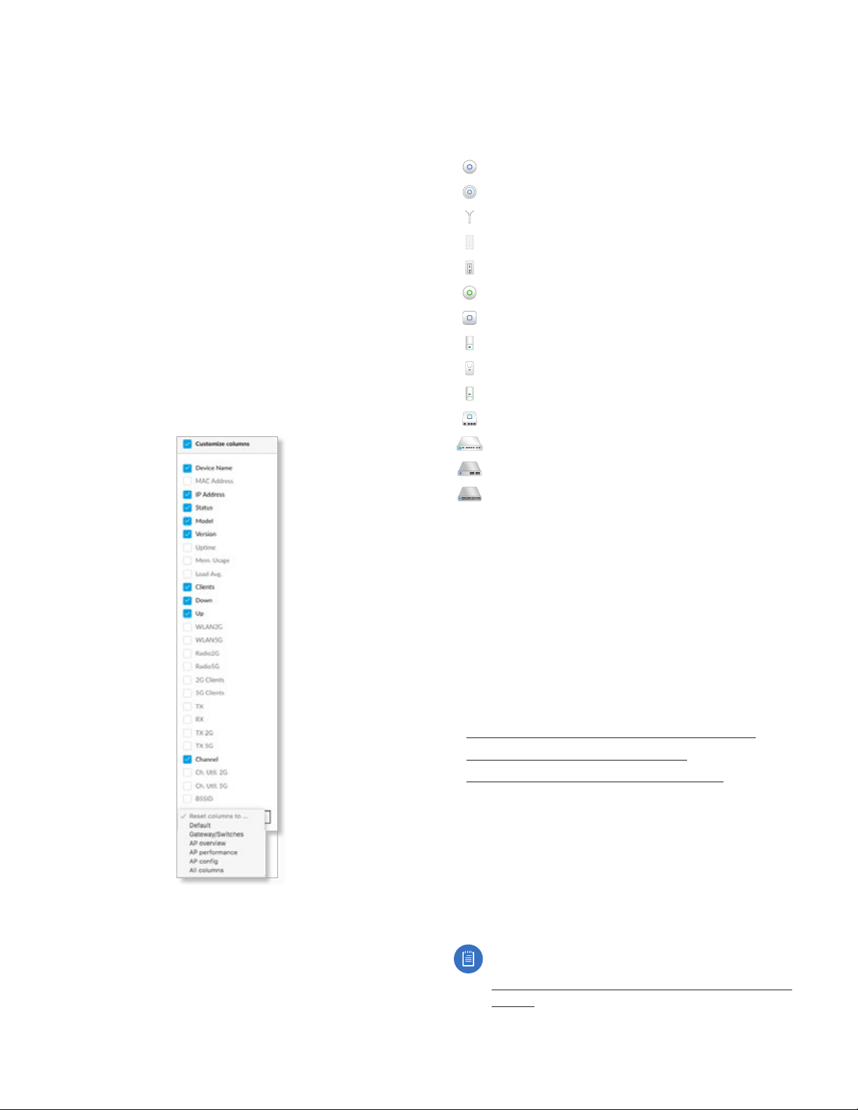
UniFi Controller User Guide
Chapter 7: Devices
• Default The Device Name, IP Address, Status, Model,
Version, Uptime, and Actions columns are displayed.
• Gateway/Switches The Device Name, IP Address,
Status, Model, Version, Down, Up, and Actions
columns are displayed.
• AP Overview The Device Name, IP Address, Status,
Model, Version, Clients, Down, Up, Channel and
Actions columns are displayed.
• AP Performance The Device Name, IP Address,
Status, 2G Clients, 5G Clients, TX, RX, TX 2G, TX 5G,
Channel, and Actions columns are displayed.
• AP Config The Device Name, Status, Version,
WLAN2G, WLAN5G, Radio2G, Radio5G, and Actions
columns are displayed.
• All columns The Device Name, MAC Address, IP
Address, Status, Model, Version, Uptime, Mem. Usage,
Load Avg., Clients, Down, Up, WLAN2G, WLAN5G,
Radio2G, Radio5G, 2G Clients, 5G Clients, TX, RX,
TX2G, TX 5G, Channel, Ch. Util. 2G, Ch. Util. 5G, BSSID,
and Actions
columns are displayed.
All
All UniFi device types are displayed.
(icon) Displays the icon corresponding to the UniFi device
(not all icons are shown below):
UniFi AP Pro, UniFi AP AC Lite/LR/Pro/HD/SHD
UniFi AP AC EDU
UniFi AP AC Mesh
UniFi AP AC Mesh Pro
UniFi AP In-Wall/AP AC In-Wall
UniFi AP/AP LR
UniFi AP AC
UniFi AP AC Outdoor
UniFi AP Outdoor+
UniFi AP Outdoor5
UniFi Security Gateway
UniFi Security Gateway Pro
UniFi 24-Port Switch
UniFi 48-Port Switch
If displayed, the LED color of the device icon indicates the
device status.
• Blue/Green Indicates the device is connected.
• Gray Indicates the device is pending approval.
• Red/Orange Indicates the device is disconnected or
not managed by this site (Pending Approval or Managed
by Other).
Device Name Displays the hostname, alias, or MAC
address of the UniFi device. You can click the name to
get additional details. For more information, see the
appropriate chapter:
• “UniFi Security Gateway Details” on page 115
• “UniFi Switch Details” on page 121
• “UniFi Access Point Details” on page 131
IP Address Displays the IP address used by the UniFi
device.
Status Indicates the device status: Connected,
Disconnected, Pending Approval, Adopting, Upgrading,
Managed by Other, or Isolated (APs only).
Only the superadmin and admins who have permission to
adopt devices can view devices that are Pending Approval
and then adopt them on the UniFi Controller.
Ubiquiti Networks, Inc.
Note: The superadmin account was created during
the initial installation; for more information, see
“Configuring the UniFi Controller Software” on
page 2.
Model Displays the model name of the UniFi device.
91
Page 98
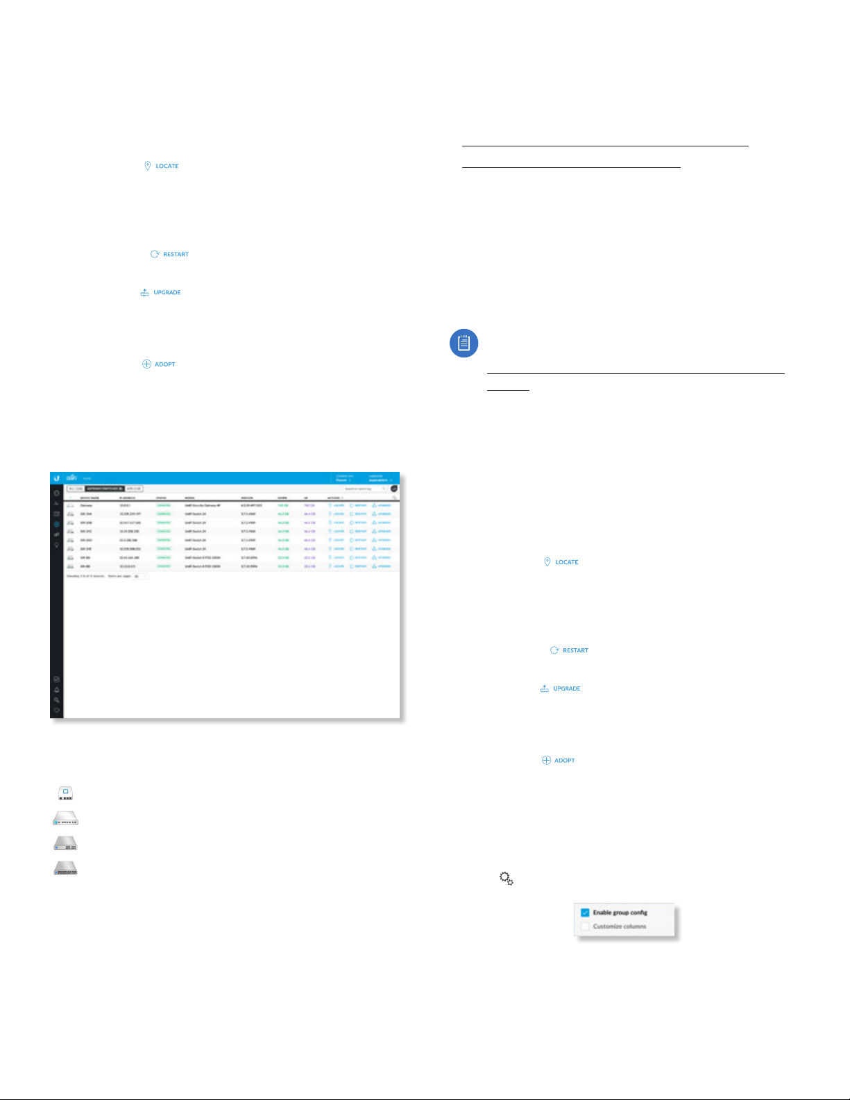
Chapter 7: Devices
UniFi Controller User Guide
Version Displays the version number of the UniFi device’s
firmware.
Uptime Displays the duration of time the UniFi device has
been running.
Actions Click a button to perform the desired action:
• Locate Click
device and the device’s icon on the Map tab so you can
locate it. The LED will flash until the Locate button is
clicked again. (The icon on the Map tab will flash three
times and stop.)
• Restart Click
• Upgrade If a software upgrade is available for the
device, click
on the device. The Status will appear as Upgrading until
the process is complete and the device reconnects to
the UniFi Controller software.
• Adopt Click
Pending Approval for its status. The Status will appear as
Adopting until the device is connected.
to flash the LED on the physical
to restart the selected device.
to install the latest UniFi firmware
to adopt a device that appears as
Gateway/Switches
All UniFi Gateway and Switch devices are displayed.
(icon) Displays the icon corresponding to the UniFi device
(not all icons are shown below):
UniFi Security Gateway
Device Name Displays the hostname, alias, or MAC
address of the UniFi device. You can click the name to
get additional details. For more information, see the
appropriate chapter:
• “UniFi Security Gateway Details” on page 115
• “UniFi Switch Details” on page 121
IP Address Displays the IP address used by the UniFi
device.
Status Indicates the device status: Connected,
Disconnected, Pending Approval, Adopting, Upgrading, or
Managed by Other.
Only the superadmin and admins who have permission to
adopt devices can view devices that are Pending Approval
and then adopt them on the UniFi Controller.
Note: The superadmin account was created during
the initial installation; for more information, see
“Configuring the UniFi Controller Software” on
page 2
Model Displays the model name of the UniFi device.
Version Displays the version number of the UniFi device’s
firmware.
Down Displays in green the total amount of data
downloaded by the UniFi device.
Up Displays in purple the total amount of data uploaded
by theUniFi device.
Actions Click a button to perform the desired action:
• Locate Click
Gateway/Switch and its icon on the Map tab so you can
locate it. The LED will flash until the Locate button is
clicked again. (The icon on the Map tab will flash three
times and stop.)
• Restart Click
• Upgrade If a software upgrade is available for the
device, click
on the device. The Status will appear as Upgrading until
the process is complete and the device reconnects to
the UniFi Controller software.
• Adopt Click
Pending Approval
Adopting until the device is connected.
.
to flash the Status LED on the
to restart the selected device.
to install the latest UniFi firmware
to adopt a device that appears as
for its status. The Status will appear as
UniFi Security Gateway Pro
UniFi 24-Port Switch
UniFi 48-Port Switch
The LED color of the device icon indicates the device
status.
• Green Indicates the device is connected.
• Gray Indicates the device is pending approval.
• Red Indicates the device is disconnected or not
managed by this site (Pending Approval or Managed by
Other).
92
Group Configuration
To enable group or batch configuration, follow these
instructions:
1. Click and then select Enable group config.
2. Select the appropriate switches.
Ubiquiti Networks, Inc.
Page 99
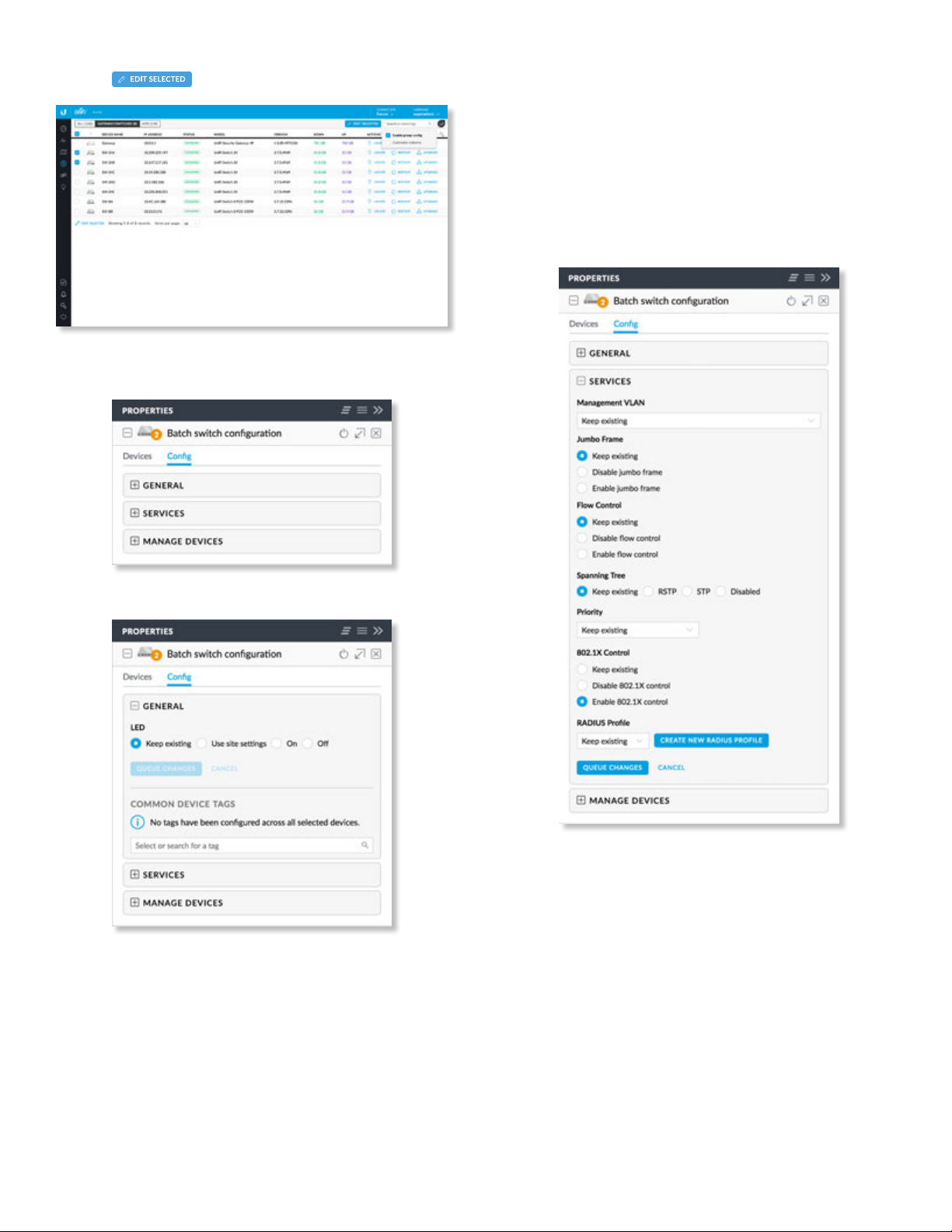
UniFi Controller User Guide
Chapter 7: Devices
3. Click .
4. The Properties panel opens. Click the + icon to expand
the appropriate section:
When you are done with your changes, click Apply
Changes at the bottom of the screen. (You can
cancel the changes of any section by clicking X of
the appropriate section.)
• Cancel Click Cancel to discard changes.
• Common Device Tags Select or search for a device
tag. You can also enter a keyword and press Enter to
save a new device tag.
6. In the Services section, make the appropriate changes:
5. In the General section, make the appropriate change:
• LED Select Keep existing (behavior), Use site
settings, On, or Off.
• Queue Changes Click Queue Changes to line up
the changes to take effect. This allows you to make
multiple changes to the device and then apply
them all at once so that the device doesn’t have to
re-provision over and over again when you change
different sections of the configuration. Each section
with pending changes is highlighted by an ellipsis.
• Management VLAN The Management VLAN
specifies the VLAN ID that will be used for the
management IP address of the switch. The IP
configuration configured under the switch’s Network
panel will be applied to this VLAN ID. The default is
Keep existing (setting).
• Jumbo Frame The Maximum Transmission Unit
(MTU) is the maximum packet size (in bytes) that
a network interface can transmit or receive. The
standard Ethernet MTU is 1500 bytes. Enable jumbo
frames to allow usage of MTUs up to 9216 bytes on
all ports of this switch. The default is Keep existing
(setting).
Ubiquiti Networks, Inc.
93
Page 100
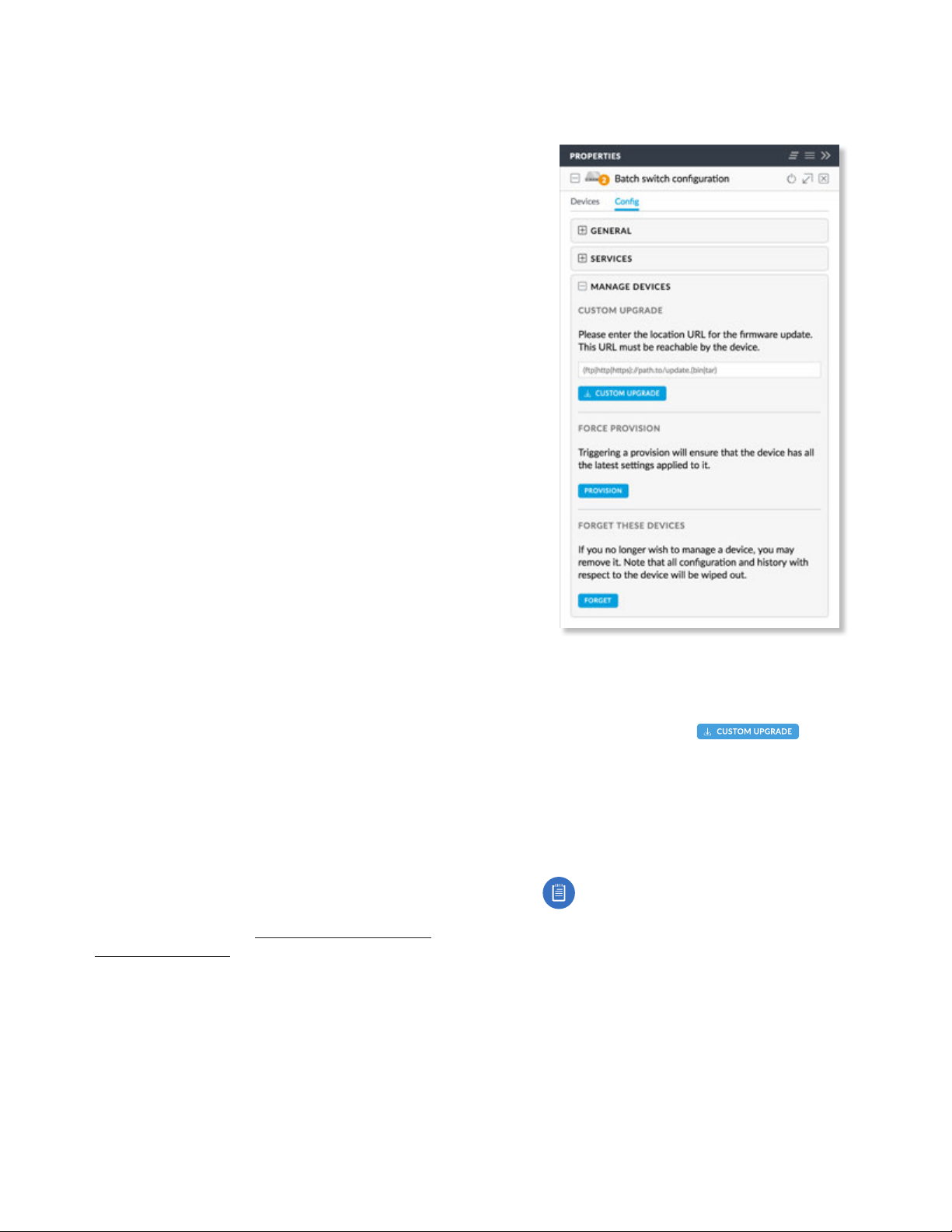
Chapter 7: Devices
UniFi Controller User Guide
• Flow Control Enabling this option will enable
802.3x Ethernet Flow Control on all ports of this
switch. This should remain disabled, unless you have
a specific requirement for 802.3x and understand its
implications. The default is Keep existing (setting).
• Spanning Tree Ethernet networks cannot have
multiple active paths between switches (absent
aggregation such as LAG), as this causes a switching
loop, where broadcast and multicast traffic are
amplified and repeated in a never-ending loop.
Spanning Tree prevents switching loops, and allows
for redundant interconnections between switches.
Interfaces with redundant paths are put into STP
blocking mode, leaving the port down unless the
current best active path fails.
Select the appropriate option: RSTP (Rapid
Spanning Tree Protocol), STP (Spanning Tree
Protocol), or Disabled. RSTP is the default and is
recommended because topology changes apply
much more quickly (usually within 6 seconds, rather
than the 30-50 seconds of STP). STP will enable the
older 802.1D STP on this switch instead of RSTP.
Disabled will disable all versions of spanning tree;
however, this is not recommended, as it can leave
the network susceptible to being taken down by an
inadvertently created switching loop. The default is
Keep existing (setting).
• Priority STP uses the priority value as part of the
calculation in electing a root bridge of the spanning
tree. It is best to configure a lower priority number
(higher preference in root bridge elections) on one
or two of the switches you consider the “core” of
your network. For instance, if you have two 10Gb
switches, and several gigabit switches, configure a
lower priority on the two 10Gb switches to ensure
that they are preferred as the STP root bridge. The
default is Keep existing (setting).
• 802.1x Control Select this option to use a RADIUS
server for user authentication on the switch’s ports.
The default is Keep existing (setting).
If you enable 802.1X control, then the RADIUS Profile
setting appears.
• RADIUS Profile The default is Keep existing (setting).
You can click Create New RADIUS Profile to create
a new one to use. Go to “Create or Edit a RADIUS
Profile” on page 45 for instructions.
• Queue Changes Click Queue Changes to line up
the changes to take effect. This allows you to make
multiple changes to the device and then apply
them all at once so that the device doesn’t have to
re-provision over and over again when you change
different sections of the configuration. Each section
with pending changes is highlighted by an ellipsis.
When you are done with your changes, click Apply
Changes at the bottom of the screen. (You can
cancel the changes of any section by clicking X of
the appropriate section.)
94
• Cancel Click Cancel to discard changes.
7. In the Manage Devices section, make the appropriate
changes:
• Custom Upgrade For firmware upgrades, the
UniFi devices retrieve the latest firmware from the
Ubiquiti website. To specify firmware saved in a
custom location, enter the URL of the firmware’s
location and then click
the firmware.
• Force Provision Click Provision to ensure that the
device has all of the latest settings applied to it.
• Forget These Devices Click Forget to remove the
Switches from management by the UniFi Controller
software and reset them to factory default settings.
Note: Use caution when clicking Forget. This
will restore the Switches to factory default
settings when they are in a Connected state.
8. Click the Devices tab to view the selected Switches.
Ubiquiti Networks, Inc.
to upgrade
 Loading...