


24 GHz Full Duplex
Point-to-Point 2 Gbps Radio
Model: AF-24HD

Introduction
Introduction
Thank you for purchasing the Ubiquiti Networks® airFiber® 24 GHz Full Duplex Point-to-Point 2 Gbps Radio. This Quick Start Guide
is designed to guide you through installation, show you how to access the airFiber Configuration Interface, and explain how to set up an airFiber link. This Quick Start Guide also includes the warranty terms and is for use with the model AF-24HD.
Package Contents
|
|
|
|
|
airFiber AF-24HD |
Pole Mount Bracket |
Pole Clamps |
GPS Antenna |
|
|
|
|
(Qty. 2) |
Mount |
Carriage Bolts |
Flat Washers |
Split Lock |
Hex Nuts |
Metal Strap |
(M10x150, Qty. 4) |
(M10, Qty. 4) |
Washers |
(M10, Qty. 4) |
|
|
|
(M10, Qty. 4) |
|
|
External GPS |
Cable Ties |
Gigabit PoE |
Power Cord |
Quick Start |
Antenna |
(Qty. 3) |
Adapter |
|
Guide |
|
|
(50V, 1.2A) |
|
|
TERMS OF USE: Ubiquiti radio devices must be professionally installed. Shielded Ethernet cable and earth grounding must be used as conditions of product warranty. TOUGHCable™ is designed for outdoor installations. It is the customer’s responsibility to follow local country regulations, including operation within legal frequency channels, output power, and Dynamic Frequency Selection (DFS) requirements.
1
airFiber® AF-24HD Quick Start Guide
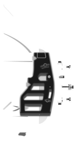
Hardware Overview
Side
10
5
0
5
Lock Bolts

 Alignment Bracket
Elevation
Adjustment
Azimuth
Adjustment
Lock Bolts
Ground
Bonding Point
2
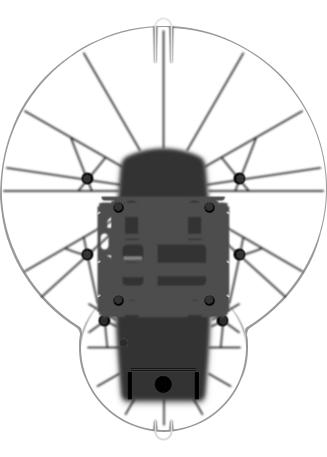
Hardware Overview
Back
Lanyard Loop
Lock Bolts |
Lock Bolts |
Elevation |
Azimuth |
Adjustment |
Adjustment |
Lock Bolts |
Lock Bolts |
Port Cover |
Cover Lock |
Lanyard Loop |
|
3
airFiber® AF-24HD Quick Start Guide
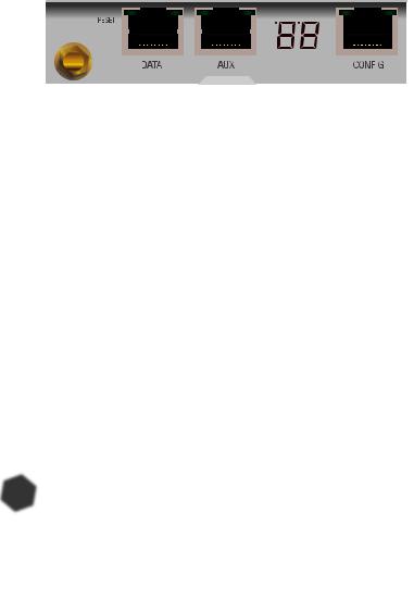
Interfaces
|
GPS RESET |
DATA |
AUX |
LED Display |
|
CONFIG |
||||||||||
|
|
|
|
|
|
|
|
|
|
|
|
|
|
|
|
|
|
|
|
|
|
|
|
|
|
|
|
|
|
|
|
|
|
|
|
|
|
|
|
|
|
|
|
|
|
|
|
|
|
|
|
|
|
|
|
|
|
|
|
|
|
|
|
|
|
|
|
|
|
|
|
|
|
|
|
|
|
|
|
|
|
|
|
|
|
|
|
|
|
|
|
|
|
|
|
|
|
|
|
|
|
|
|
|
|
|
|
|
|
|
|
|
|
|
|
|
|
|
|
|
|
|
|
|
|
|
|
|
|
|
|
|
|
|
|
|
|
|
|
|
|
|
|
|
|
|
|
|
|
|
|
|
|
|
|
|
|
|
|
|
|
|
|
|
|
|
|
|
|
Interface |
Description |
|
|
GPS |
Connect the External GPS Antenna to this SMA connector. |
|
To reset to factory defaults, press and hold the Reset |
RESET |
button for more than five seconds while the unit is |
|
already powered on. |
DATA |
10/100/1000 Mbps port handles all user traffic. |
AUX |
Port for audio tone aiming. |
LED Display |
Digital display used for power, status, and mode |
information. |
|
|
10/100 Mbps, secured port for configuration. By default, |
CONFIG |
this is the only port that can monitor, configure, and/or |
|
update firmware. |
|
|
LEDs
Speed |
GPS |
RX Power |
Speed |
||||||||||
|
Link/Act |
|
Modulation |
|
|
|
|
|
Link/Act |
||||
|
|
|
|
|
|
|
|||||||
|
|
|
|
|
|
|
|
|
|
|
|
|
|
|
|
|
|
|
|
|
|
|
|
|
|
|
|
|
|
|
|
|
|
|
|
|
|
|
|
|
|
|
|
|
|
|
|
|
|
|
|
|
|
|
|
|
|
|
|
|
|
|
|
|
|
|
|
|
|
|
|
|
|
|
|
|
|
|
|
|
|
|
|
|
|
|
|
|
|
|
|
|
|
|
|
|
|
|
|
|
|
|
|
|
|
|
|
|
|
|
|
|
|
|
|
|
|
|
|
|
|
|
|
|
|
Master/Slave |
|
|
|
RF Link Status |
|
|
4

Hardware Overview
DATA
AUX
LED Display
CONFIG
LED |
|
State |
|
Status |
|
|
Speed |
|
Off |
|
10/100 Mbps |
|
|
|
|||
|
|
|
|
|
|
|
|
On |
|
1000 Mbps |
|
|
|
|
|
||
|
|
|
|
|
|
|
|
|
Off |
|
No Ethernet Link |
|
|
|
|
|
|
|
Link/Act |
|
On |
|
Ethernet Link Established |
|
|
|
|
|
|
|
|
|
Random Flashing |
|
Ethernet Activity |
|
|
|
Off |
|
No GPS Synchronization |
|
|
|
|
||
|
|
|
|
|
|
|
GPS |
|
On |
|
Operational (Strong Signal) |
|
|
|
|
|
|
|
|
|
Normal Flash* |
|
Operational (Weak Signal) |
|
|
|
|
|
|
|
|
|
Off |
|
¼x or 1x (QPSK SISO) |
|
|
|
|
|
|
|
|
|
Short Flash* |
|
2x (QPSK MIMO) |
|
|
|
|
|
|
|
Modulation |
|
Normal Flash* |
|
4x (16QAM MIMO) |
|
|
|
|
|
|
|
|
|
Long Flash* |
|
6x (64QAM MIMO) |
|
|
|
|
|
|
|
|
|
On |
|
8x (256QAM MIMO) |
|
|
|
Number |
|
Decodable RX Signal |
|
|
|
|
||
|
RX Power |
|
|
|
|
|
|
Flashing Number |
|
Undecodable RX Signal |
|
|
(-dBm) |
|
|
|
|
|
|
|
|
Overload Condition |
|
|
|
|
|
|
|
|
|
|
|
|
|
|
Master/ |
|
Off |
|
Slave Mode |
|
Slave |
|
On |
|
Master Mode |
|
|
|
|
|
|
|
|
|
Off |
|
RF Off |
|
|
|
|
|
|
|
|
|
Short Flash* |
|
Syncing |
|
RF Link |
|
|
|
|
|
|
Normal Flash* |
|
Beaconing |
|
|
Status |
|
|
||
|
|
Long Flash* |
|
Registering |
|
|
|
|
|
||
|
|
|
|
|
|
|
|
|
On |
|
Operational |
|
Speed |
|
Off |
|
10 Mbps |
|
|
|
|||
|
|
|
|
|
|
|
|
On |
|
100 Mbps |
|
|
|
|
|
||
|
|
|
|
|
|
|
|
|
Off |
|
No Ethernet Link |
|
|
|
|
|
|
|
Link/Act |
|
On |
|
Ethernet Link Established |
|
|
|
|
|
|
|
|
|
Random Flashing |
|
Ethernet Activity |
|
|
|
|
|
|
* Short Flash (1:3 on/off cycle) Normal Flash (1:1 on/off cycle)
Long Flash (3:1 on/off cycle)
5

airFiber® AF-24HD Quick Start Guide
Installation Requirements
•17 mm wrench
•13 mm socket wrench or driver
•Clear line of sight between airFiber radios
•Clear view of the sky for proper GPS operation
•Mounting location with < 0.5° displacement due to twist and sway under wind loading
•Mounting point:
•At least 1 meter below the highest point on the structure
•For tower installations, at least 3 meters below the top of the tower
•Ground wires – min. 8 AWG (10 mm2) and max. length: 1 meter.
As a safety precaution, ground the airFiber radios to grounded masts, poles, towers, or grounding bars.
WARNING: Failure to properly ground your airFiber units will void your warranty.
•(Recommended) 2 Outdoor Gigabit PoE surge protectors – Ubiquiti Ethernet Surge Protector, model ETH-SP.
Note: For guidelines about grounding and lightning protection, follow your local electrical regulatory codes.
•Outdoor, shielded Category 5e (or above) cabling and shielded RJ-45 connectors should be used for all wired Ethernet connections. Category 6 is required for installations with long cable runs (up to 100 m).
We recommend that you protect your networks from the most brutal environments and devastating ESD attacks with industrial grade shielded Ethernet cable and shielded RJ-45 connectors from Ubiquiti Networks. For more details, visit www.ubnt.com/toughcable
6
Installation Overview
Installation Overview
We recommend that you configure your paired airFiber radios before mounting. Below is an overview of the installation with specific details on the following pages:
•Connect Power over Ethernet to the DATA port, and connect an Ethernet cable between your computer and the CONFIG port.
•Configure device settings in the airFiber Configuration Interface.
•Once configuration is complete, disconnect the cables to move the airFiber radios.
•Reconnect at the site.
•After you have mounted the airFiber radios, establish and optimize the RF link.
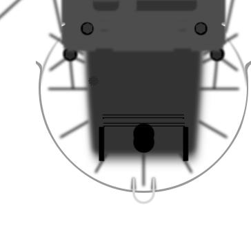
Connecting Power over Ethernet
1.Turn the Cover Lock to the Unlocked  icon. Slide the Port Cover down to remove it.
7

airFiber® AF-24HD Quick Start Guide
2. Connect an Ethernet cable to the DATA port.
3.Connect the other end of the Ethernet cable from the DATA port to the Ethernet port labeled POE on the Gigabit PoE Adapter.
4.Connect the Power Cord to the power port on the Gigabit PoE Adapter. Connect the other end of the Power Cord to a power source.
8
airFiber Configuration
airFiber Configuration
The instructions in this section explain how to access the airFiber
Configuration Interface and configure the following settings:
•Wireless Mode Configure one airFiber AF-24HD as the Master and the other as the Slave.
•Duplex The airFiber AF-24HD supports both half-duplex and full duplex operation. Half-duplex operation provides more frequency planning options at the cost of higher latency and throughput. Full-duplex operation provides the highest throughput and lowest latency; however, you have fewer frequency management options.
-- Half Duplex (default) The TX and RX Frequencies can be the same or different to suit local interference.
RX |
RX |
A
Frequency
TX
Frequency A
TX
Master |
Slave |
Half-Duplex Diagram
-- Full Duplex The TX and RX Frequencies should be different.
RX |
RX |
A
Frequency
TX
Master
Full-Duplex Diagram
Frequency B
TX
Slave
•TX and RX Frequencies The TX Frequency on the Master must match the RX Frequency on the Slave, and vice versa.
9

airFiber® AF-24HD Quick Start Guide
1.Connect an Ethernet cable from your computer to the CONFIG port on the airFiber AF-24HD.
2.Configure the Ethernet adapter on your computer with a static IP address on the 192.168.1.x subnet (for example, 192.168.1.100).
3.Launch your web browser. Type http://192.168.1.20 in the address field and press enter (PC) or return (Mac).
4.The login screen will appear. Enter ubnt in the Username and Password fields. Select your Country and Language. You must agree to the Terms of Use to use the product. Click Login.
Note: U.S. product versions are locked to the U.S. Country Code to ensure compliance with FCC regulations.
10
 Loading...