


Model: UCK-G2-PLUS
Table of Contents
Introduction |
3 |
Hardware Overview |
5 |
Hardware Installation |
10 |
Powering the Cloud Key Gen2 Plus |
11 |
Optional Rackmount Accessory |
12 |
Setting Up UniFi SDN via App |
14 |
Pre-installed Software |
19 |
Setting Up UniFi Protect via App |
20 |
Chrome Instructions |
26 |
Setting Up UniFi SDN |
27 |
Setting Up UniFi Protect |
31 |
Cloud Key G2+ Settings |
36 |
HDD Replacement |
38 |
Specifications |
40 |
Safety Notices |
41 |
Electrical Safety Information |
41 |
Limited Warranty |
41 |
Compliance |
44 |
Declaration of Conformity |
48 |
2

Introduction
Thank you for purchasing the Ubiquiti Networks® UniFi® Cloud Key Gen2 Plus. This Quick Start Guide is designed to guide you through installation and also includes warranty terms.
Package Contents
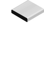
UniFi Cloud Key Gen2 Plus
System Requirement
Web Browser: Google Chrome (Other browsers may have limited functionality.)
TERMS OF USE: All Ethernet cabling runs must use CAT5 (or above). It is the professional installer’s responsibility to follow local country regulations, including operation within legal frequency channels, output power, indoor cabling requirements, and Dynamic Frequency Selection (DFS) requirements.
3
Network Topology
A DHCP-enabled network (for the Cloud Key Gen 2 Plus to obtain an IP address)
UniFi Cloud Key Gen2 Plus
UniFi PoE Switch
LAN
|
|
|
|
|
|
|
|
|
|
|
|
|
|
|
|
UniFi Security Gateway |
WAN |
|
|
|
|
|
|
|
|
||||||
(DHCP Server) |
|
|
|
|
|
|
|
|
|
|
|
|
|||
Internet
Sample Network Diagram
4
Hardware Overview
Front Panel LED
|
|
|
|
LED |
|
|
|
|
|
|
|
|
||
Color |
State |
Status |
||
White |
Solid |
Device is ready to be configured |
||
|
|
|
||
|
Flashing |
Device is booting up |
||
|
|
Device is initializing/deinitializing |
||
|
Heartbeat |
Firmware update in process |
||
Blue |
Solid |
Device is configured and ready |
||
|
Flashing |
Main power has been lost and |
||
|
|
device is counting down. |
||
|
|
If power is restored within 10 |
||
|
|
seconds, the device will return to |
||
|
|
its previous state. If power is not |
||
|
|
restored within 10 seconds, the |
||
|
|
device will safely shutdown. |
||
|
Slow |
Client connected to device via |
||
|
Flashing |
Bluetooth (BLE) |
||
Off/White/ |
Flashing |
Device is in recovery mode. |
||
Blue |
|
The LED will cycle through a |
||
|
|
|||
|
|
pattern at one second intervals, |
||
|
|
between off, white, and blue. |
||
5

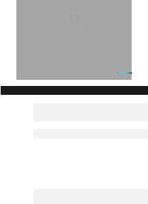
Front Panel
HDD |
|
|
|
|
LCD |
||
Bay |
|
|
|
|
|
|
Screen |
|
|
|
|
|
|
|
|
HDD Bay Removable hard drive tray for 2.5" SATA drive
LCD Screen Device Status display. Automatically rotates status screens for enabled controllers
|
|
|
|
UniFi SDN Display |
UniFi Protect Display |
LCD Display for UniFi SDN |
|
||||
|
|
|
|
|
|
Icon |
Description |
|
|||
|
|
|
|
UniFi SDN Controller name |
|
|
|
|
|
|
|
|
|
|
|
|
|
|
|
|
|
Current WAN bandwidth usage |
|
|
|
|
|
|
|
|
|
|
|
Status of SDN Cloud Access |
|
|
|
|
|
|
|
|
|
|
|
Number of managed UniFi Access Points |
|
|
|
|
|
|
|
|
|
|
|
Number of client devices on the network |
|
|
|
|
|
|
|
LCD Display for UniFi Protect |
|
||||
|
|
|
|
|
|
Icon |
Description |
|
|||
|
|
|
|
UniFi Protect Controller name and bandwidth |
|
|
|
|
|
|
|
|
|
|
|
Total camera(s) recording bitrate |
|
|
|
|
|
|
|
|
|
|
|
Status of Protect Cloud Access |
|
|
|
|
|
|
|
|
|
|
|
Number of active cameras registered in UniFi Protect |
|
|
|
|
|
Time of last motion detected by UniFi Protect |
|
|
|
|
|
||
|
|
|
|
|
|
6
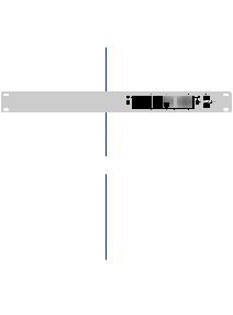
Back Panel
|
|
Reset |
|
microSD |
USB Type C |
|||||||
|
Button |
|
|
Slot |
Port |
|||||||
Power |
|
|
|
|
|
|
|
|
|
|||
|
|
|
|
|
|
|
|
|
||||
Button |
|
|
|
|
|
|
|
|||||
|
|
|
|
|
|
|
|
|
|
|
|
|
USB Type C |
|
|
|
|
Ethernet |
|
|
|||||
Power Port |
|
|
|
Port |
|
|
||||||
Reset The Reset button serves two functions:
•Restart Press and release the Reset button quickly.
•Restore to Factory Default Settings Press and hold the
Reset button for more than five seconds, until the status LED begins flashing white.
Power Button Press to turn the Cloud Key Gen 2 Plus on or off.
USB Type C Power Port Used for power if PoE is not available. Quick Charge 2.0 or Quick Charge 3.0-compliant USB power adapter is required.
microSD Slot Optional slot used for external backup (microSD card not included).
Ethernet Port Connects to a gigabit switch port on your LAN. Power can be provided by an 802.3af PoE switch, such as the UniFi PoE Switch.
USB Type C Port Reserved for future use.
7
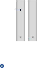
Side Panels
Security
Slot
Rack-Mount |
|
|
|
Rack-Mount |
Notch |
|
|
|
Notch |
Security Slot Allows the Cloud Key Gen 2 Plus to be used with a Kensington security lock (not included). When used, it also prevents removal of the HDD while the device is in use.
Rack-Mount Notch Secures the Cloud Key Gen2 Plus into the docking bay of the optional Rackmount Accessory, model CKG2-RM (sold separately). The Rackmount Accessory allows you to install the Cloud Key Gen2 Plus in a standard 19" rack.
Note: The Rackmount Accessory is completely optional and not required for the Cloud Key Gen2 Plus to function.
8
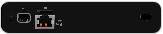
Bottom Panel
|
|
|
|
|
|
|
|
|
|
|
|
|
|
|
|
|
|
13-Pin Connector |
HDD Latch |
||||
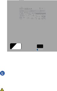
13-Pin Connector Connects the Cloud Key Gen2 Plus to the optional Rackmount Accessory, model CKG2-RM (sold separately). The CKG2-RM has a docking bay for the Cloud Key Gen2 Plus and allows you to install it in a standard 19" rack.
Note: Out of the box, the 13-Pin Connector is covered with a black sticker to protect it from dust and dirt. Only remove the sticker if using the Cloud Key Gen2 Plus with the optional Rackmount Accessory.
HDD Latch Releases the HDD tray from the drive bay.
WARNING: Do not operate the HDD Latch while the Cloud Key Gen2 Plus is in use or powered on.
9
Hardware Installation
1.Connect an Ethernet cable (not included) to the
Ethernet Port.
2.Connect the other end of the Ethernet cable to a port on a network switch, such as a UniFi PoE Switch.
1 |
|
|
|
|
3 |
|
|
|
|
|
5 |
|
|
|
|
7 |
|
|
|
2 |
9 |
|
|
|
4 |
11 |
|
|
|
|
6 |
13 |
|
|
|
8 |
15 |
|
|
|
10 |
|
17 |
|
|
12 |
|
19 |
|
|
|
14 |
21 |
|
|
|
16 |
|
22 |
|
|
|
18 |
|
|
|
|
20 |
SFP1 |
|
|
|
22 |
|
|
|
|
|
24 |
|
|
|
|
SFP2 |
10
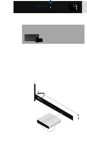
Powering the Cloud Key Gen2 Plus
Use an 802.3af-compliant switch, such as a UniFi PoE Switch, a USB power source, or 48V PoE adapter (not included).
UniFi Switch
The Cloud Key Gen 2 Plus can be powered by a UniFi PoE Switch or other 802.3af-compliant switch.
|
15 |
|
|
|
17 |
|
|
19 |
|
|
21 |
|
16 |
22 |
|
|
18 |
1 |
|
20 |
3 |
|
22 |
5 |
|
24 |
|
7 |
|
2 |
9 |
|
4 |
11 |
|
6 |
13 |
|
|
8 |
|
|
10 |
|
|
12 |
|
|
14 |
|
SFP1
SFP2
UniFi Switch Power Connection Diagram
USB Power Source
Connect a USB cable (not included) from the Cloud Key Gen 2 Plus directly to a USB power source: Quick Charge 2.0 or Quick Charge 3.0 compliance is required.
USB Power Connection Diagram
11

Optional Rackmount Accessory
There is an optional UniFi Rackmount Accessory (sold separately) that can mount the Cloud Key Gen2 Plus in a standard 19" rack.
Lock Tab
Docking
Bay
To install the Rackmount Accessory, follow these instructions:
1.Attach the Rackmount Accessory to the rack using four Mounting Screws. (If the rack has square slots, then use
Cage Nuts with the Mounting Screws.)
2.Connect an Ethernet cable (not included) to the Ethernet Port on the front of the Rackmount Accessory.
3.Connect the other end of the Ethernet cable to a port on a compatible PoE switch, such as a UniFi PoE Switch.
12
When connecting the Cloud Key Gen2 Plus to the Rackmount Accessory, the width of the Docking Bay must be adjusted to accommodate the dimensions. To adjust the Docking Bay:
1.Press down on the Lock Tab and slide the docking bay cover open until it locks into place.
2.Remove the pre-installed sticker from the 13-pin connector.
3.Insert the Cloud Key Gen2 Plus into the docking bay once the following three conditions are met:
a.The 13-pin connector is face up
b.The LCD screen is face forward
c.There is no Ethernet cable connected to the Ethernet Port on the Cloud Key Gen2 Plus
Warning: To prevent creating a loop or other unfavorable behavior on the network, only one Ethernet connection should be used. Do not use the Ethernet port on the Cloud Key Gen2 Plus and
the Rackmount Accessory simultaneously.
13
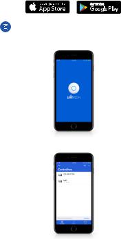
Setting Up UniFi SDN via App
Download and install the UniFi SDN app to configure the Cloud Key Gen2 Plus.
Note: Ensure that Bluetooth is enabled on your mobile device. You will need to set up the Cloud Key Gen2 Plus with your mobile device and be within 1.5 m (5’) from where it is installed.
1. Launch the app and tap the + icon to add a new controller.
14
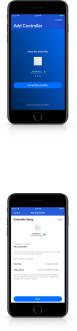
2.Once detected, the app will automatically connect to the Cloud Key Gen2 Plus and the LED will begin to flash blue. If more than one controller is detected, swipe through the app screens horizontally until you locate the correct Cloud Key Gen2 Plus. Then tap Set up this controller.
3.Once connected, the corresponding Controller Setup screen will appear. Enter a name for the UniFi SDN controller
and select the appropriate Country and Time Zone information. When you are finished, tap Next.
15
 Loading...