


Optical Data Transport for Outdoor PoE Devices
Model: F-POE-G2

Introduction
Thank you for purchasing the Ubiquiti Networks® FiberPoE™ Gen 2. This Quick Start Guide is designed to guide you through installation and also includes warranty terms.
Package Contents
FiberPoE Gen 2 |
Self-Tapping |
Metal Straps |
|
Screw |
(Qty. 2) |
Installation Requirements
Mounting accessories and drain wire are not included. Pole-Mounting
•Drill with a 4.5 mm Drill Bit
•7 mm Socket Wrench or Screwdriver
Wall-Mounting
•(2) Screws (≤ 5 mm Screw Head)
•(1) Drain Wire, Optional (≤ 16 AWG, ≤ 40 cm)
Cables
•Shielded Category 5 (or above) cabling with drain wire should be used for all wired Ethernet connections and should be grounded through the AC ground of the PoE.
We recommend that you protect your networks from harmful outdoor environments and destructive ESD events with industrial grade, shielded Ethernet cable from Ubiquiti Networks. For more details, visit www.ubnt.com/toughcable
Surge Protection
•Surge protection should be used for all outdoor installations. We recommend that you use two Ethernet Surge Protectors, model ETH-SP, one near the FiberPoE and the other at the entry point to the building. The ETH-SP will absorb power surges and safely discharge them into the ground.
TERMS OF USE: Shielded Ethernet cable and earth grounding must be used as conditions of product warranty. TOUGHCable™ is designed for outdoor installations. It is the professional installer’s responsibility to follow local country regulations, including operation within legal frequency channels, output power, and Dynamic Frequency Selection (DFS) requirements.

Application Examples
The following are typical use cases for the FiberPoE.
Data Options
Fiber Bridge Two FiberPoE devices, one at the base and one at the top of the tower, are used to provide a fiber optic data link for protection from EMI events that can cause equipment damage or signal integrity issues.
Ethernet-to-Fiber Converter One FiberPoE at the top of the tower is used to convert Ethernet to fiber at the radio.
|
|
Fiber Bridge |
|
|
Ethernet-to-Fiber |
||||||||||||
|
|
|
|
|
|
|
|
|
|
|
Converter |
||||||
Top of |
|
|
|
ETH-SP |
|
|
|
|
|
|
|
|
|||||
Tower |
|
|
|
|
|
|
|
|
|
|
|
||||||
|
|
|
|
|
|
|
|||||||||||
|
|
|
|
|
|
|
|
|
|
||||||||
|
|
FiberPOE |
|
|
|
|
Ethernet Data |
|
|
|
|
|
|
FiberPOE |
|||
|
|
|
|
|
|
|
|
||||||||||
|
|
|
|
|
|
|
|
|
|
||||||||
|
|
|
|
|
|
|
|
|
|||||||||
Fiber Optic
Data Link
FiberPOE 
Base of
Tower


 Ethernet Data
|
|
|
|
|
|
Ethernet |
Fiber |
|
|||
Switch/Router |
Switch/Router |
|
|||

Power Options
On the tower, the FiberPoE can provide PoE power to the radio. Options for providing power to the FiberPoE include:
DC Power Connect a DC power cable to the FiberPoE DC terminal block.
PoE Power Connect a PoE adapter (power only) to the FiberPoE RJ45 port.
DC Power |
PoE Power |
PoE |
ETH-SP |
PoE |
|
||
FiberPOE |
DC Terminal Block |
FiberPOE |
|
|
RJ45 DC IN Port |
|
DC Power Cable |
Ethernet Cable |
|
|
(Power Only) |
|
|
|
|
|
|
|
|
|
|
|
|
DC Power Source |
PoE Source |
||
Hardware Overview
LED
LED
Port Cover
LED Color |
Status |
White |
Power on |
|
|
Blue |
Link operational |
|
|
Flashing Blue |
Link activity |
|
|
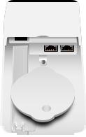
Ports |
|
Terminal Block |
DC In |
SFP |
PoE |
Ground Bonding Point with an M5 Machine Screw and Nut
SFP This hot-swappable SFP port supports a 1 Gbps link. The adjacent fiber interface must use autonegotiation; manually setting it to 1000 Mbps/1 Gbps will not allow the link to come up.
VDC Labeled (+) (–), the VDC Terminal Block provides input or output power (see the Power Configuration section for details).
DC In This RJ45 port is only used to supply DC input power.
PoE This RJ45 port provides 1 Gbps data and Power over Ethernet (PoE) passthrough, and can also be used to supply input power (see the Power Configuration section for details).
Ground Bonding Point The FiberPoE must be grounded in one of the following ways:
•Use the Self-Tapping Screw to ground the FiberPoE directly to a grounded metal pole or structure.
•Use the M5 Machine Screw and Nut to attach a drain wire (not included) that is connected to a remote grounding block or structure.

Power Configuration
There are three ways to configure the input and output power:
Input Power on Terminal Block
Input Power |
Output Power |
||||
Terminal Block, 24VDC |
PoE port, 2-pair, 24VDC |
||||
|
|
|
|
|
|
Terminal Block, 50VDC |
PoE port, 4-pair, 50VDC |
||||
|
|
|
|
|
|
|
|
|
|
|
|
|
|
|
|
|
|
|
|
|
Power In Power Out |
||
Input Power on PoE Port |
|||||
|
|
|
|
|
|
Input Power |
Output Power |
||||
PoE port, 2-pair, 24VDC |
Terminal Block, 24VDC |
||||
|
|
|
|
|
|
PoE port, 4-pair, 24VDC |
Terminal Block, 24VDC |
||||
|
|
|
|
|
|
PoE port, 4-pair, 50VDC |
Terminal Block, 50VDC |
||||
|
|
|
|
|
|
|
|
|
|
|
|
|
|
|
|
|
|
Power Out Power In
Input Power on DC In Port
Input Power |
Output Power |
||
DC In port, 2-pair, 24VDC |
Terminal Block, 24VDC |
||
PoE port, 24VDC, 2-pair |
|||
|
|||
DC In port, 4-pair, 24VDC |
Terminal Block, 24VDC |
||
PoE port, 24VDC, 4-pair |
|||
|
|||
DC In port, 4-pair, 50VDC |
Terminal Block, 50VDC |
||
|
PoE port, 50VDC, 4-pair |
||
|
|
|
|
|
Power |
|
Power |
In |
Power |
|
||
Out |
|
Out |
Note: You can use either a single power output (Terminal Block or PoE port), or both power outputs at the same time.
Note: The FiberPoE relies on the external DC power source for current-limiting protection.
Note: Input/output polarity for 2-pair PoE is pins
4, 5 (+); 7, 8 (-). Input/Output polarity for 4-pair PoE is pins 1, 2, 4, 5 (+); 3, 6, 7, 8 (-).

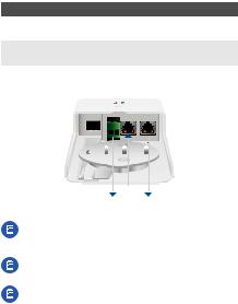
Cable Management
Feed cables through the Port Cover as indicated below. Use nippers to remove the tab over a feed hole if necessary.
Drain Wire |
|
|
|
|
|
|
DC In Cable |
DC Power Cable |
|
|
|
|
|
|
|
Fiber Cable |
|
|
|
|
|
|
PoE/Data Cable |
|
|
|
|
|
|
|
|
|
|
|
|
|
|
|
|
Connect a Drain Wire (Optional)
If a drain wire is used to ground the FiberPoE, attach it to the
Ground Bonding Point with the M5 Machine Screw and Nut.
At the installation site, secure the other end of the drain wire to a grounded mast, pole, tower, or grounding bar.
Note: The drain wire should be as short as possible and no longer than one meter in length.
 Loading...