


US-24-250W
Managed PoE+ Gigabit
Switch with SFP
Models: US-24-250W, US-24-500W
1G
Introduction
Thank you for purchasing the Ubiquiti Networks® UniFi®
Switch. This Quick Start Guide is designed to guide you
through the installation and also includes the warranty terms.
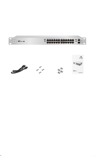
Package Contents
UniFi Switch
1G
Managed PoE+ Gigabit
Switch with SFP
Models: US-24-250W, US-24-500W
Power Cord Mounting Screws
(Qty. 4)
System Requirements
• Linux, MacOSX, or Microsoft Windows 7/8/10
• Java Runtime Environment 1.6 (1.8 or newer recommended)
• Web Browser: Mozilla Firefox, Google Chrome, Microsoft
Edge, or Microsoft Internet Explorer 11
• UniFi Controller v4.3.x or higher
TERMS OF USE: All Ethernet cabling runs must use CAT5 (or above). It is the customer’s
responsibility to follow local country regulations and indoor cabling requirements.
Cage Nuts
(Qty. 4)
Quick Start
Guide
1G
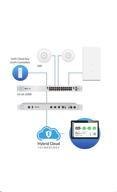
Network Topology Requirements
UAP-AC-PRO-O
(UniFi Controller)
• A DHCP-enabled network for the UniFi Switch to obtain an
IPaddress (connected devices will also obtain IP addresses
after deployment)
• A UniFi Cloud Key or management station running the UniFi
Controller software, located either on-site and connected to
the same Layer2 network, or off-site in a cloud or NOC
UniFi Cloud Key
LAN
WAN
Internet
UAP-AC-LR
1G
CURRENT SITE
Default
DASHBOARD
Network Health
MAP
DEVICES
CLIENTS
CALLS
STATISTICS
INSIGHTS
SETTINGS
Remote Access to
UniFi Controller
UAP-AC-PRO
US-24-250W
USG-PRO-4
(DHCP Server)
Sample Network Diagram
All UniFi devices support off-site management controllers.
For setup details, refer to the User Guide on the website:
documentation.ubnt.com/unifi
REFRESH RATE
2 minutes
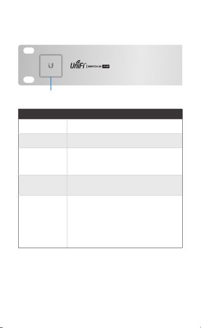
Hardware Overview
Front Panel System LED
System
State Status
White Factory defaults, waiting for integration.
Flashing White Initializing.
Alternating
White/Blue
Blue
Flashing Blue
Device is busy; do not use or unplug it.
This usually indicates that a process such
as a firmware upgrade is taking place.
Successfully integrated into a network
and working properly.
This is used to locate a device.
When you click Locate in the UniFi
Controller software, the System LED will
flash blue. The software will also display
the location of the UniFi Switch on the
map.
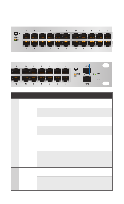
Front Panel Port LEDs
RJ45: PoE
LED State Status
Off No PoE
PoE
Amber IEEE 802.3af/802.3at
Green 24V Passive
Off No Link
RJ45 1-24
Speed/
Amber
Link/
Act
Green
Off No Link
Speed/
Link/
SFP 1-2
Act
Green
RJ45: Speed/Link/Act
SFP: Speed/Link/Act
Link Established at
10/100Mbps
Flashing Indicates Activity
Link Established at
1000Mbps
Flashing Indicates Activity
Link Established at 1Gbps
Flashing Indicates Activity
1G
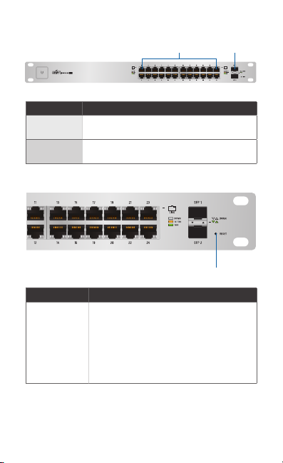
Front Panel Ports
Port Description
RJ45 1-24
SFP 1-2
RJ45 ports support Power over Ethernet (PoE)
and 10/100/1000 Ethernet connections.
Hot-swappable SFP ports support 1 Gbps
connections.
Front Panel Button
Button Description
Reset
This button serves two functions for the
UniFi Switch:
• Restart Press and release the Reset
• Restore to Factory Default
RJ45 1-24
SFP 1-2
1G
Reset
button quickly.
Settings Press and hold the Reset button
for more than five seconds.
*640-00083-04*
640-00083-04
1G
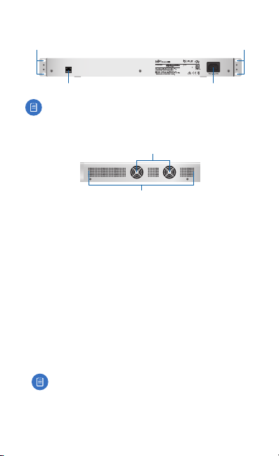
Back Panel
Mounting Holes
CONSOLE
Console
Note: The Console port is reserved for future use.
Mounting Holes
Power
Side Panels
Fans
Ventilation Holes
Installation Requirements
• Phillips screwdriver
• Standard-sized, 19" wide rack with a minimum of 1U height
available
• For indoor applications, use Category 5 (or above) UTP
cabling approved for indoor use.
• For outdoor applications, shielded Category 5 (or above)
cabling should be used for all wired Ethernet connections
and should be grounded through the AC ground of the
power supply.
We recommend that you protect your networks from
harmful outdoor environments and destructive ESD events
with industrial-grade, shielded Ethernet cable from Ubiquiti
Networks. For more details, visit: www.ubnt.com/toughcable
Note: Although the cabling can be located outdoors,
the UniFi Switch itself should be housed inside a
protective enclosure.
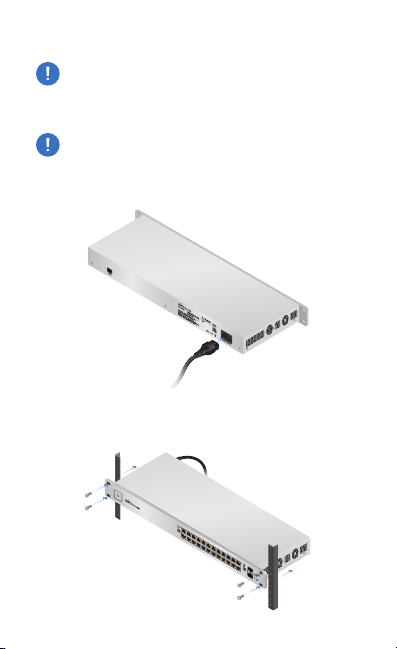
Hardware Installation
1 3 5 7 9 11 13 15 17 19 21 22
2 4 6 8 10 12 14 16 18 20 22 24
SFP1
SFP2
WARNING: FAILURE TO PROVIDE PROPER VENTILATION
MAY CAUSE FIRE HAZARD. KEEP AT LEAST 20 MM OF
CLEARANCE NEXT TO THE VENTILATION HOLES FOR
ADEQUATE AIRFLOW.
WARNING: To reduce the risk of fire or electric shock, do
not expose the UniFi Switch to rain or moisture.
1. Connect the Power Cord to the Power port of the
UniFiSwitch.
2. Attach the UniFi Switch to the rack using the four Mounting
Screws. (If the rack has square slots, then use the Cage Nuts
with the Mounting Screws.)
 Loading...