


Dual-Band airMAX® AC Radio with Dedicated Wi-Fi Management
Model: BulletAC-IP67

Introduction
Thank you for purchasing the Ubiquiti Networks® airMAX® Bullet™ AC IP67. This Quick Start Guide is designed to guide you through installation and includes the warranty terms.
Package Contents
|
|
|
|
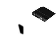
Bullet AC IP67 |
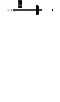
N-Type Right |
||
|
|
|
Angle Adapter |
TERMS OF USE: Ubiquiti radio devices must be professionally installed. Shielded Ethernet cable and earth grounding must be used as conditions of product warranty. TOUGHCable is designed for outdoor installations. It is the professional installer’s responsibility to follow local country regulations, including operation within legal frequency channels, output power, and Dynamic Frequency Selection (DFS) requirements.
Installation Requirements
•Shielded Category 5 (or above) cabling with drain wire should be used for all outdoor wired Ethernet connections and should be grounded through the AC ground of the PoE.
We recommend that you protect your networks from harmful outdoor environments and destructive ESD events with industrial grade, shielded Ethernet cable from Ubiquiti Networks. For more details, visit www.ubnt.com/toughcable
•Surge protection should be used for all outdoor installations. We recommend that you use two Ethernet Surge Protectors, model ETH-SP, one near the Bullet and the other at the entry point to the building. The ETH-SP will absorb power surges and safely discharge them into the ground.
ES-8-150W
To Antenna
BulletAC-IP67
ETH-SP
ETH-SP
To LAN

Hardware Overview
N-Type
Connector
Bullet AC
Radio
Ethernet Port
Rubber Washer
Cable Gland Body
Compression Seal
Compression Nut

Hardware Installation
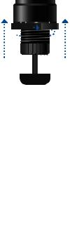
1.Unscrew the Cable Gland Body and detach it from the
Bullet AC Radio.
2.Unscrew the Compression Nut and remove the Compression Seal from the Cable Gland Body.
3.Slide the Compression Nut over the Ethernet cable with the threaded end facing the RJ-45 connector. Slip the
Compression Seal around the cable.
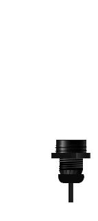
4.Feed the Ethernet cable through the Cable Gland Body and seat the Compression Seal into the Cable Gland Body.
5.Connect the Ethernet cable to the port located on the bottom of the Bullet AC Radio.
6.Securely screw the Cable Gland Body into the Bullet AC Radio so that the Rubber Washer seals the bottom of the radio.
7.Tightly screw on the Compression Nut. Ensure the Compression Seal is securely compressed and tightly sealed around the cable.
8. Connect the Bullet to the N-Type connector of the antenna.
Note: The Bullet should be mounted vertically to reduce stress on the N-Type Connector. The N-Type Right Angle Adapter may be used as needed.
 Loading...