


Quad-Radio 802.11ac Wave 2 Access Point with Dedicated Security and Beamforming Antenna
Model: UWB XG
Introduction
Thank you for purchasing the Ubiquiti Networks®
UniFi® Quad Radio 802.11ac Wave 2 Access Point with Dedicated Security and Beamforming Antenna. This Quick
Start Guide is designed to guide you through installation and includes warranty terms.
IMPORTANT: The UWB XG requires the UniFi Controller v5.7 or higher, available at: www.ubnt.com/download/unifi
Package Contents
|
|
UniFi Wi-Fi BaseStation |
Adjustment Bracket |
Pole Clamp |
Carriage Bolts |
Flange Nuts |
|
(Qty. 4) |
(Qty. 4) |
Lag Screws |
Gigabit PoE |
Power Cord |
Quick Start |
(Qty. 4) |
(50V, 1.2A) |
|
Guide |
TERMS OF USE: Ubiquiti radio devices must be professionally installed. Shielded Ethernet cable and earth grounding must be used as conditions of product warranty. TOUGHCable™ is designed for outdoor installations. It is the professional installer’s responsibility to follow local country regulations, including operation within legal frequency channels, output power, and Dynamic Frequency Selection (DFS) requirements.
Installation Requirements
•13 mm wrench
•Category 5 (or above) UTP cable for indoor installations
Outdoor Installation Requirements
•Shielded Category 5 (or above) cabling should be used for all outdoor wired Ethernet connections and should be grounded through the AC ground of the PoE.
We recommend that you protect your networks from harmful outdoor environments and destructive ESD events with industrial grade, shielded Ethernet cable from Ubiquiti Networks. For more details, visit: www.ubnt.com/toughcable
System Requirements
•Linux, Mac OS X, or Microsoft Windows 7/8/10
•Java Runtime Environment 1.8 or above recommended
•Web Browser: Google Chrome (Other browsers may have limited functionality.)
•UniFi Controller software v5.7 or newer (available at: www.ubnt.com/download/unifi)

Network Topology Requirements
•A DHCP-enabled network (for the AP to obtain an IP address as well as for the wireless clients after deployment)
•A UniFi Cloud Key or management station running the UniFi Controller v5.7 (or newer) software, located either on-site and connected to the same Layer 2 network, or off-site in the cloud or NOC
UniFi Hybrid
Cloud Install
|
|
|
|
|
|
|
|
|
|
UWB-XG |
UWB-XG |
|||
|
|
|
|
|
|
|
|
|
|
|||||
|
|
|
|
|
|
|
|
|
|
|
|
|
|
|
|
|
|
|
|
|
|
|
|
|
|
|
|
|
|
|
|
|
|
|
|
|
|
|
|
|
|
|
|
|
|
|
|
|
|
|
|
|
|
|
|
|
|
|
|
|
|
|
|
|
|
|
|
|
|
|
|
|
|
|


 UAP-XG US-16-XG
LAN
USG-PRO-4 WAN
(DHCP Server)
Internet
Remote Access to
UniFi Controller
Sample Network Diagram
All UniFi devices support off-site management controllers. For setup details, see the User Guide on the website: www.ubnt.com/download/unifi

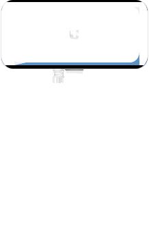
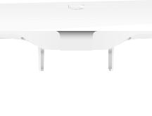
Hardware Overview
Top View
Lanyard Loop


 Mounting Bolt


 Elevation Lock Bolt
 Adjustment Bracket
Pole Clamp
LED
The RGB LED is set to the factory defaults below; however, the color and lighting pattern are software-controllable.
|
|
|
|
|
|
|
|
|
LED Color |
Status |
|
White |
Factory default, waiting to be integrated. |
|
|
Flashing White |
Initializing. |
|
|
|
|
|
|
Alternating |
Device is busy; do not touch or unplug it. |
|
|
This usually indicates that a process such |
|
||
White/Blue |
|
||
as a firmware upgrade is taking place. |
|
||
|
|
|
|
|
|
|
|
|
|
Indicates the device has been successfully |
|
Blue |
integrated into a network and is working |
|
|
|
|
properly. |
|
|
|
This is used to locate an AP. |
|
Quickly |
When you click Locate in the UniFi |
|
|
Controller software, the AP will flash. It |
|
||
Flashing Blue |
|
||
will also display the location of the AP on |
|
||
|
|
|
|
|
|
the map. |
|
Steady Blue |
Indicates the device is in an isolated state |
|
|
with Occasional |
(all WLANs are brought down until an |
|
|
Flashing |
uplink is found). |
|
|
|
|
|
|
Ports
10 GbE |
1 GbE |
|
|
|
|
|
Reset |
||||
Port |
Port |
Button |
|||
10 GbE The 10 GbE port is a 1/10 Gbps Ethernet port used to connect to the LAN and DHCP server. It can also be used to connect the power.
Note: The UWB XG can be powered using an 802.3bt PoE switch or the included Gigabit PoE adapter. For instructions, see Powering the UniFi AP.
1 GbE The 1 GbE port is a 10/100/1000 Ethernet port used for bridging. It can also be used to connect the power.
Reset The Reset button serves two functions for the UWB XG:
•Restart Press and release the Reset button quickly.
•Restore to Factory Default Settings Press and hold the
Reset button for more than five seconds.

VESA Mounting
If you choose to use your own mount, remove the four
M4 x 10 screws from the back of the UWB XG and detach the pre installed mount.
The 8-hole mounting pattern on the back of the UWB XG follows the VESA MIS-D standard and can be used with mounts that comply with this standard. Use either the 100 x 100 mm or 75 x 75 mm square hole pattern with M4 x 10 screws.
75 mm
100 mm
*640-00357-05*
640-00357-05

Hardware Installation
The UWB XG can be mounted on a pole or wall. Proceed to the appropriate instructions for your installation.
Pole Mount
1.Attach the Pole Clamp to the Adjustment Bracket.
a.Hold the Adjustment Bracket with its clamps facing you.
b.Insert the Carriage Bolts through the rectangular holes of the Adjustment Bracket.
c.Slide the single hole of the Pole Clamp over the corresponding Carriage Bolt.
d.Place one Flange Nut on each bolt.
Pole Clamp
Hole
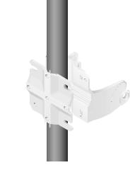
2.Mount the Adjustment Bracket on the pole and secure it.
a.Place the Adjustment Bracket against the pole.
b.Slide the three slots of the Pole Clamp over the corresponding Carriage Bolts.
c.Tighten the Flange Nuts of the bolts to 25 N · m to secure the Adjustment Bracket to the pole.
 25 N · m
Note: The mounting assembly can accommodate a
Ø 20 - 80 mm pole.
 Loading...