


 Loading...
Configuration Interface
Release Version: 1.4.1

EdgeSwitch XP User Guide |
Table of Contents |
|
Table of Contents |
Chapter 1: Overview. . . . . . . . . . . . . . . . . . . . . . . . . . . . . . . . . . . . . . . . |
. . . . . . . . 1 |
Introduction.. .. .. .. .. .. .. .. .. .. .. .. .. .. .. .. .. .. .. .. .. .. .. .. .. .. .. .. .. .. .. .. .. .. .. .. .. .. .. .. .. .. .. .. .. .. .. .. .. .. .. .. .. .. .. .. .. .. .. .. .. .. .. .. .. .. .. .. .. .. 1 |
|
Configuration Interface System Requirements.. .. .. .. .. .. .. .. .. .. .. .. .. .. .. .. .. .. .. .. .. .. .. .. .. .. .. .. .. .. .. .. .. .. .. .. .. 1 |
|
Hardware Overview.. . . . . . . . . . . . . . . . . . . . . . . . . . . . . . |
. . . . . . . . . . . . . . . . . . . . . . . . . . . . . . . . 1 |
Chapter 2: Navigation.. . . . . . . . . . . . . . . . . . . . . . . . . . . . . . . . . . . . . . . . . . . . . . 5
Accessing the Configuration Interface .. . . . . . . . . . . . . . . . . . . . . . . . . . . . . . . . . . . . . . . . . . . . 5
Configuring the EdgeSwitch 16XP .. . . . . . . . . . . . . . . . . . . . . . . . . . . . . . . . . . . . . . . . . . . . . . . . 6
Product Verification .. . . . . . . . . . . . . . . . . . . . . . . . . . . . . . . . . . . . . . . . . . . . . . . . . . . . . . . . . . . . . . 6
Interface Tabs.. . . . . . . . . . . . . . . . . . . . . . . . . . . . . . . . . . . . . . . . . . . . . . . . . . . . . . . . . . . . . . . . . . . . 6
Chapter 3: Status Tab.. . . . . . . . . . . . . . . . . . . . . . . . . . . . . . . . . . . . . . . . . . . . . . . |
7 |
Status.. . . . . . . . . . . . . . . . . . . . . . . . . . . . . . . . . . . . . . . . . . . . . . . . . . . . . . . . . . . . . . . . . . . . . . . . . . . . |
8 |
Port Status.. . . . . . . . . . . . . . . . . . . . . . . . . . . . . . . . . . . . . . . . . . . . . . . . . . . . . . . . . . . . . . . . . . . . . . |
. 8 |
Port Statistics. . . . . . . . . . . . . . . . . . . . . . . . . . . . . . . . . . . . . . . . . . . . . . . . . . . . . . . . . . . . . . . . . . . . . |
8 |
Total Throughput. . . . . . . . . . . . . . . . . . . . . . . . . . . . . . . . . . . . . . . . . . . . . . . . . . . . . . . . . . . . . . . . . |
9 |
Data Distribution.. . . . . . . . . . . . . . . . . . . . . . . . . . . . . . . . . . . . . . . . . . . . . . . . . . . . . . . . . . . . . . . . . |
9 |
Details for Port.. . . . . . . . . . . . . . . . . . . . . . . . . . . . . . . . . . . . . . . . . . . . . . . . . . . . . . . . . . . . . . . . . . |
. 9 |
Chapter 4: Device Tab . . . . . . . . . . . . . . . . . . . . . . . . . . . . . . . . . . . . . . . . . . . . . |
11 |
Firmware Update.. . . . . . . . . . . . . . . . . . . . . . . . . . . . . . . . . . . . . . . . . . . . . . . . . . . . . . . . . . . . . . . . |
12 |
Management Network Settings.. . . . . . . . . . . . . . . . . . . . . . . . . . . . . . . . . . . . . . . . . . . . . . . . . . |
12 |
Basic Settings .. . . . . . . . . . . . . . . . . . . . . . . . . . . . . . . . . . . . . . . . . . . . . . . . . . . . . . . . . . . . . . . . . . . |
13 |
Management Connection Settings. . . . . . . . . . . . . . . . . . . . . . . . . . . . . . . . . . . . . . . . . . . . . . . |
13 |
Services.. . . . . . . . . . . . . . . . . . . . . . . . . . . . . . . . . . . . . . . . . . . . . . . . . . . . . . . . . . . . . . . . . . . . . . . . . |
14 |
Spanning Tree Protocol. . . . . . . . . . . . . . . . . . . . . . . . . . . . . . . . . . . . . . . . . . . . . . . . . . . . . . . . . . |
15 |
Jumbo Frames.. .. .. .. .. .. .. .. .. .. .. .. .. .. .. .. .. .. .. .. .. .. .. .. .. .. .. .. .. .. .. .. .. .. .. .. .. .. .. .. .. .. .. .. .. .. .. .. .. .. .. .. .. .. .. .. .. .. .. .. .. .. .. .. .. .. ..16 |
|
Device Discovery.. . . . . . . . . . . . . . . . . . . . . . . . . . . . . . . . . . . . . . . . . . . . . . . . . . . . . . . . . . . . . . . . |
16 |
System Accounts.. . . . . . . . . . . . . . . . . . . . . . . . . . . . . . . . . . . . . . . . . . . . . . . . . . . . . . . . . . . . . . . . |
16 |
Device Maintenance. . . . . . . . . . . . . . . . . . . . . . . . . . . . . . . . . . . . . . . . . . . . . . . . . . . . . . . . . . . . . |
16 |
Configuration Management.. . . . . . . . . . . . . . . . . . . . . . . . . . . . . . . . . . . . . . . . . . . . . . . . . . . . . |
16 |
Chapter 5: Ports Tab .. . . . . . . . . . . . . . . . . . . . . . . . . . . . . . . . . . . . . . . . . . . . . . |
17 |
Basic Settings for Port .. . . . . . . . . . . . . . . . . . . . . . . . . . . . . . . . . . . . . . . . . . . . . . . . . . . . . . . . . . . |
18 |
Ping Watchdog for Port. . . . . . . . . . . . . . . . . . . . . . . . . . . . . . . . . . . . . . . . . . . . . . . . . . . . . . . . . . |
18 |
Spanning Tree Settings for Port.. . . . . . . . . . . . . . . . . . . . . . . . . . . . . . . . . . . . . . . . . . . . . . . . . . |
19 |
Configure Alerts for Port.. . . . . . . . . . . . . . . . . . . . . . . . . . . . . . . . . . . . . . . . . . . . . . . . . . . . . . . . . |
19 |
Chapter 6: VLANs Tab .. . . . . . . . . . . . . . . . . . . . . . . . . . . . . . . . . . . . . . . . . . . . . 21
VLANs. . . . . . . . . . . . . . . . . . . . . . . . . . . . . . . . . . . . . . . . . . . . . . . . . . . . . . . . . . . . . . . . . . . . . . . . . . . 22
Trunk .. . . . . . . . . . . . . . . . . . . . . . . . . . . . . . . . . . . . . . . . . . . . . . . . . . . . . . . . . . . . . . . . . . . . . . . . . . .22
Ubiquiti Networks, Inc. |
i |
Table of Contents |
EdgeSwitch XP User Guide |
Chapter 7: Alerts Tab . . . . . . . . . . . . . . . . . . . . . . . . . . . . . . . . . . . . . . . . . . . . . . |
23 |
Alert Log.. . . . . . . . . . . . . . . . . . . . . . . . . . . . . . . . . . . . . . . . . . . . . . . . . . . . . . . . . . . . . . . . . . . . . . . . |
23 |
System Log. . . . . . . . . . . . . . . . . . . . . . . . . . . . . . . . . . . . . . . . . . . . . . . . . . . . . . . . . . . . . . . . . . . . . . |
24 |
Chapter 8: Tools.. . . . . . . . . . . . . . . . . . . . . . . . . . . . . . . . . . . . . . . . . . . . . . . . . . . |
25 |
MAC Forwarding Table .. . . . . . . . . . . . . . . . . . . . . . . . . . . . . . . . . . . . . . . . . . . . . . . . . . . . . . . . . . |
25 |
Ping. . . . . . . . . . . . . . . . . . . . . . . . . . . . . . . . . . . . . . . . . . . . . . . . . . . . . . . . . . . . . . . . . . . . . . . . . . . . . |
25 |
Traceroute .. . . . . . . . . . . . . . . . . . . . . . . . . . . . . . . . . . . . . . . . . . . . . . . . . . . . . . . . . . . . . . . . . . . . . . |
26 |
Discovery .. . . . . . . . . . . . . . . . . . . . . . . . . . . . . . . . . . . . . . . . . . . . . . . . . . . . . . . . . . . . . . . . . . . . . . . |
26 |
Appendix A: Contact Information. . . . . . . . . . . . . . . . . . . . . . . . . . . . . . . . . . |
27 |
Ubiquiti Networks Support.. . . . . . . . . . . . . . . . . . . . . . . . . . . . . . . . . . . . . . . . . . . . . . . . . . . . . . |
27 |
ii |
Ubiquiti Networks, Inc. |

EdgeSwitch XP User Guide
Chapter 1: Overview
Introduction
Thank you for purchasing the Ubiquiti® EdgeSwitch® XP, which is part of the EdgeSwitch series:
Name |
Model |
Description |
|
|
|
EdgeSwitch 5XP |
ES-5XP |
5-port managed switch |
|
|
featuring 24V PoE |
|
|
|
EdgeSwitch 8XP |
ES-8XP |
8-port managed switch |
|
|
featuring 24V/48V PoE |
|
|
|
EdgeSwitch 16XP |
ES-16XP |
Two EdgeSwitch 8XP |
|
|
units mounted in a rack |
The EdgeSwitch is a managed switch designed to deliver
Power over Ethernet (PoE) on the 10/100/1000 ports you have configured for PoE.. It also offers a variety of features, including port monitoring, system connection and management services, Virtual Local Area Network (VLAN) configuration, Spanning Tree Protocol (STP), Ping Watchdog, and alerts setup..
This User Guide is designed to provide details about how to set up and use the Configuration Interface.. This
intuitive interface allows you to conveniently manage your EdgeSwitch using your web browser..
You can also manage your device using the Ubiquiti Network Management System, UNMS™, which lets you configure, monitor, upgrade, and back up your devices using a single software application. To get started, go to: unms.com
Configuration Interface System
Requirements
•Linux, Mac OS X, or Microsoft Windows
•Web Browser: Mozilla Firefox, Apple Safari, Google Chrome, or Microsoft Internet Explorer
Hardware Overview
Proceed to the description for your EdgeSwitch model:
•EdgeSwitch 5XP (see below)
•“EdgeSwitch 8XP” on page 2
•“EdgeSwitch 16XP” on page 3
EdgeSwitch 5XP
Back Panel
Grounding |
|
|
|
|
|
|
|
|
|
|
|
Grounding |
|||
Slot |
Ventilation |
Holes |
Power |
Slot |
|||||||||||
|
|
|
|
|
|
|
|
|
|
|
|
|
|
|
|
|
|
|
|
|
|
|
|
|
|
|
|
|
|
|
|
|
|
|
|
|
|
|
|
|
|
|
|
|
|
|
|
|
|
|
|
|
|
|
|
|
|
|
|
|
|
|
|
|
|
|
|
|
|
|
|
|
|
|
|
|
|
|
|
|
|
|
|
|
|
|
|
|
|
|
|
|
|
|
|
Ubiquiti Networks, Inc.
Chapter 1: Overview
Note: There are additional ventilation holes on the top and sides of the EdgeSwitch..
Front Panel Ports
Management |
Ports 1-5 |
||||
USB |
|
|
|
|
Reset |
|
|
|
|
||
|
|
|
|
|
|
|
|
|
|
|
|
|
|
|
|
|
|
|
|
|
|
|
|
|
|
|
|
|
|
|
|
|
|
|
|
|
|
|
|
|
|
|
|
|
|
|
|
|
|
|
|
|
|
|
|
|
|
|
|
|
|
|
|
|
|
|
|
|
|
|
|
|
|
|
|
|
|
|
|
|
|
|
|
|
|
|
|
|
|
|
|
|
|
|
|
|
|
|
|
|
|
|
|
|
|
|
|
|
|
|
|
|
|
|
|
|
|
|
|
|
|
|
|
|
|
|
|
|
|
|
|
|
|
|
|
|
|
|
|
|
|
|
|
|
|
|
|
|
|
|
|
Interface |
Description |
|||||||||||||||||
Management |
10/100 Mbps port used to access the |
|||||||||||||||||
EdgeSwitch Configuration Interface.. |
||||||||||||||||||
|
|
|
|
|||||||||||||||
|
|
|||||||||||||||||
USB |
Reserved for future use.. |
|||||||||||||||||
|
|
|||||||||||||||||
Ports 1-5 |
10/100/1000 Mbps ports for switching |
|||||||||||||||||
|
|
|
|
and PoE (also available for management |
||||||||||||||
|
|
|
|
by default).. |
||||||||||||||
|
|
|
|
|
||||||||||||||
|
|
|
|
To reset to factory defaults, press |
||||||||||||||
Reset |
and hold the Reset button for more |
|||||||||||||||||
than 10 seconds while the unit is |
||||||||||||||||||
|
|
|
|
|||||||||||||||
|
|
|
|
powered on. |
||||||||||||||
Front Panel LEDs
Power/Link |
Speed/Link/Act |
PoE
|
|
|
|
|
|
|
|
|
|
|
|
|
|
|
|
|
|
|
|
|
|
|
|
|
|
|
|
|
|
|
|
|
|
|
|
|
|
|
|
|
|
|
|
|
|
|
|
|
|
|
|
|
|
|
|
|
|
|
|
|
|
|
|
|
|
|
|
|
|
|
|
|
|
|
|
|
|
|
|
|
|
|
|
|
|
|
|
|
|
|
|
|
|
|
|
|
|
|
|
|
|
|
|
|
|
|
|
|
|
|
|
|
|
|
|
|
|
|
|
|
|
|
|
|
|
|
|
|
|
|
|
|
|
|
|
|
|
|
|
|
|
|
|
|
|
|
|
|
|
|
|
|
|
|
|
|
|
|
|
|
|
|
|
|
|
|
|
|
|
|
|
|
|
|
|
|
|
|
|
|
|
|
|
|
|
|
|
|
|
|
|
|
|
|
|
|
|
|
|
|
|
|
|
|
|
|
|
|
|
|
|
|
|
|
|
|
|
|
|
|
|
|
|
|
|
|
|
|
|
|
|
|
|
|
|
|
|
|
|
|
|
|
|
|
|
|
|
|
|
|
|
|
|
|
|
|
|
|
|
|
LED |
|
|
State |
Status |
||||||||||||||||||||
|
|
|
|
|
|
|
|
|
|||||||||||||||||
|
|
|
|
|
|
|
Off |
No Power/No Link |
|||||||||||||||||
|
|
|
|
|
|
|
|
|
|
|
|||||||||||||||
|
|
|
|
|
|
|
|
|
|
After bootup, the LED indicates |
|||||||||||||||
Management |
|
|
|
|
|
|
|
|
|
power.. After an initial link is |
|||||||||||||||
Power/ |
|
|
|
|
|
established, the LED indicates a |
|||||||||||||||||||
|
|
|
|
|
|
||||||||||||||||||||
|
|
|
|
|
|
10/100 Mbps connection.. If the |
|||||||||||||||||||
|
Link |
|
|
Amber |
link terminates, the LED turns |
||||||||||||||||||||
|
|
|
|
|
|
|
|
|
|
off until a link is re-established.. |
|||||||||||||||
|
|
|
|
|
|
|
|
|
|
If the unit reboots, the LED will |
|||||||||||||||
|
|
|
|
|
|
|
|
|
|
again indicate power until a |
|||||||||||||||
|
|
|
|
|
|
|
|
|
|
link is established.. |
|||||||||||||||
|
PoE |
|
|
Off |
No Power over Ethernet |
||||||||||||||||||||
|
|
|
|
|
|
|
|
|
|
|
|
|
|
|
|
|
|
|
|
|
|
||||
|
|
|
Green |
24V Power over Ethernet |
|||||||||||||||||||||
|
|
|
|
|
|
|
|||||||||||||||||||
|
|
|
|
|
|
|
|
|
|||||||||||||||||
|
|
|
|
|
|
|
Off |
No link |
|||||||||||||||||
|
|
|
|
|
|
|
|
|
|||||||||||||||||
5 |
|
|
|
|
|
|
Amber |
Link established at |
|||||||||||||||||
1- |
|
|
|
|
|
|
|
|
|
10/100 Mbps |
|||||||||||||||
Ports |
Speed/ |
|
|
|
|
|
|||||||||||||||||||
|
|
|
|
|
|
|
|
|
|
|
|
|
|
|
|
|
|
|
|
|
|||||
|
|
|
Amber |
Link activity at 10/100 Mbps |
|||||||||||||||||||||
|
Link/ |
|
|
Flashing |
|||||||||||||||||||||
|
Act |
|
|
|
|
|
|
|
|
|
|
|
|
|
|
|
|
|
|
||||||
|
|
|
Green |
Link established at 1000 Mbps |
|||||||||||||||||||||
|
|
|
|
|
|
|
|||||||||||||||||||
|
|
|
|
|
|
|
|
|
|
|
|
|
|
|
|
|
|
|
|
|
|
|
|
||
|
|
|
|
|
|
|
Green |
Link activity at 1000 Mbps |
|||||||||||||||||
|
|
|
|
|
|
|
Flashing |
||||||||||||||||||
|
|
|
|
|
|
|
|
|
|
|
|
|
|
|
|
|
|
|
|
|
|
|
|||
|
|
|
|
|
|
|
|
|
|
|
|
|
|
|
|
|
|
|
|
|
|
|
|
|
|
1
Chapter 1: Overview
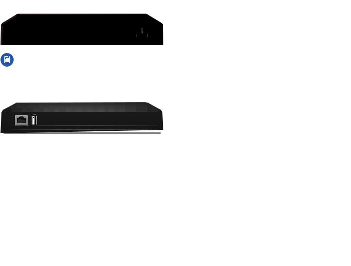
EdgeSwitch 8XP
Back Panel
|
|
Ventilation |
Holes |
Power |
|||||
|
|
|
|
|
|
|
|
|
|
|
|
|
|
|
|
|
|
|
|
|
|
|
|
|
|
|
|
|
|
|
|
|
|
|
|
|
|
|
|
|
|
|
|
|
|
|
|
|
|
|
|
|
|
|
|
|
|
|
|
|
|
|
|
|
|
|
|
|
|
Note: There are additional ventilation holes on the top and sides of the EdgeSwitch..
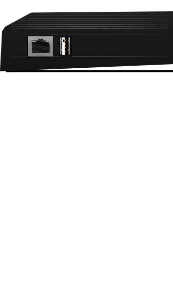
Front Panel Ports
Management |
Ports 1-8 |
USB |
Reset |
Interface |
Description |
|
Management |
10/100 Mbps port used to access the |
|
EdgeSwitch Configuration Interface.. |
||
|
||
USB |
Reserved for future use.. |
|
|
|
|
Ports 1-8 |
10/100/1000 Mbps ports for switching |
|
|
and PoE (also available for management |
|
|
by default).. |
To reset to factory defaults, press
Reset and hold the Reset button for more than 10 seconds while the unit is
powered on.
|
|
|
|
|
|
|
|
|
|
|
|
|
|
|
|
|
EdgeSwitch XP User Guide |
|||||||||||||||||||||||
Front Panel LEDs |
|
|
|
|
|
|
|
|
|
|
|
|
|
|
|
|
|
|
|
|
|
|
|
|
|
|
||||||||||||||
|
|
|
|
Power/Link |
|
|
|
|
Speed/Link/Act |
|||||||||||||||||||||||||||||||
|
|
|
|
|
|
|
|
|
|
|
|
|
|
|
|
|
|
PoE |
|
|
|
|||||||||||||||||||
|
|
|
|
|
|
|
|
|
|
|
|
|
|
|
|
|
|
|
|
|
|
|
|
|
|
|
|
|
|
|
|
|
|
|
|
|
|
|
|
|
|
|
|
|
|
|
|
|
|
|
|
|
|
|
|
|
|
|
|
|
|
|
|
|
|
|
|
|
|
|
|
|
|
|
|
|
|
|
|
|
|
|
|
|
|
|
|
|
|
|
|
|
|
|
|
|
|
|
|
|
|
|
|
|
|
|
|
|
|
|
|
|
|
|
|
|
|
|
|
|
|
|
|
|
|
|
|
|
|
|
|
|
|
|
|
|
|
|
|
|
|
|
|
|
|
|
|
|
|
|
|
|
|
|
|
|
|
|
|
|
|
|
|
|
|
|
|
|
|
|
|
|
|
|
|
|
|
|
|
|
|
|
|
|
|
|
|
|
|
|
|
|
|
|
|
|
|
|
|
|
|
|
|
|
|
LED |
State |
Status |
|
|
Off |
No Power/No Link |
|
|
|
|
|
|
|
After bootup, the LED indicates |
Management |
|
|
power.. After an initial link is |
Power/ |
|
established, the LED indicates a |
|
|
|
||
|
|
10/100 Mbps connection.. If the |
|
|
Link |
Amber |
link terminates, the LED turns |
|
|
|
off until a link is re-established.. |
|
|
|
If the unit reboots, the LED will |
|
|
|
again indicate power until a |
|
|
|
link is established.. |
|
|
Off |
No Power over Ethernet |
|
|
|
|
|
PoE |
Green |
24V Power over Ethernet |
|
|
|
|
|
|
Amber |
48V Power over Ethernet |
1-8 |
|
Off |
No link |
|
|
|
|
|
Amber |
Link established at |
|
Ports |
Speed/ |
|
10/100 Mbps |
|
|
||
|
Amber |
|
|
|
Link/ |
Link activity at 10/100 Mbps |
|
|
Flashing |
||
|
Act |
|
|
|
Green |
Link established at 1000 Mbps |
|
|
|
||
|
|
|
|
|
|
Green |
Link activity at 1000 Mbps |
|
|
Flashing |
|
|
|
|
2 |
Ubiquiti Networks, Inc. |
EdgeSwitch XP User Guide |
Chapter 1: Overview |
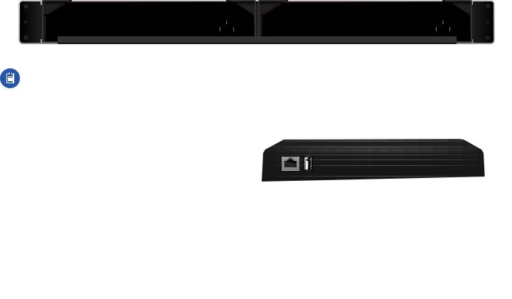
EdgeSwitch 16XP
A and B designate the two EdgeSwitch 8XP devices housed in the rack.. This may be useful for the Location setting on the Device tab in the Configuration Interface (for more information, go to “Basic Settings” on page 13)..
Back Panel
Mounting |
|
Ventilation |
Holes |
|
|
|
|
Ventilation Holes |
Mounting |
|||||||||||||||||||
Screws |
|
|
|
|
|
|
Power |
|
|
|
|
|
|
|
Power |
|
Screws |
|||||||||||
|
|
|
|
|
|
|
|
|
|
|
|
|
|
|
|
|
|
|
|
|
|
|
|
|
|
|
|
|
|
|
|
|
|
|
|
|
|
|
|
|
|
|
|
|
|
|
|
|
|
|
|
|
|
|
|
|
|
|
|
|
|
|
|
|
|
|
|
|
|
|
|
|
|
|
|
|
|
|
|
|
|
|
|
|
|
|
|
|
|
|
|
|
|
|
|
|
|
|
|
|
|
|
|
|
|
|
|
|
|
|
|
|
|
|
|
|
|
|
|
|
|
|
|
|
|
|
|
|
|
|
|
|
|
|
|
|
|
|
|
|
|
|
|
|
|
|
|
|
|
|
|
|
|
|
|
|
|
|
|
|
|
|
|
|
|
|
|
|
|
|
|
|
|
|
|
|
|
|
|
|
|
|
|
|
|
|
|
|
|
|
|
|
|
|
|
|
|
|
|
|
|
|
|
|
|
|
|
|
|
|
|
|
|
|
|
|
|
|
|
|
|
|
|
|
|
|
|
|
|
|
|
|
|
|
|
|
|
|
|
|
|
|
|
|
|
|
|
|
|
|
|
|
|
|
|
|
|
|
|
|
EdgeSwitch B |
EdgeSwitch A |
Note: There are additional ventilation holes on the top and sides of the EdgeSwitch..
Front Panel Ports
Management |
Ports 1-8 |
|
|
|
|
|
Management |
Ports 1-8 |
|||||||||||||||
|
|
USB |
|
|
|
|
Reset |
|
|
|
|
USB |
|
|
|
Reset |
|||||||
|
|
|
|
|
|
|
|
|
|
|
|
|
|
|
|
|
|
|
|
|
|
|
|
|
|
|
|
|
|
|
|
|
|
|
|
|
|
|
|
|
|
|
|
|
|
|
|
|
|
|
|
|
|
|
|
|
|
|
|
|
|
|
|
|
|
|
|
|
|
|
|
|
|
|
|
|
|
|
|
|
|
|
|
|
|
|
|
|
|
|
|
|
|
|
|
|
EdgeSwitch A |
EdgeSwitch B |
|
|
|
Interface |
Description |
|
|
|
|
Management |
10/100 Mbps port used to access the EdgeSwitch Configuration Interface.. |
|
Ports 1-8 |
10/100/1000 Mbps ports for switching and PoE (also available for management by default).. |
|
|
|
|
USB |
Reserved for future use.. |
|
|
|
|
Reset |
To reset to factory defaults, press and hold the Reset button for more than 10 seconds while the unit is |
|
powered on.. |
|
|
|
|
|
|
|
|
Ubiquiti Networks, Inc. |
3 |
Chapter 1: Overview
Front Panel LEDs
Power/Link
|
LED |
State |
Management |
|
Off |
Power/ |
|
|
|
|
|
|
Link |
Amber |
|
|
Off |
|
PoE |
Green |
|
|
Amber |
1-8 |
|
Off |
|
Amber |
|
Ports |
Speed/ |
Amber |
|
||
|
Link/ |
|
|
Flashing |
|
|
Act |
|
|
Green |
|
|
|
|
|
|
Green |
|
|
Flashing |
|
|
|
EdgeSwitch XP User Guide
Speed/Link/Act
PoE
Status
No Power/No Link
After bootup, the LED indicates power.. After an initial link is established, the LED indicates a 10/100 Mbps connection.. If the link terminates, the LED turns off until a link is re-established.. If the unit reboots, the LED will again indicate power until a link is established..
No Power over Ethernet
24V Power over Ethernet
48V Power over Ethernet
No link
Link established at
10/100 Mbps
Link activity at 10/100 Mbps
Link established at 1000 Mbps
Link activity at 1000 Mbps
4 |
Ubiquiti Networks, Inc. |
EdgeSwitch XP User Guide
Chapter 2: Navigation
The Configuration Interface is an advanced operating system accessed through a simple and intuitive user interface.. The EdgeSwitch uses the Configuration Interface for convenient configuration and management via a web browser..
If your EdgeSwitch model is the EdgeSwitch 5XP or EdgeSwitch 8XP, proceed to the next section, Accessing the Configuration Interface..
If your EdgeSwitch model is the EdgeSwitch 16XP, proceed to “Configuring the EdgeSwitch 16XP” on page 6..
Accessing the Configuration Interface
Connect to the Configuration Interface by performing the following steps:
1.Ensure that your computer (or other host machine) is connected to the Management port on the EdgeSwitch..
Note: By default, you can configure the EdgeSwitch via any port; however, we recommend the Management port.. (Access to the Configuration Interface can be limited to the Management port only.. You can configure this setting on the Device tab; see “Management Network Settings” on page 12..)
Chapter 2: Navigation
2.Configure the Ethernet adapter on your host system with a static IP address on the 192..168..1..x subnet (for example, 192..168..1..100)..
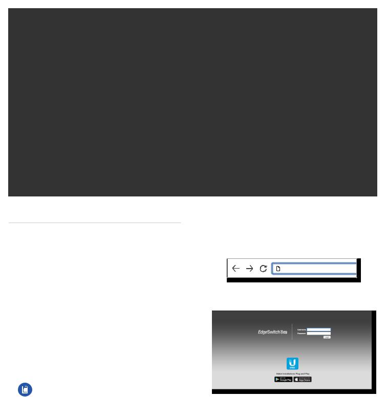
3.Launch your web browser.. Type https://192.168.1.20 in the address field.. Press enter (PC) or return (Mac)..
https://192.168.1.20
4.The login screen will appear.. Enter ubnt in the Username and Password fields.. Click Login..
5.The Configuration Interface will appear, allowing you to customize your settings as needed.. You can enable PoE on the Ports tab; see “Basic Settings for Port” on page 18..
Ubiquiti Networks, Inc. |
5 |
Chapter 2: Navigation
Configuring the EdgeSwitch 16XP
EdgeSwitch A and B have the same default IP address, 192.168.1.20, so you will need to change the IP address of at least one EdgeSwitch.. Follow the instructions in this section to configure one EdgeSwitch at a time, starting with EdgeSwitch A.
1.Ensure that your computer (or other host machine) is connected to the Management port on the EdgeSwitch..
Note: By default, you can configure the EdgeSwitch via any port; however, we recommend the Management port.. (Access to the Configuration Interface can be limited to the Management port only.. You can configure this setting on the Device tab; see “Management Network Settings” on page 12..)
2.Configure the Ethernet adapter on your host system with a static IP address on the 192..168..1..x subnet (e..g.., 192..168..1..100)..
3.Launch your web browser.. Type https://192.168.1.20 in the address field.. Press enter (PC) or return (Mac)..
https://192.168.1.20
4.The login screen will appear.. Enter ubnt in the Username and Password fields.. Click Login..
5.Change the Static Management IP Address to a unique IP address on the Device tab.. Click Save Changes..
EdgeSwitch XP User Guide
6.You can enable PoE on the Ports tab and customize additional settings as needed..
7.Disconnect the Ethernet cable from the Management port of EdgeSwitch A and connect it to the Management port of EdgeSwitch B.. Then repeat steps 1-5 on EdgeSwitch B..
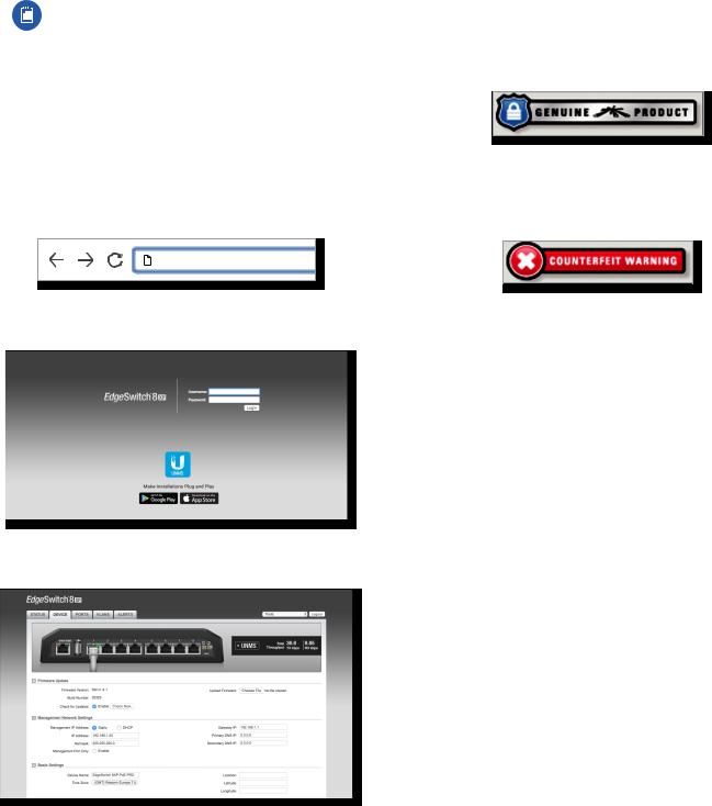
Product Verification
The Configuration Interface will verify whether a product is genuine or counterfeit..
For a genuine EdgeSwitch, the Configuration Interface will display a Genuine Product logo in the lower left corner of the screen..
For any product that is not an official Ubiquiti product, the Configuration Interface will display a counterfeit warning.. Please contact Ubiquiti at support@ubnt.com regarding this product..
Interface Tabs
The Configuration Interface contains five main tabs, each of which provides a web-based management page to configure a specific aspect of the EdgeSwitch.. This User Guide covers each tab with a chapter.. For details on a specific tab, refer to the appropriate chapter..
•Status The “Status Tab” on page 7 displays status information and statistics for each port..
•Device The “Device Tab” on page 11 configures system settings and services for the EdgeSwitch..
•Ports The “Ports Tab” on page 17 configures settings and services for each port..
•VLANs The “VLANs Tab” on page 21 configures Virtual Local Area Networks (VLANs) for the various ports..
•Alerts The “Alerts Tab” on page 23 displays alerts if alert logging is configured and system log messages if system logging is enabled..
Each page also contains a Tools drop-down menu to access network administration and monitoring tools:
•“MAC Forwarding Table” on page 25
•“Ping” on page 25
•“Traceroute” on page 26
•“Discovery” on page 26
6 |
Ubiquiti Networks, Inc. |
Loading...