


In-Wall 802.11ac
Wi-Fi Access Point
Model: UAP-AC-IW

Introduction
Thank you for purchasing the Ubiquiti Networks® UniFi® AC In Wall Wi-Fi Access Point. This Quick Start Guide is designed to guide you through installation and also includes warranty terms.
IMPORTANT: UniFi Controller v5.4 is recommended for managing the UAP-AC-IW and is available for download at: www.ubnt.com/download/unifi
Package Contents
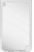
Cover Plate |
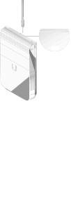
UAP-AC-IW |
Back Plate |
|
Wall-Mount Screws |
Security Torx |
Phillips Screws |
Quick Start |
(Qty. 4) |
Screws (Qty. 2) |
(Qty. 2) |
Guide |
Installation Requirements
•Pre-installed electrical wall box
•Category 5 (or above) UTP cabling approved for indoor use
•Phillips and flathead screwdrivers
•T10 Security Torx bit (for Security Torx Screw option)
•UniFi Switch with PoE
IMPORTANT: The UAP-AC-IW requires a UniFi Switch with PoE for power. Passive PoE adapters are not recommended.
TERMS OF USE: It is the customer’s responsibility to follow local country regulations, including operation within legal frequency channels, output power, indoor cabling requirements, and Dynamic Frequency Selection (DFS) requirements.
System Requirements
•Linux, Mac OS X, or Microsoft Windows 7/8/10
•Java Runtime Environment 1.6 (1.8 or newer recommended)
•Web Browser: Google Chrome (Other browsers may have limited functionality.)
•UniFi Controller software v5.4 or newer (available at: www.ubnt.com/download/unifi)
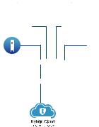
Network Topology Requirements
•A DHCP-enabled network (for the AP to obtain an IP address as well as for the wireless clients after deployment)
•A UniFi Cloud Key or management station running the UniFi Controller v5.4 (or newer) software, located either on-site and connected to the same Layer 2 network, or off-site in the cloud or NOC
UAP-AC-IW
UniFi Cloud Key
(UniFi Controller)
UAP-AC-PRO UAP-AC-LR
UAP-AC-M-PRO
US-48-500W
LAN
USG-PRO-4 |
WAN |
(DHCP Server) |
|
Internet
Remote Access to
UniFi Controller
Sample Network Diagram
All UniFi devices support off-site management controllers. For setup details, see the User Guide on the website: www.ubnt.com/download/unifi
Hardware Overview
Back Panel
PoE In + Data
PoE In + Data 10/100/1000 Ethernet port supports data and 802.3at PoE+ input. The UAP-AC-IW itself requires 7W.
802.3at PoE+ input is required to use PoE passthrough. Connect this port to a UniFi Switch with PoE that is connected to your LAN and DHCP server.
Bottom Panel
PoE Out |
|
|
|
Reset |
|
|
|
Data |
|
+ Data |
|
|
|
|
|
|
|||
|
|
|
|
|
|
|
|
|
|
|
|
|
|
|
|
|
|
|
|
|
|
|
|
|
|
|
|
|
|
|
|
|
|
|
|
|
|
|
|
|
|
|
|
|
|
|
|
|
|
|
|
|
|
|
|
|
|
|
|
PoE Out + Data 10/100/1000 Ethernet port supports data and PoE passthrough (requires 802.3at PoE+ input). The maximum PoE passthrough output is 12W.
Note: To power and connect an 802.3af device to the LAN, you must use 802.3at PoE+ input.
Reset The Reset button serves two functions for the UAP AC IW:
•Restart Press and release the Reset button quickly.
•Restore to Factory Default Settings Press and hold the
Reset button for more than five seconds.
Data 10/100/1000 Ethernet port supports data only. Used to connect a client device to the LAN.

LED
LED
Color |
State |
Status |
|
Flashing |
Initializing. |
White |
Steady |
Factory defaults, waiting for |
|
|
integration. |
White/ |
Alternating |
Device is busy; do not touch or |
Blue |
|
unplug it. This usually indicates |
|
|
that a process such as a firmware |
|
|
upgrade is taking place. |
|
Steady |
Successfully integrated into a |
|
|
network and working properly. |
|
Flashing |
This is used to locate a device. |
Blue |
|
When you click Locate in the UniFi |
|
|
Controller software, the LED will |
|
|
flash blue. The software will also |
|
|
display the location of the AP on |
|
|
the map. |
|
*640-00260-05* |
|
|
|
640-00260-05 |
Security Tab
The Security Tab helps to secure the Cover Plate after installation. If you need to remove it, use a flathead screwdriver to depress the Security Tab while detaching the
Cover Plate:
Security Tab
Back Plate
The Back Plate offers a variety of mounting holes for use with different wall boxes. Here are a few examples with the appropriate mounting holes outlined in blue:
USA or China
Europe
 Loading...