


HighIntegrated airMAX®
Model: PBE
Introduction
Thank you for purchasing the Ubiquiti Networks® PowerBeam™. This Quick Start Guide is designed to guide you through installation and also includes warranty terms.
If you want to add a radome to enclose the Dish Reflector,
Ubiquiti Networks offers the PowerBeam Radome, 400 mm, model PBE-RAD-400 as an optional accessory. Product details are available on our website at www.ubnt.com/airmax
Package Contents
Dish Reflector |
PBE-M5-400 |
|
Rear Housing |
|
Antenna Feed* |
|
|
20 |
|
|
|
010 |
|
|
|
10 |
|
|
|
Dish Bracket |
Pole Clamp |
U-Bolt |
Flange Nuts |
|
|
|
(M8, Qty. 2) |
Gigabit PoE (24V, 0.5A) |
Power Cord |
Quick Start Guide |
with Mounting Bracket |
|
|
*The PBE-M5-400 Antenna Feed has a thin gray ring around the center of the cap to differentiate it from the PBE-M5-300 Antenna Feed.
TERMS OF USE: Ubiquiti radio devices must be professionally installed. Shielded Ethernet cable and earth grounding must be used as conditions of product warranty. TOUGHCable™ is designed for outdoor installations. It is the customer’s responsibility to follow local country regulations, including operation within legal frequency channels, output power, and Dynamic
Frequency Selection (DFS) requirements.
Hardware Overview
Bottom View
Antenna Feed
Technology
Ethernet Port
Reset Button
Release Button
Dish
Reflector
Dish Bracket
Alignment Pins
Rear Housing
Release
Button Slot
Cable Door
Reset Button To reset to factory defaults, press and hold the
Reset button for more than 10 seconds while the PowerBeam is already powered on. Alternatively, the PowerBeam may be reset remotely via a Reset button located on the bottom of the
Gigabit PoE adapter.
Release Button After you assemble the PowerBeam, check the Release button; it should be fully engaged in the Release Button Slot of the Rear Housing. This ensures that the Antenna Feed is locked into place. If you need to remove the Antenna Feed, you must depress the Release button first.
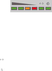
LEDs
 Signal In airOS, you can modify the wireless signal strength threshold values for each LED on the
Advanced tab under Signal LED Thresholds. The default values are shown below:
 LED will light green when the wireless signal strength is above -65 dBm.
 LED will light green when the wireless signal strength is above -73 dBm.
 LED will light amber when the wireless signal strength is above -80 dBm.
 LED will light red when the wireless signal strength is above -94 dBm.
Ethernet The Ethernet LED will light steady green when an active Ethernet connection is made and flash when there is activity.
Power The Power LED will light green when the device is connected to a power source.
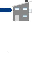
Application Examples
The PowerBeam mounted outdoors with the Dish Reflector installed provides directional outdoor coverage (gain is reflector dependent).
The PowerBeam mounted outdoors without the Dish Reflector installed provides outdoor-to-indoor coverage using the 3 dBi
Antenna Feed only.
Installation Requirements
•13 mm wrench
•Shielded Category 5 (or above) cabling should be used for all wired Ethernet connections and should be grounded through the AC ground of the PoE.
We recommend that you protect your networks from the most brutal environments and devastating ESD attacks with industrial grade shielded Ethernet cable from Ubiquiti Networks. For more details, visit www.ubnt.com/toughcable

Installation
1.Align and insert the tabs of the Dish Bracket into the slots of the Dish Reflector. Rotate the Dish Bracket counter clockwise until the tabs lock into place.
20
10 |
10 |
0 |
2.Line up the Alignment Pins of the Rear Housing with the alignment holes of the Dish Bracket. Insert the pins and push until they lock into place.
20
10 |
10 |
0 |
*640-00073-05*
640-00073-05

3.Push in the sides of the Cable Door and detach it from the
Rear Housing.
20  10
10 
0  10
10
4.Attach the Antenna Feed:
a.Insert the Antenna Feed into the Rear Housing, and push until it locks into place with a click.
b.Lightly pull the Antenna Feed to ensure that it is locked into place and the Release button is fully engaged.
Release Button
Bottom View

5.Connect the Ethernet cable:
a.Connect an Ethernet cable to the Ethernet Port of the
Antenna Feed.
b.Re-attach the Cable Door to the Rear Housing.
20  10
10 
0  10
10
6. Slide the Pole Clamp onto the Dish Bracket.
20 10  0
0  10
10 
 Loading...