


10G 16-Port Managed
Aggregation Switch
Model: US-16-XG
Introduction
Thank you for purchasing the Ubiquiti Networks® UniFi® Switch. This Quick Start Guide is designed to guide you through installation and also includes warranty terms.
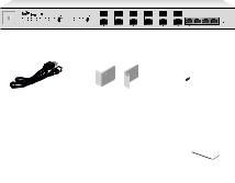
Package Contents
|
UniFi Switch |
|
Power Cord |
Rack-Mount Brackets |
Bracket Screws |
|
(Qty. 2) |
(Qty. 8) |
Mounting Screws |
Cage Nuts |
Quick Start |
(Qty. 4) |
(Qty. 4) |
Guide |
TERMS OF USE: All Ethernet cabling runs must use CAT6A (or above). It is the customer’s responsibility to follow local country regulations, including operation within legal frequency channels, output power, indoor cabling requirements, and Dynamic Frequency Selection (DFS) requirements.
System Requirements
•Linux, Mac OS X, or Microsoft Windows 7/8/10
•Java Runtime Environment 1.6 (1.8 or newer recommended)
•Web Browser: Google Chrome (Other browsers may have limited functionality.)
•UniFi Controller software v5.3.x or newer, available at: downloads.ubnt.com/unifi
Network Topology Requirements
•A DHCP-enabled network for the UniFi Switch to obtain an
IP address (connected devices will also obtain IP addresses after deployment)
•A UniFi Cloud Key or management station running the UniFi Controller v5.2.0 (or newer) software, located either on-site and connected to the same Layer 2 network, or off-site in the cloud or NOC
|
|
|
|
|
|
|
|
|
|
|
|
|
|
|
|
|
|
|
|
|
|
|
|
|
|
|
|
|
|
|
|
|
|
|
|
|
|
|
|
|
|
|
|
|
|
|
|
|
|
UAP-AC-PRO |
|||
|
|
|
|
|
|
|
|
|
|
|
|
|
|
|
|
|
|
|
|
|
|
|
||||
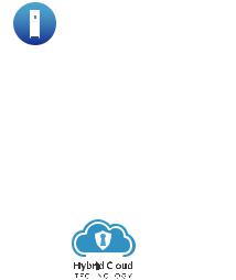
UniFi Cloud Key |
|
|
|
|
|
|
|
|
|
|
|
|
|
|
||||||||||||
(UniFi Controller) |
|
|
|
|
|
|
|
|
|
|
|
|
|
|
|
|
|
|
||||||||
|
|
|
|
|
|
|
|
|
|
|
|
|
|
|
|
|
|
|
|
|
|
|
|
|
|
|
|
|
|
|
|
|
|
|
|
|
|
|
|
|
|
|
|
|
|
|
|
|
|
|
|
|
|
|
|
|
|
|
|
|
|
|
|
|
|
|
|
|
|
|
|
|
|
|
|
|
|
|
|
|
UniFi Switch (with SFP+) |
|
|
|
|
|
|
|
UniFi Switch (with SFP+) |
|
|||||||||||||||||
|
|
|
|
|
|
|
|
|
|
|
|
|
|
|
|
|
|
|
|
|
|
|
|
|
|
|
|
|
|
|
|
|
|
|
|
|
|
|
|
|
|
|
|
|
|
|
|
|
|
|
|
|
|
|
|
|
|
|
|
|
|
|
|
|
|
|
|
|
|
|
|
|
|
|
|
|
|
|
|
|
|
|
|
|
|
|
|
|
|
|
|
|
|
|
|
|
|
|
|
|
|
|
|
|
|
|
|
|
|
|
|
|
|
|
|
|
|
|
|
|
|
|
|
|
|
|
|
|
||||||
UniFi Switch US-16-XG |
|
|
|
|
|
|
|
|
|
|
|
|
|
|
|
|
|
|||||||||
|
|
|
|
|
|
|
|
|
|
|
LAN |
|||||||||||||||
|
|
|
|
|
|
|
|
|
|
|
|
|
|
|
|
|
|
|
|
|
|
|
|
|
||
UniFi Security Gateway Pro |
|
WAN |
||||||||||||||||||||||||
(DHCP Server) |
|
|
|
|
|
|
|
|
|
|
|
|
|
|
|
|
|
|||||||||
|
|
|
|
|
|
|
|
|
|
|
Internet |
|||||||||||||||
|
|
|
|
|
|
|
|
|
|
|
|
|
|
|
|
|
|
|
|
|
|
|
|
|
|
|
|
|
|
|
|
|
|
|
|
|
|
|
|
|
|
|
|
|
|
|
|
|
|
|
|
|
|
|
|
|
|
|
|
|
|
|
|
|
|
|
|
|
|
|
|
|
|
|
|
|
|
|
|
|
|
|
|
|
|
|
|
|
|
|
|
|
|
|
|
|
|
|
|
|
|
|
|
|
|
|
|
|
|
|
|
|
|
|
|
|
|
|
|
|
|
|
|
|
|
|
|
Remote Access to |
||||||
|
|
|
|
|
|
|
|
|
|
|
|
|
|
|
|
|
|
|
|
|||||||
|
|
|
|
|
|
|
|
|
|
|
|
|
|
|
|
|
||||||||||
|
|
|
|
|
|
|
|
|
|
|
|
|
|
|
|
|
|
|
|
UniFi Controller |
||||||
All UniFi devices support off-site management controllers. For setup details, refer to the User Guide on the website: documentation.ubnt.com/unifi
Hardware Overview
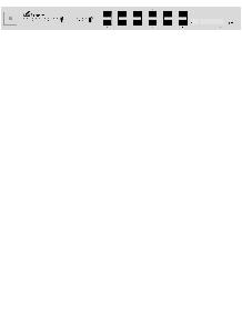
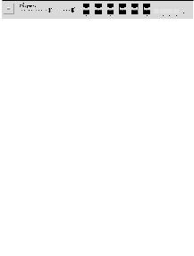
Front Panel Ports and Port LEDs
|
SFP+ 1-12 |
|
|
|
|
|
|
|
|
|
|
|
|
|
|
|
|
|
|
|
Speed/Link/Act |
|
|
|
|
|
|
SFP+ 1-12 |
RJ45 13-16 |
||||||||||||
|
|
|
|
|
|
|
|
|
|
|
|
|
|
|
|
|
|
|
|
|
|
|
|
|
|
|
|
|
|
|
|
|
|
|
|
|
|
|
|
|
|
|
|
|
|
|
|
|
|
|
|
|
|
|
|
|
|
|
|
|
|
|
|
|
|
|
|
|
|
|
|
|
|
|
|
|
|
|
|
|
|
|
|
|
|
|
|
|
|
|
|
|
|
|
|
|
|
|
|
|
|
|
|
|
|
|
|
RJ45 13-16 |
|
|
|
|
|
|
|
|
|
|
|
|
|
||||
|
|
Speed/Link/Act |
|
|
|
|
|
|
|
|
|
|
|
|
|
|||||
|
|
|
|
|
|
|
|
|
|
|
|
|
|
|
||||||
|
Port |
|
Description |
|
|
|
|
|
|
|
|
|
|
|||||||
|
|
|
|
|
|
|||||||||||||||
SFP+ 1-12 |
|
Hot-swappable SFP+ ports support 1 Gbps |
||||||||||||||||||
|
and 10 Gbps connections. |
|
|
|
|
|
|
|
|
|
|
|||||||||
|
|
|
|
|
|
|
|
|
|
|
|
|
|
|||||||
RJ45 13-16 |
|
RJ45 ports support 1 Gbps and 10 Gbps |
||||||||||||||||||
|
Ethernet connections. |
|
|
|
|
|
|
|
|
|
|
|||||||||
|
|
|
|
|
|
|
|
|
|
|
|
|
|
|||||||
|
|
|
|
|
|
|
|
|
|
|
|
|
|
|
|
|||||
|
LED |
|
State |
|
Status |
|
|
|
|
|
|
|
|
|
|
|||||
SFP+ 1-12 |
|
Off |
|
No Link |
|
|
|
|
|
|
|
|
|
|
||||||
Speed/Link/Act |
|
|
|
|
|
|
|
|
|
|
|
|
|
|
|
|
|
|
||
|
Green |
|
Solid: 1 Gbps Link Established |
|||||||||||||||||
|
|
|
|
|
||||||||||||||||
|
|
|
|
|
|
|
|
Flashing: Activity |
|
|
|
|
|
|
|
|
|
|
||
|
|
|
|
|
|
|
||||||||||||||
|
|
|
|
White |
|
Solid: 10 Gbps Link Established |
||||||||||||||
|
|
|
|
|
|
|
|
Flashing: Activity |
|
|
|
|
|
|
|
|
|
|
||
RJ45 13-16 |
|
Off |
|
No Link |
|
|
|
|
|
|
|
|
|
|
||||||
Speed/Link/Act |
|
|
|
|
|
|
|
|
|
|
|
|
|
|
|
|
|
|
||
|
Green |
|
Solid: 1 Gbps Link Established |
|||||||||||||||||
|
|
|
|
|
||||||||||||||||
|
|
|
|
|
|
|
|
Flashing: Activity |
|
|
|
|
|
|
|
|
|
|
||
|
|
|
|
|
|
|
||||||||||||||
|
|
|
|
White |
|
Solid: 10 Gbps Link Established |
||||||||||||||
|
|
|
|
|
|
|
|
Flashing: Activity |
|
|
|
|
|
|
|
|
|
|
||
|
|
|
|
|
|
|
|
|
|
|
|
|
|
|
|
|
|
|
|
|
Front Panel System LED and Button
|
|
|
|
|
|
|
|
|
|
|
|
|
|
|
|
|
|
|
|
|
|
|
|
|
|
|
|
System |
|
|
|
|
|
|
|
Reset |
|||||
System LED |
|
|
|
|
|
|
|
|
|
|
|
|
|
|
|
|
|
||||||||||
|
State |
Status |
|
|
|||||||||
White |
Factory defaults, waiting for integration. |
|
|
||||||||||
|
|
|
|
|
|
|
|
|
|
|
|
|
|
Flashing |
Initializing. |
|
|
||||||||||
White |
|
|
|||||||||||
|
|
|
|
|
|
|
|
|
|
|
|
||
Alternating |
Device is busy; do not use or unplug it. |
|
|
||||||||||
This usually indicates that a process such |
|
|
|||||||||||
White/Blue |
|
||||||||||||
as a firmware upgrade is taking place. |
|
|
|||||||||||
|
|
|
|||||||||||
|
|
|
|
||||||||||
Blue |
Successfully integrated into a network |
|
|||||||||||
and working properly. |
|
|
|||||||||||
|
|
|
|||||||||||
|
|
This is used to locate a device. |
|
|
|||||||||
|
|
When you click Locate in the UniFi |
|
|
|||||||||
Flashing Blue |
Controller software, the System LED |
|
|
||||||||||
will flash blue. The software will also |
|
|
|||||||||||
|
|
|
|
||||||||||
|
|
display the location of the UniFi Switch |
|
|
|||||||||
|
|
on the map. |
|
|
|||||||||
Reset Button |
|
|
|
|
|
|
|
|
|
|
|
|
|
|
|
|
|||||||||||
|
Button |
Description |
|||||||||||
Reset |
This button serves two functions for the |
||||||||||||
Button |
UniFi Switch: |
||||||||||||
|
|
• Restart Press and release the Reset |
|||||||||||
|
|
button quickly. |
|||||||||||
|
|
• Restore to Factory Default |
|||||||||||
|
|
Settings Press and hold the Reset button |
|||||||||||
|
|
for more than five seconds. |
|||||||||||
|
|
|
|
|
|
|
|
|
|
|
|
|
|

Back Panel Console Port
Console
|
|
|
|
|
|
|
|
|
|
|
|
|
|
|
|
|
|
|
|
|
|
|
|
|
|
|
|
|
|
|
|
|
|
|
|
Port |
Description |
||||
|
|
RJ45 serial console port for Command |
||||
|
|
Line Interface (CLI) management. Use an |
||||
|
|
RJ45 to-DB9, serial console cable, also |
||||
|
|
known as a rollover cable, to connect |
||||
|
|
the Console port to your computer. Then |
||||
|
Console |
configure the following settings as needed: |
||||
|
• |
Baud rate 115200 |
||||
|
|
|||||
|
|
• |
Data bits 8 |
|||
|
|
• Parity NONE |
||||
|
|
• |
Stop bits 1 |
|||
|
|
• Flow control NONE |
||||
*640-00251-03*
640-00251-03
Back Panel Power
|
|
|
|
|
|
|
|
|
|
|
|
|
|
|
|
|
|
|
|
|
|
|
|
|
|
|
|
|
|
|
|
|
|
|
|
|
|
|
|
|
|
|
|
|
DC Input |
Power |
||
DC Input The 25VDC input can connect a redundant or stand alone DC power source (not included) with minimum power: 56W, 25 to 16V, and 2.5 mm DC power inline connector.
Note: You can use the redundant DC power source as a hot spare; if the internal AC/DC power supply no longer provides power, the UniFi Switch will switch to the DC power source without interrupting its operation.
Power Connect the included Power Cord to the Power port.
Side Panel
Bracket Mounting |
Ventilation |
Holes |
Holes |

Hardware Installation
The UniFi Switch can be placed on a horizontal surface, mounted on a wall, or mounted in a rack.
WARNING: FAILURE TO PROVIDE PROPER VENTILATION MAY CAUSE FIRE HAZARD. KEEP AT LEAST 20 MM OF CLEARANCE NEXT TO THE VENTILATION HOLES FOR ADEQUATE AIRFLOW.
WARNING: To reduce the risk of fire or electric shock, do not expose the switch to rain or moisture.
Mounting in a Rack (Optional)
1.Attach the Rack-Mount Brackets to the UniFi Switch using the eight Bracket Screws.
2.Attach the UniFi Switch to the rack or wall using the four Mounting Screws. (If the rack has square slots, then use the
Cage Nuts with the Mounting Screws.)
 Loading...