


 Loading...
Operating System for Ubiquiti EdgeRouters
Release Version: 1.9

EdgeOS User Guide |
Table of Contents |
Table of Contents |
|
Chapter 1: Overview. . . . . . . . . . . . . . . . . . . . . . . . . . . . . . . . . . . . . . . . . . . . . . . . |
1 |
Introduction.. .. .. .. .. .. .. .. .. .. .. .. .. .. .. .. .. .. .. .. .. .. .. .. .. .. .. .. .. .. .. .. .. .. .. .. .. .. .. .. .. .. .. .. .. .. .. .. .. .. .. .. .. .. .. .. .. .. .. .. .. .. .. .. .. .. .. .. .. .. 1 |
|
Configuration Interface System Requirements.. .. .. .. .. .. .. .. .. .. .. .. .. .. .. .. .. .. .. .. .. .. .. .. .. .. .. .. .. .. .. .. .. .. .. .. .. 1 |
|
Hardware Overview and Installation.. . . . . . . . . . . . . . . . . . . . . . . . . . . . . . . . . . . . . . . . . . . . . . |
1 |
Typical Deployment Scenarios.. . . . . . . . . . . . . . . . . . . . . . . . . . . . . . . . . . . . . . . . . . . . . . . . . . . . |
1 |
Chapter 2: Using EdgeOS.. . . . . . . . . . . . . . . . . . . . . . . . . . . . . . . . . . . . . . . . . . . |
3 |
Ports and Status Information.. .. .. .. .. .. .. .. .. .. .. .. .. .. .. .. .. .. .. .. .. .. .. .. .. .. .. .. .. .. .. .. .. .. .. .. .. .. .. .. .. .. .. .. .. .. .. .. .. .. .. .. .. .. 3 |
|
Navigation.. . . . . . . . . . . . . . . . . . . . . . . . . . . . . . . . . . . . . . . . . . . . . . . . . . . . . . . . . . . . . . . . . . . . . . . |
3 |
Common Interface Options.. . . . . . . . . . . . . . . . . . . . . . . . . . . . . . . . . . . . . . . . . . . . . . . . . . . . . . . |
4 |
Chapter 3: Dashboard.. . . . . . . . . . . . . . . . . . . . . . . . . . . . . . . . . . . . . . . . . . . . . . 9
Hardware .. . . . . . . . . . . . . . . . . . . . . . . . . . . . . . . . . . . . . . . . . . . . . . . . . . . . . . . . . . . . . . . . . . . . . . . . 9
Services.. . . . . . . . . . . . . . . . . . . . . . . . . . . . . . . . . . . . . . . . . . . . . . . . . . . . . . . . . . . . . . . . . . . . . . . . . . 9
Interfaces.. . . . . . . . . . . . . . . . . . . . . . . . . . . . . . . . . . . . . . . . . . . . . . . . . . . . . . . . . . . . . . . . . . . . . . .10
Chapter 4: Traffic Analysis .. . . . . . . . . . . . . . . . . . . . . . . . . . . . . . . . . . . . . . . . . |
17 |
Traffic Analysis .. . . . . . . . . . . . . . . . . . . . . . . . . . . . . . . . . . . . . . . . . . . . . . . . . . . . . . . . . . . . . . . . . . |
17 |
Top Hosts.. . . . . . . . . . . . . . . . . . . . . . . . . . . . . . . . . . . . . . . . . . . . . . . . . . . . . . . . . . . . . . . . . . . . . . . |
18 |
Hosts............................................................................ |
18 |
Category.. . . . . . . . . . . . . . . . . . . . . . . . . . . . . . . . . . . . . . . . . . . . . . . . . . . . . . . . . . . . . . . . . . . . . . . . |
19 |
Chapter 5: Routing .. . . . . . . . . . . . . . . . . . . . . . . . . . . . . . . . . . . . . . . . . . . . . . . |
21 |
IPv6 Routing .. . . . . . . . . . . . . . . . . . . . . . . . . . . . . . . . . . . . . . . . . . . . . . . . . . . . . . . . . . . . . . . . . . . . |
21 |
Routes.. . . . . . . . . . . . . . . . . . . . . . . . . . . . . . . . . . . . . . . . . . . . . . . . . . . . . . . . . . . . . . . . . . . . . . . . . . |
22 |
OSPF.. . . . . . . . . . . . . . . . . . . . . . . . . . . . . . . . . . . . . . . . . . . . . . . . . . . . . . . . . . . . . . . . . . . . . . . . . . . . |
24 |
Chapter 6: Firewall/NAT. . . . . . . . . . . . . . . . . . . . . . . . . . . . . . . . . . . . . . . . . . . . |
27 |
Port Forwarding.. . . . . . . . . . . . . . . . . . . . . . . . . . . . . . . . . . . . . . . . . . . . . . . . . . . . . . . . . . . . . . . . . |
27 |
Firewall Policies .. . . . . . . . . . . . . . . . . . . . . . . . . . . . . . . . . . . . . . . . . . . . . . . . . . . . . . . . . . . . . . . . . |
28 |
NAT.. . . . . . . . . . . . . . . . . . . . . . . . . . . . . . . . . . . . . . . . . . . . . . . . . . . . . . . . . . . . . . . . . . . . . . . . . . . . . |
33 |
Firewall/NAT Groups. . . . . . . . . . . . . . . . . . . . . . . . . . . . . . . . . . . . . . . . . . . . . . . . . . . . . . . . . . . . . |
36 |
Chapter 7: Services .. . . . . . . . . . . . . . . . . . . . . . . . . . . . . . . . . . . . . . . . . . . . . . . |
39 |
DHCP Server .. . . . . . . . . . . . . . . . . . . . . . . . . . . . . . . . . . . . . . . . . . . . . . . . . . . . . . . . . . . . . . . . . . . . |
39 |
DNS. . . . . . . . . . . . . . . . . . . . . . . . . . . . . . . . . . . . . . . . . . . . . . . . . . . . . . . . . . . . . . . . . . . . . . . . . . . . . |
43 |
PPPoE.. . . . . . . . . . . . . . . . . . . . . . . . . . . . . . . . . . . . . . . . . . . . . . . . . . . . . . . . . . . . . . . . . . . . . . . . . . . |
44 |
Chapter 8: VPN.. . . . . . . . . . . . . . . . . . . . . . . . . . . . . . . . . . . . . . . . . . . . . . . . . . . . |
45 |
PPTP Remote Access............................................................. |
45 |
IPsec Site-to-Site................................................................. |
46 |
Ubiquiti Networks, Inc. |
i |
Table of Contents |
EdgeOS User Guide |
Chapter 9: QoS.. . . . . . . . . . . . . . . . . . . . . . . . . . . . . . . . . . . . . . . . . . . . . . . . . . . . |
49 |
Smart Queue.. . . . . . . . . . . . . . . . . . . . . . . . . . . . . . . . . . . . . . . . . . . . . . . . . . . . . . . . . . . . . . . . . . . . |
49 |
Basic Queue.. . . . . . . . . . . . . . . . . . . . . . . . . . . . . . . . . . . . . . . . . . . . . . . . . . . . . . . . . . . . . . . . . . . . . |
51 |
Advanced Queue.. . . . . . . . . . . . . . . . . . . . . . . . . . . . . . . . . . . . . . . . . . . . . . . . . . . . . . . . . . . . . . . . |
53 |
Chapter 10: Users . . . . . . . . . . . . . . . . . . . . . . . . . . . . . . . . . . . . . . . . . . . . . . . . . |
61 |
Local.. . . . . . . . . . . . . . . . . . . . . . . . . . . . . . . . . . . . . . . . . . . . . . . . . . . . . . . . . . . . . . . . . . . . . . . . . . . . |
61 |
Remote .. . . . . . . . . . . . . . . . . . . . . . . . . . . . . . . . . . . . . . . . . . . . . . . . . . . . . . . . . . . . . . . . . . . . . . . . . |
62 |
Chapter 11: Config Tree .. . . . . . . . . . . . . . . . . . . . . . . . . . . . . . . . . . . . . . . . . . . |
63 |
User Interface.. . . . . . . . . . . . . . . . . . . . . . . . . . . . . . . . . . . . . . . . . . . . . . . . . . . . . . . . . . . . . . . . . . . |
63 |
Discard and Preview.. . . . . . . . . . . . . . . . . . . . . . . . . . . . . . . . . . . . . . . . . . . . . . . . . . . . . . . . . . . . . |
64 |
CLI Modes. . . . . . . . . . . . . . . . . . . . . . . . . . . . . . . . . . . . . . . . . . . . . . . . . . . . . . . . . . . . . . . . . . . . . . . |
64 |
Configuration Example.. . . . . . . . . . . . . . . . . . . . . . . . . . . . . . . . . . . . . . . . . . . . . . . . . . . . . . . . . . |
64 |
Chapter 12: Wizards .. . . . . . . . . . . . . . . . . . . . . . . . . . . . . . . . . . . . . . . . . . . . . . |
67 |
Add a New Feature Wizard. . . . . . . . . . . . . . . . . . . . . . . . . . . . . . . . . . . . . . . . . . . . . . . . . . . . . . . |
67 |
Setup Wizards.. . . . . . . . . . . . . . . . . . . . . . . . . . . . . . . . . . . . . . . . . . . . . . . . . . . . . . . . . . . . . . . . . . . |
68 |
Feature Wizards.. . . . . . . . . . . . . . . . . . . . . . . . . . . . . . . . . . . . . . . . . . . . . . . . . . . . . . . . . . . . . . . . . |
83 |
Chapter 13: Toolbox. . . . . . . . . . . . . . . . . . . . . . . . . . . . . . . . . . . . . . . . . . . . . . . |
85 |
Ping. . . . . . . . . . . . . . . . . . . . . . . . . . . . . . . . . . . . . . . . . . . . . . . . . . . . . . . . . . . . . . . . . . . . . . . . . . . . . |
85 |
Bandwidth.. . . . . . . . . . . . . . . . . . . . . . . . . . . . . . . . . . . . . . . . . . . . . . . . . . . . . . . . . . . . . . . . . . . . . . |
86 |
Trace.. . . . . . . . . . . . . . . . . . . . . . . . . . . . . . . . . . . . . . . . . . . . . . . . . . . . . . . . . . . . . . . . . . . . . . . . . . . . |
86 |
Discover.. .. .. .. .. .. .. .. .. .. .. .. .. .. .. .. .. .. .. .. .. .. .. .. .. .. .. .. .. .. .. .. .. .. .. .. .. .. .. .. .. .. .. .. .. .. .. .. .. .. .. .. .. .. .. .. .. .. .. .. .. .. .. .. .. .. .. .. .. .. .. .. ..87 |
|
Packet Capture.. . . . . . . . . . . . . . . . . . . . . . . . . . . . . . . . . . . . . . . . . . . . . . . . . . . . . . . . . . . . . . . . . . |
87 |
Log Monitor. . . . . . . . . . . . . . . . . . . . . . . . . . . . . . . . . . . . . . . . . . . . . . . . . . . . . . . . . . . . . . . . . . . . . |
88 |
Appendix A: Command Line Interface.. . . . . . . . . . . . . . . . . . . . . . . . . . . . . |
89 |
Overview........................................................................ |
89 |
New Commands for ER-X Platform.. . . . . . . . . . . . . . . . . . . . . . . . . . . . . . . . . . . . . . . . . . . . . . . |
89 |
Access the CLI.. . . . . . . . . . . . . . . . . . . . . . . . . . . . . . . . . . . . . . . . . . . . . . . . . . . . . . . . . . . . . . . . . . . |
89 |
CLI Modes. . . . . . . . . . . . . . . . . . . . . . . . . . . . . . . . . . . . . . . . . . . . . . . . . . . . . . . . . . . . . . . . . . . . . . . |
91 |
Appendix B: Contact Information. . . . . . . . . . . . . . . . . . . . . . . . . . . . . . . . . . |
99 |
Ubiquiti Networks Support.. . . . . . . . . . . . . . . . . . . . . . . . . . . . . . . . . . . . . . . . . . . . . . . . . . . . . . |
99 |
ii |
Ubiquiti Networks, Inc. |
EdgeOS User Guide
Chapter 1: Overview
Introduction
EdgeOS™ is a powerful, sophisticated operating system from Ubiquiti Networks.. It allows you to manage your EdgeRouter and networks. This User Guide is designed for use with version 1.9 or above of the EdgeOS Configuration Interface and all of the EdgePoint and EdgeRouter models, which this User Guide will collectively refer to as EdgeRouter. Additional information is available on our website at:
http://community.ubnt.com/edgemax http://documentation.ubnt.com/edgemax
Configuration
The intuitive EdgeOS Configuration Interface allows you to conveniently manage your EdgeRouter using your web browser. (See “Using EdgeOS” on page 3 for more information.) If you need to configure advanced
features or prefer configuration by command line, you can use the config tree or the Command Line Interface (CLI). (See “Config Tree” on page 63 or “Command Line Interface” on page 89 for more information.)
Configuration Interface System Requirements
•Microsoft Windows 7, Windows 8, Windows 10, Linux, or Mac OS X
•Web Browser: Google Chrome, Mozilla Firefox, Safari 7 (or higher), Microsoft Edge, or Microsoft Internet Explorer 10 (or higher)
Hardware Overview and Installation
The Quick Start Guide that accompanied your EdgeRouter includes a hardware description and instructions for hardware installation.
Typical Deployment Scenarios
While there are numerous scenarios that are possible, this section highlights three typical deployments:
•Small Office/Home Office (SOHO) Deployment
•Service Provider Deployment
•Corporate Deployment
SOHO Deployment
Click the Wizards tab and follow the on-screen instructions. See “Wizards” on page 67 for more information.
Chapter 1: Overview
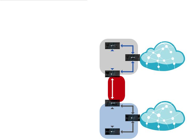
Service Provider Deployment
This scenario uses six EdgeRouter devices:
1.OSPF Area 0 to OSPF Area 1
2.OSPF Area 0 to OSPF Area 2
3.OSPF Area 1
4.OSPF Area 1 to Internet
5.OSPF Area 2
6.OSPF Area 2 to Internet
Site A |
OSPF |
|
Area 1 |
||
|
||
|
|
Internet
Site-to-Site
Link
OSPF
Area 0
Site B |
OSPF |
|
Area 2 |
||
|
||
|
|
Internet
Here are the typical steps to follow:
1.Configure the appropriate settings on the System tab (see “System” on page 4 for more information):
•Host Name
•Time Zone
•Gateway
•Name Server
•Domain Name
•NTP
2.Configure the interfaces on the Dashboard tab; see
“Interfaces” on page 10 for more information.
3.Configure OSPF settings on the Routing > OSPF tab; see “OSPF” on page 24 for more information.
4.Configure DHCP server(s) on the Services tab; see
”DHCP Server” on page 39 for more information.
5.Configure NAT rules on the Firewall/NAT > NAT tab; see ”NAT” on page 33 for more information.
Ubiquiti Networks, Inc. |
1 |
Chapter 1: Overview
6.Configure firewall rules on the Firewall/NAT > Firewall Policies tab; see ”Firewall Policies” on page 28 for more information.
7.Configure additional settings as needed for your network.
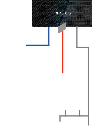
Corporate Deployment
This scenario uses a single EdgeRouter device. The three independent interfaces connect to the following:
•Internet
•DMZ
•LAN
EdgeOS User Guide
3.Configure DHCP server(s) on the Services tab; see
”DHCP Server” on page 39 for more information.
4.Configure NAT rules on the Firewall/NAT > NAT tab; see ”NAT” on page 33 for more information.
5.Configure firewall rules on the Firewall/NAT > Firewall Policies tab; see ”Firewall Policies” on page 28 for more information.
6.Configure additional settings as needed for your network.
Firewall
Policies
Internet
DMZ
LAN
Here are the typical steps to follow:
1.Configure the appropriate settings on the System tab (see “System” on page 4 for more information):
•Host Name
•Time Zone
•Gateway
•Name Server
•Domain Name
•NTP
2.Configure the interfaces on the Dashboard tab; see
“Interfaces” on page 10 for more information.
2 |
Ubiquiti Networks, Inc. |
EdgeOS User Guide
Chapter 2: Using EdgeOS
EdgeOS is a powerful, sophisticated operating system that manages your EdgeRouter. It offers both a browser based interface (EdgeOS Configuration Interface) for easy configuration and a Command Line Interface (CLI) for advanced configuration.
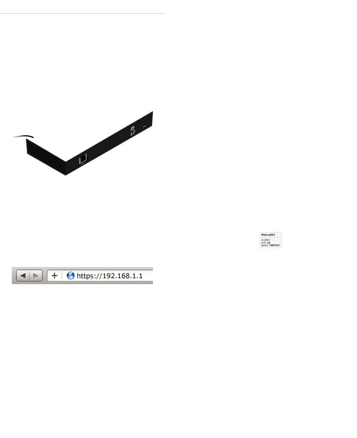
To access the EdgeOS Configuration Interface:
1.Connect an Ethernet cable from the Ethernet port of your computer to the port labeled eth0 on the EdgeRouter.
eth2
eth1
eth0
2.Configure the Ethernet adapter on your computer with a static IP address on the 192.168.1.x subnet (e.g., 192.168.1.100).
Note: As an alternative, you can connect a serial cable to the Console port of the EdgeRouter. See
“Command Line Interface” on page 89 for more information.
3.Launch your web browser. Type https://192.168.1.1 in the address field. Press enter (PC) or return (Mac).
4.The login screen will appear. Enter ubnt in the Username and Password fields. Read the Ubiquiti License Agreement, and check the box next to I agree to the terms of this License Agreement to accept it. Click
Login.
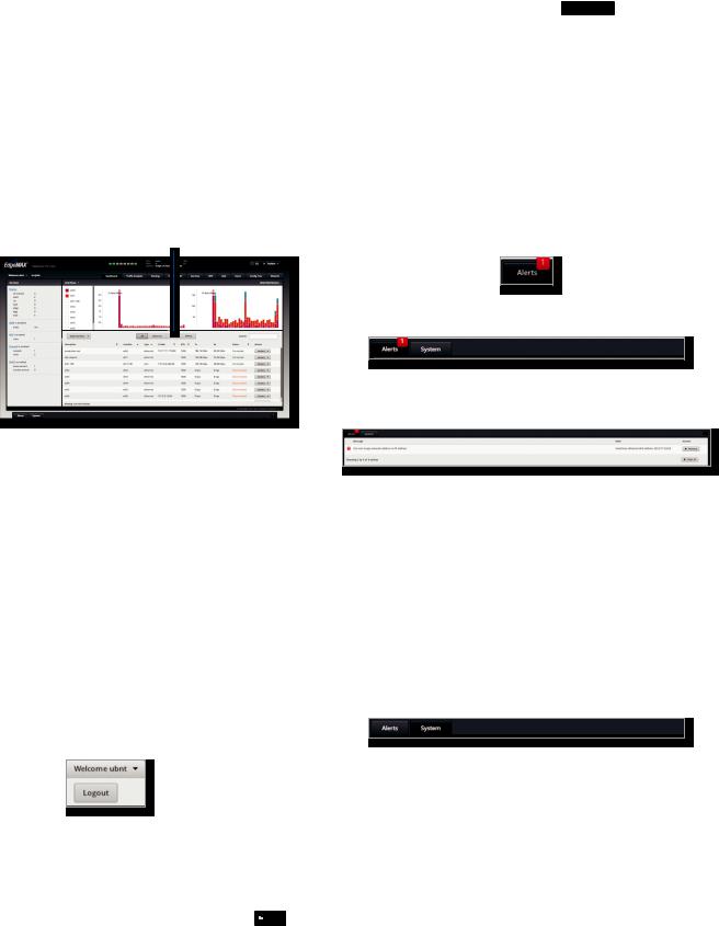
The EdgeOS Configuration Interface will appear, allowing you to customize your settings as needed.
Ubiquiti Networks, Inc.
Chapter 2: Using EdgeOS
Note: To enhance security, we recommend that you change the default login using one of the following:
•Set up a new user account on the Users > Local tab (preferred option). For details, go to “Local” on page 61.
•Change the default password of the ubnt login on the Users > Local tab. For details, go to “Configure the User” on page 62.
Ports and Status Information
The Ports image displays the active connections. A purple port indicates 10 Mbps, an amber port indicates 100 Mbps, and a green port indicates 1000 Mbps. The Status bar graphs display the following:
CPU The percentage of processing power used by the EdgeRouter.
RAM The percentage of RAM used by the EdgeRouter. Uptime The duration of the EdgeRouter’s activity.
Place your mouse over a port to view the following: Enabled/Disabled The administrative status is displayed. Link The connection status is displayed.
Speed The speed (in Mbps) and duplex mode are displayed.
Navigation
The EdgeOS software consists of 10 primary tabs, and some of these tabs have sub-tabs. This User Guide covers each tab with a chapter. For details on a specific tab, refer to the appropriate chapter.
•Dashboard “Dashboard” on page 9 displays status information about services and interfaces. You can also configure interfaces and Virtual Local Area Networks (VLANs).
•Traffic Analysis “Traffic Analysis” on page 17 displays Deep Packet Inspection (DPI) information about the applications and IP addresses using the most bandwidth.
•Routing “Routing” on page 21 configures static routes and Open Shortest Path First (OSPF) settings, including metrics, areas, and interfaces.
•Firewall/NAT “Firewall/NAT” on page 27 configures port forwarding, firewall policies, Network Address Translation (NAT) rules, and firewall/NAT groups.
•Services “Services” on page 39 configures DHCP servers, DNS forwarding, and the PPPoE server.
•VPN “VPN” on page 45 configures PPTP remote access and IPSec site-to-site VPN options.
3
Chapter 2: Using EdgeOS
•QoS “QoS” on page 49 configures Smart Queue, Basic Queue, and Advanced Queue management.
•Users “Users” on page 61 configures user accounts with administrator or operator access.
•Config Tree “Config Tree” on page 63 is a graphical representation of the CLI config settings.
•Wizards “Wizards” on page 67 offers a variety of wizards: setup wizards that configure the EdgeRouter for typical SOHO deployments, load balancing wizards, and feature wizards.
Depending on the tab you click, some of the screens display information and options in multiple sections. You can click the open/close tab to hide or display a section.
Open/Close Tab
Open/Close Tab
Common Interface Options
The common interface options are accessible from all tabs on the EdgeOS interface:
•Welcome
•CLI
•Toolbox
•Alerts
•System
Required fields are marked by a blue asterisk *. When the information  icon is displayed, you can click the icon for more information about an option.
Welcome
At the top left of the screen, click Welcome to view the Logout option:
Logout To manually log out of the EdgeRouter Configuration Interface, click this option.
CLI
Advanced users can make configuration changes using Linux commands. At the top right of the screen, click  CLI . See “Command Line Interface” on page 89 for more information.
EdgeOS User Guide
Toolbox
At the top right of the screen, click  Toolbox
  . The following network administration and monitoring tools are available:
•“Ping” on page 85
•“Bandwidth” on page 86
•“Trace” on page 86
•“Discover” on page 87
•“Packet Capture” on page 87
•“Log Monitor” on page 88
Alerts
The number of new alerts is displayed in a red popup.
At the bottom of the screen, click the Alerts tab.
A table displays the following information about each important event.
Message A description of the event is displayed.
Field The settings that are affected by the event are displayed.
Actions The following options are available:
•Remove Click this button to clear an alert.
•Clear All Click this button to clear all alerts.
Click the top right corner of the Alerts tab to close it.
System
At the bottom of the screen, click the System tab to access the device settings.
The device settings are organized into these sections:
•“Basic Settings” on page 5
•“Management Settings” on page 6
•“Configuration Management & Device Maintenance” on page 7
•“Restart & Shut Down Router” on page 7
4 |
Ubiquiti Networks, Inc. |
EdgeOS User Guide
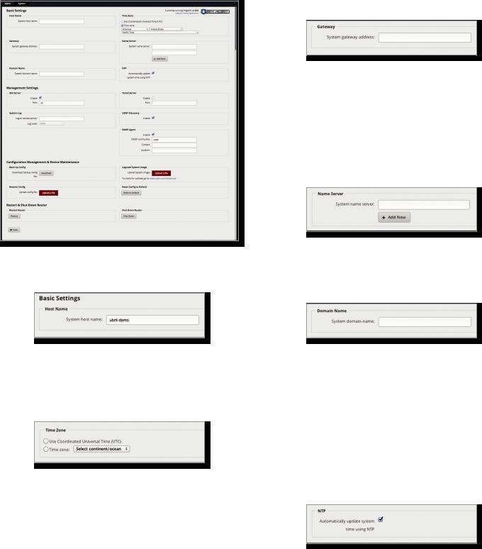
Basic Settings
Host Name
System host name Enter a name for the EdgeRouter. The host name identifies the EdgeRouter as a specific device. For example, a .com URL typically uses this format: <host_name>.domain_name.com
Time Zone
Use Coordinated Universal Time (UTC) UTC is the international time standard used by Network Time Protocol (NTP) servers. If your routers are located in multiple time zones, then you may want to use UTC.
Time zone To set your network to a specific time zone, select Time zone and configure the following:
•Select continent/ocean Select your location.
•Select country/region Select your location.
•Select time zone Select your time zone.
Chapter 2: Using EdgeOS
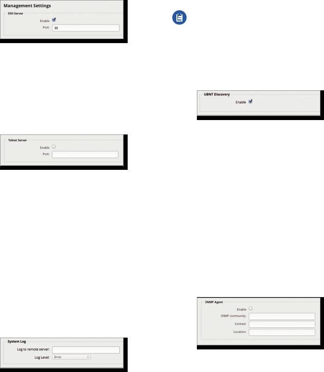
Gateway
System gateway address Enter the IP address of your gateway. This will set up your default route. If you want to set up additional default routes, configure them as static routes on the Routing tab. See “Routing” on page 21
for more information.
Name Server
Domain Name System (DNS) translates domain names to IP addresses; each DNS server on the Internet holds these mappings in its respective DNS database.
System name server Enter the IP address of your DNS server (example: 192.0.2.1 for IPv4 or 2001:db8::1 for IPv6). Click Add New to add additional servers.
Domain Name
System domain name Enter the domain name of your EdgeRouter. The domain name identifies the EdgeRouter’s network on the Internet. For example, a .com URL typically uses this format:
host_name.<domain_name>.com
NTP
NTP is a protocol for synchronizing the clocks of computer systems over packet-switched, variable-latency data networks. You can use it to set the system time on the EdgeRouter. If the System Log option is enabled, then
the system time is reported next to every log entry that registers a system event.
Automatically update system time using NTP By default, the EdgeRouter obtains the system time from a time server on the Internet.
Click Save to apply your changes.
Ubiquiti Networks, Inc. |
5 |
Chapter 2: Using EdgeOS
Management Settings
SSH Server
Enable Enabled by default. This option allows SSH (Secure Shell) access to the EdgeRouter for remote configuration by command line. SSH uses encryption and authentication, so it is a secure form of communication. See “Command Line Interface” on page 89 for more information.
Port Specify the TCP/IP port of the SSH server. The default is 22.
Telnet Server
Enable Disabled by default. This option allows Telnet access to the EdgeRouter for remote configuration by command line. Telnet is not a secure form of
communication, so we recommend SSH. See “Command Line Interface” on page 89 for more information.
Port Specify the TCP/IP port of the Telnet server. The default is 23.
System Log
Every logged message contains at least a system time and host name. Usually a specific service name that generates the system event is also specified within the message.
Messages from different services have different contexts and different levels of detail. Usually error, warning, or informational system service messages are reported; however, more detailed debug level messages can also be reported. The more detailed the system messages reported, the greater the volume of log messages generated.
EdgeOS User Guide
Log Level Select the appropriate level of log messages for reporting: Emergency, Urgent, Critical, Error, Warning, Further Investigation, Informational, or Debug. The default is Error.
Note: Properly configure the remote host to receive syslog protocol messages.
UBNT Discovery
The UBNT Discovery feature enables the EdgeRouter to be discovered by other Ubiquiti devices through the Discovery tool, which is available in the Toolbox (refer to “Discover” on page 87) or as a separate download at: www.ubnt.com/download/utilities
Enable Enabled by default. This option activates the UBNT Discovery feature.
SNMP Agent
Simple Network Monitor Protocol (SNMP) is an application layer protocol that facilitates the exchange of management information between network devices. Network administrators use SNMP to monitor network attached devices for issues that warrant attention.
The EdgeRouter contains an SNMP agent, which does the following:
•Provides an interface for device monitoring using SNMP
•Communicates with SNMP management applications for network provisioning
•Allows network administrators to monitor network performance and troubleshoot network problems
For the purpose of equipment identification, configure the SNMP agent with contact and location information:
Log to remote server This option allows the EdgeRouter to send system log messages to a remote server. Enter the remote host IP address and TCP/IP port that should receive the system log (syslog) messages. 514 is the default port for the commonly used, system message logging utilities.
Enable Disabled by default. This option activates the SNMP agent.
SNMP community Specify the SNMP community string. It is required to authenticate access to MIB (Management Information Base) objects and functions as an embedded password. The device supports a read-only community string; authorized management stations have read access to all the objects in the MIB except the community strings, but do not have write access. The device supports SNMP v1. The default is public.
6 |
Ubiquiti Networks, Inc. |
EdgeOS User Guide
Contact Specify the contact who should be notified in case of emergency.
Location Specify the physical location of the EdgeRouter. Click Save to apply your changes.
Configuration Management & Device Maintenance
The controls in this section manage the device configuration routines, firmware maintenance, and reset to factory default settings.
Back Up Config
We recommend that you back up your current system configuration before updating the firmware or uploading a new configuration.
Download backup config file Click Download to download the current system configuration file.
Note: We strongly recommend that you save the configuration file in a secure location because it includes confidential information. The user login passwords are encrypted; however, other passwords and keys (such as those used for VPN, BGP, authentication, and RADIUS) are stored in plain text.
Restore Config
Upload config file Click Upload a file to locate the configuration file previously created by the Back Up Config option. Select the file and click Choose. We recommend that you back up your current system configuration before uploading the new configuration.
Note for advanced users: You can also upload a raw configuration file, /config/config.boot, using this option.
Upgrade System Image
Download the firmware file from downloads.ubnt.com and save it on your computer.
The firmware update is compatible with all configuration settings. The system configuration is preserved while the EdgeRouter is updated with a new firmware version. However, we recommend that you back up your current system configuration before updating the firmware.
Chapter 2: Using EdgeOS
Upload system image To update the EdgeRouter with new firmware, click Upload a file and locate the new firmware file. Then click Choose.
Please be patient, as the firmware update routine can take three to seven minutes. You cannot access the EdgeRouter until the firmware update routine is completed.
WARNING: Do not power off, do not reboot, and do not disconnect the EdgeRouter from the power
supply during the firmware update process as these actions will damage the EdgeRouter!
Reset Config to Default
This option resets the EdgeRouter to the default configuration. This option will reboot the EdgeRouter, and the default configuration will be restored. We recommend that you back up your current system configuration before resetting the EdgeRouter to its default configuration.
Reset to Default To reset the EdgeRouter to its default configuration, click this option.
Restart & Shut Down Router
Restart Router
Restart To turn the EdgeRouter off and back on again, click this option.
Shut Down Router
Shut Down To turn off the EdgeRouter, click this option.
WARNING: Click Shut Down to properly shut down the EdgeRouter. An improper shutdown, such
as disconnecting the EdgeRouter from its power supply, runs the risk of data corruption!
Click the top right corner of the System tab to close it.
Ubiquiti Networks, Inc. |
7 |
Chapter 2: Using EdgeOS |
EdgeOS User Guide |
8 |
Ubiquiti Networks, Inc. |
|
EdgeOS User Guide |
Chapter 3: Dashboard |
||
|
|
|
|
|
|
|
|
|
|
|
|
|
|
|
|
|
|
|
|
Chapter 3: Dashboard
The Dashboard tab displays status information about services and interfaces. You can also configure interfaces and Virtual Local Area Networks (VLANs). Any setting marked with a blue asterisk * is required. When the information  icon is displayed, you can click the icon for more information about an option.
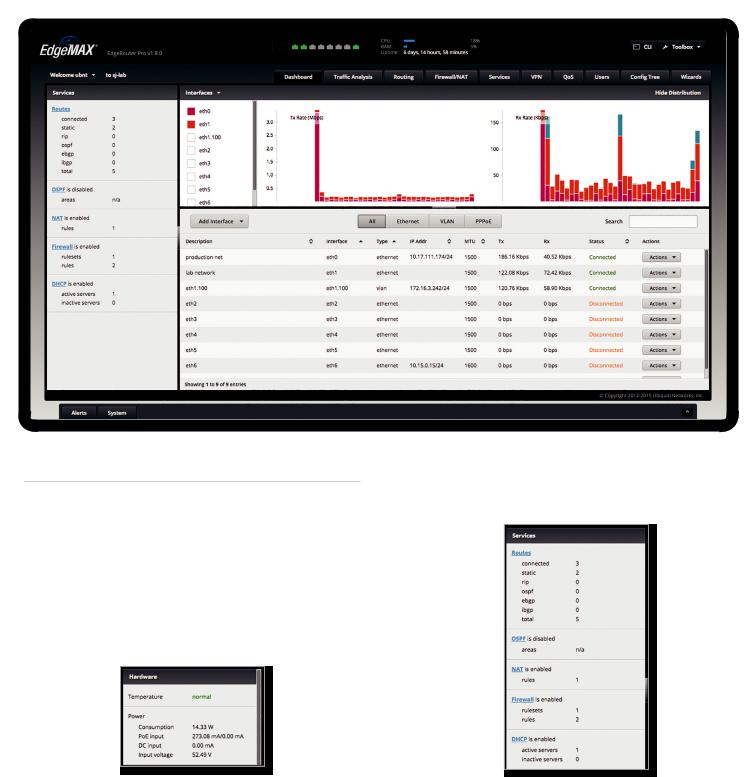
Hardware
Hardware status information is displayed for the EdgePoint EP-R8.
Temperature The status is displayed.
Power
Consumption The number of watts used by the EdgePoint is displayed.
PoE input The PoE amperage is displayed. DC input The DC amperage is displayed. Input voltage The input voltage is displayed.
Ubiquiti Networks, Inc.
Services
Services status information is displayed. Each heading is a convenient link to the appropriate tab.
Routes
The following route types are listed:
•Connected
•Static
•RIP (Routing Information Protocol)
•OSPF (Open Shortest Path First)
•EBGP (Exterior Border Gateway Protocol)
•IBGP (Interior Border Gateway Protocol)
9
Chapter 3: Dashboard
The number of each route type and the total number of routes are displayed. Click Routes to display the
Routing > Routes tab. Go to “Routes” on page 22 for more information.
OSPF
The OSPF status, settings, and number of areas are displayed. Click OSPF to display the Routing > OSPF tab. Go to “OSPF” on page 24 for more information.
NAT
The NAT (Network Address Translation) status and number of NAT rules are displayed. Click NAT to display the Firewall/NAT > NAT tab. Go to “NAT” on page 33 for more information.
Firewall
The firewall status and numbers of sets and rules are displayed. Click Firewall to display the Firewall/NAT > Firewall Policies tab. Go to “Firewall Policies” on page 28 for more information.
DHCP
The DHCP server status and numbers of active and inactive servers are displayed. Click DHCP to display the
Services tab. Go to “DHCP Server” on page 39 for more information.
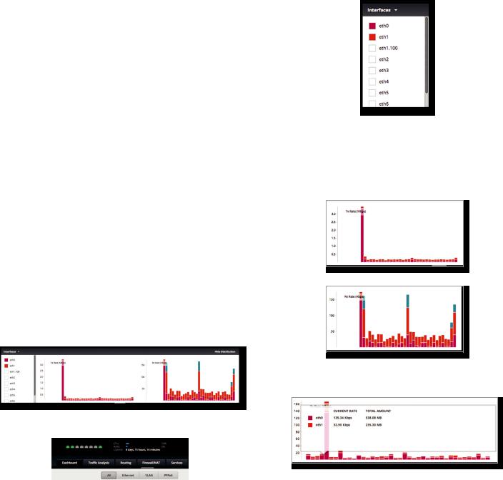
Interfaces
Distribution
Click Hide Distribution to hide the Interfaces>Distribution section. Click the remaining open/close tab to display the
Interfaces > Distribution section again.
Open/Close Tab
EdgeOS User Guide
Select the physical or virtual interfaces you want to display from the Interfaces column. Click the  to hide or display this column.
The TX Rate and RX Rate bar graphs display the current data traffic, which is color coded to match the
corresponding interface. The graph scale and throughput dimension (Mbps, for example) change dynamically depending on the mean throughput value. The statistics are updated automatically.
Place your mouse over a bar to view the Current Rate and Total Amount of traffic for the selected interfaces.
10 |
|
|
|
Ubiquiti Networks, Inc. |
|
|
|
||
|
|
|
||
|
|
|
||
|
|
|
||
|
|
|
EdgeOS User Guide
All/Ethernet/VLAN/PPPoE
Add Interface To create a new VLAN or PPPoE interface, click Add Interface. Then follow the appropriate instructions for your interface type.
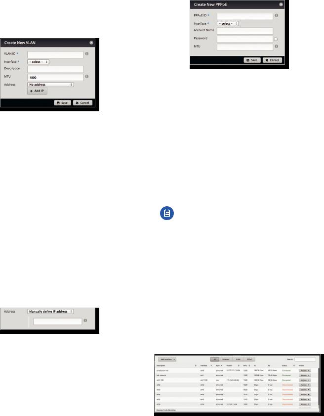
Add VLAN
The Create a New VLAN screen appears.
•VLAN ID The VLAN ID is a unique value assigned to each VLAN at a single device; every VLAN ID represents a different VLAN. The valid VLAN ID range is 0 to 4094.
•Interface Select the appropriate interface.
•Description Enter keywords to describe this VLAN.
•MTU Enter the MTU (Maximum Transmission Unit) value, which is the maximum packet size (in bytes) that a network interface can transmit. For the ER X, ER X SFP, and EP R6, the valid MTU range is 68 to 2018. For all other models, the valid MTU range is 68 to 9000. The default is 1500.
•Address Select one of the following:
-- No address The VLAN uses no address settings. (In most cases, an address is needed.)
-- Use DHCP The VLAN acquires network settings from a DHCPv4 server.
-- Use DHCP for IPv6 The VLAN acquires network settings from a DHCPv6 server.
-- Manually define IP address(es) Enter the static IP address (example: 192.0.2.1/24 for IPv4 or
2001:db8::1/32 for IPv6).
-- Add IP Click Add IP to enter additional IP addresses. Click Save to apply your changes, or click Cancel.
Ubiquiti Networks, Inc.
Chapter 3: Dashboard
Add PPPoE
The Create a New PPPoE screen appears.
•PPPoE ID The PPPoE ID is a unique value assigned to each PPPoE connection at a single device; every PPPoE ID represents a different PPPoE connection. The valid PPPoE ID range is 0 to 15.
•Interface Select the appropriate interface.
•Account Name Enter the username to connect to the PPPoE server; this must match the username configured on the PPPoE server.
•Password Enter the password to connect to the PPPoE server; this must match the password configured on the PPPoE server. Check the box to display the password.
•MTU Enter the MTU (Maximum Transmission Unit) value, which is the maximum packet size (in bytes) that a network interface can transmit. The valid MTU range is 68 to 1500. The default is 1492.
Note: Setting the MTU higher than 1492 will require ISP support and also require increasing the MTU value of the parent interface (ethX) accordingly.
Click Save to apply your changes, or click Cancel.
Search Allows you to search for specific text. Begin typing; there is no need to press enter. The results are filtered in real time as soon as you type two or more characters.
All/Ethernet/VLAN/PPPoE Click the appropriate tab to filter the interfaces as needed.
•All All interfaces are displayed by default.
•Ethernet All of the Ethernet interfaces are displayed.
•VLAN All VLANs are displayed.
A table displays the following information about each interface. Click a column heading to sort by that heading.
Description The keywords you entered to describe the interface are displayed.
11
Chapter 3: Dashboard
Interface The name of the interface is displayed.
Note: A switch interface is created by default (EdgeRouter PoE, EdgeRouter X, EdgeRouter X SFP, or EdgePoint EP-R6 only); however, there are no switched ports by default. To configure ports for the switch interface, click Actions > Config and go to the appropriate section:
•“Configure the Switch (EdgeRouter PoE)” on page 14
•“Configure the Switch (EdgeRouter X Platform)” on page 14
Type The type of interface is displayed.
PoE (Available for the EdgePoint EP-R6, EdgePoint EP-R8, or EdgeRouter PoE only.) The status (off) or voltage of the PoE feature is displayed.
IP Addr The IP address of the interface is displayed.
MTU The MTU (Maximum Transmission Unit) value of the interface is displayed. This is the maximum packet size (in bytes) that the interface can transmit.
TX The transmit speed of the interface is displayed. RX The receive speed of the interface is displayed.
Status The connection status of the interface is displayed.
Actions Click the Actions button to access the following options:
•Config To configure the interface, click Config. Proceed to the appropriate interface type:
-- ethernet If the interface is a physical port, go to the Configure the Interface section in the next column.
-- VLAN If the interface is a VLAN, go to “Configure the VLAN” on page 13.
-- PPPoE If the interface is a PPPoE connection, go to
“Configure PPPoE” on page 13.
-- switch If the interface is a switch (available for the EdgeRouter PoE only), go to “Configure the Switch (EdgeRouter PoE)” on page 14.
-- switch If the interface is a switch (available for the EdgeRouter PoE only), go to “Configure the Switch (EdgeRouter X Platform)” on page 14.
•PoE (Available for the EdgePoint EP-R6, EdgePoint EP-R8, or EdgeRouter PoE only.) To configure the PoE settings, click PoE. Go to “Configure the PoE Settings” on page 15.
•Disable Disable the interface while keeping its configuration. (The switch interface cannot be disabled.)
Note: If you disable a port, its PoE functionality remains. (This applies only to the EdgeRouter PoE.)
•Delete (Available for VLANs only.) Delete the VLAN from the EdgeRouter configuration.
EdgeOS User Guide
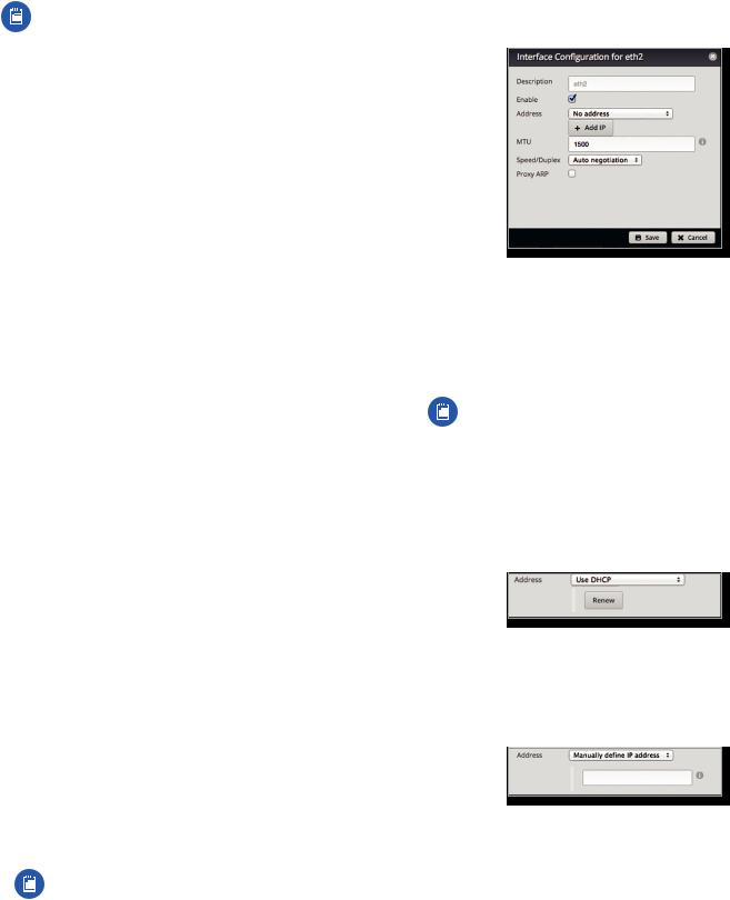
Configure the Interface
After you click Config, the Interface Configuration screen appears.
Make changes as needed.
•Description Enter keywords to describe this interface.
•Enable Check the box to enable the interface. All of the interfaces are saved in the system configuration file; however, only the enabled interfaces are active on the device.
Note: If you disable a port, its PoE functionality remains. (This applies only to the EdgeRouter PoE.)
•Address Select one of the following:
-- No address The interface uses no address settings. (In most cases, an address is needed.)
-- Use DHCP The interface acquires network settings from a DHCPv4 server. Click the Renew button to acquire fresh network settings.
-- Use DHCP for IPv6 The interface acquires network settings from a DHCPv6 server.
-- Manually define IP address(es) Enter the static IP address (example: 192.0.2.1/24 for IPv4 or
2001:db8::1/32 for IPv6).
-- Add IP Click Add IP to enter additional IP addresses.
•MTU Enter the MTU (Maximum Transmission Unit) value, which is the maximum packet size (in bytes) that a network interface can transmit. For the ER X, ER X SFP, and EP R6, the valid MTU range is 68 to 2018. For all other models, the valid MTU range is 68 to 9000. The default is 1500.
12 |
Ubiquiti Networks, Inc. |
EdgeOS User Guide
•Speed/Duplex The default is Auto negotiation. The EdgeRouter automatically negotiates transmission parameters, such as speed and duplex, with its counterpart. In this process, the networked devices first share their capabilities and then choose the fastest transmission mode they both support.
To manually specify the transmission link speed and duplex mode, select one of the following options:
100/full, 100/half, 10/full, or 10/half.
Full-duplex mode allows communication in both directions simultaneously. Half-duplex mode allows communication in both directions, but not simultaneously and only in one direction at a time.
•Proxy ARP Enable the EdgeRouter to answer a source host’s ARP (Address Resolution Protocol) requests for the IP address of a destination host that is not located on the source host’s network. ARP allows hosts on the same network to discover each other’s IP address via a layer 2 broadcast to all MAC addresses. If they are not on the same network, the layer 2 broadcast will not reach its destination; however, the EdgeRouter can serve as the go-between if Proxy ARP is enabled.
Click Save to apply your changes, or click Cancel.
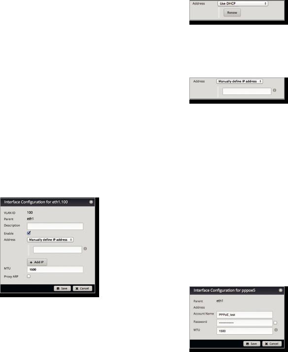
Configure the VLAN
After you click Config, the Interface Configuration screen appears.
Make changes as needed.
•VLAN ID The VLAN ID is displayed.
•Parent The interface belonging to this VLAN is displayed.
•Description Enter keywords to describe this interface.
•Enable Check the box to enable the VLAN. All of the VLANs are saved in the system configuration file; however, only the enabled VLANs are active on the device.
•Address Select one of the following:
-- No address The interface uses no address settings. (In most cases, an address is needed.)
Chapter 3: Dashboard
-- Use DHCP The interface acquires network settings from a DHCPv4 server. Click the Renew button to acquire fresh network settings.
-- Use DHCP for IPv6 The interface acquires network settings from a DHCPv6 server.
-- Manually define IP address(es) Enter the static IP address (example: 192.0.2.1/24 for IPv4 or
2001:db8::1/32 for IPv6).
-- Add IP Click Add IP to enter additional IP addresses.
•MTU Enter the MTU (Maximum Transmission Unit) value, which is the maximum packet size (in bytes) that a network interface can transmit. For the ER X, ER X SFP, and EP R6, the valid MTU range is 68 to 2018. For all other models, the valid MTU range is 68 to 9000. The default is 1500.
•Proxy ARP Enable the EdgeRouter to answer a source host’s ARP (Address Resolution Protocol) requests for the IP address of a destination host that is not located on the source host’s network. ARP allows hosts on the same network to discover each other’s IP address via a layer 2 broadcast to all MAC addresses. If they are not on the same network, the layer 2 broadcast will not reach its destination; however, the EdgeRouter can serve as the go-between if Proxy ARP is enabled.
Click Save to apply your changes, or click Cancel.
Configure PPPoE
After you click Config, the Interface Configuration screen appears.
Make changes as needed.
•PPPoE ID The PPPoE ID is displayed.
•Address The IP address is displayed.
•Account Name Enter the username to connect to the PPPoE server; this must match the username configured on the PPPoE server.
Ubiquiti Networks, Inc. |
13 |

Chapter 3: Dashboard
•Password Enter the password to connect to the PPPoE server; this must match the password configured on the PPPoE server. Check the box to display the password.
•MTU Enter the MTU (Maximum Transmission Unit) value, which is the maximum packet size (in bytes) that a network interface can transmit. The valid MTU range is 68 to 1500. The default is 1492.
Note: Setting the MTU higher than 1492 will require ISP support and also require increasing the MTU value of the parent interface (ethX) accordingly.
Click Save to apply your changes, or click Cancel.
Configure the Switch (EdgeRouter PoE)
The switch configuration is available for EdgeRouter PoE, EdgeRouter X, EdgeRouter X SFP, and EdgePoint EP-R6 only. This section covers the options for the EdgeRouter PoE only. Proceed to the Configure the Switch (EdgeRouter X Platform) section in the next column for the other models.
After you click Config, the Interface Configuration screen appears.
Make changes as needed.
•Description Enter keywords to describe this switch.
•Address Select one of the following:
-- No address The switch uses no address settings. (In most cases, an address is needed.)
-- Use DHCP The switch acquires network settings from a DHCPv4 server. Click the Renew button to acquire fresh network settings.
-- Use DHCP for IPv6 The switch acquires network settings from a DHCPv6 server.
-- Manually define IP address(es) Enter the static IP address (example: 192.0.2.1/24 for IPv4 or 2001:db8::1/32 for IPv6). Click Add IP to enter additional IP addresses.
EdgeOS User Guide
•Switch Ports Select the ports for the switch interface.
•Proxy ARP Enable the EdgeRouter to answer a source host’s ARP (Address Resolution Protocol) requests for the IP address of a destination host that is not located on the source host’s network. ARP allows hosts on the same network to discover each other’s IP address via a layer 2 broadcast to all MAC addresses. If they are not on the same network, the layer 2 broadcast will not reach its destination; however, the EdgeRouter can serve as the go-between if Proxy ARP is enabled.
Click Save to apply your changes, or click Cancel.
Configure the Switch (EdgeRouter X Platform)
(Available for the EdgeRouter X, EdgeRouter X SFP, and EdgePoint EP-R6 only.) After you click Config, the Interface Configuration screen appears.
Make changes as needed. There are two tabs: Config and VLAN.
Config
•Description Enter keywords to describe this switch.
•Address Select one of the following:
-- No address The switch uses no address settings. (In most cases, an address is needed.)
-- Use DHCP The switch acquires network settings from a DHCPv4 server. Click the Renew button to acquire fresh network settings.
-- Use DHCP for IPv6 The switch acquires network settings from a DHCPv6 server.
-- Manually define IP address(es) Enter the static IP address (example: 192.0.2.1/24 for IPv4 or 2001:db8::1/32 for IPv6). Click Add IP to enter additional IP addresses.
•Add IP Click to add another IP address.
14 |
Ubiquiti Networks, Inc. |
EdgeOS User Guide
•Proxy ARP Enable the EdgeRouter to answer a source host’s ARP (Address Resolution Protocol) requests for the IP address of a destination host that is not located on the source host’s network. ARP allows hosts on the same network to discover each other’s IP address via a layer 2 broadcast to all MAC addresses. If they are not on the same network, the layer 2 broadcast will not reach its destination; however, the EdgeRouter can serve as the go-between if Proxy ARP is enabled.
Click Save to apply your changes, or click Cancel.
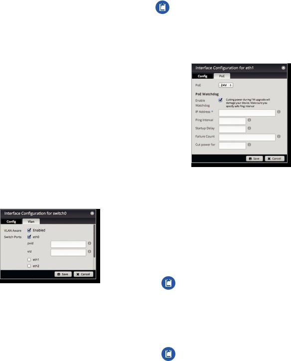
VLAN
•VLAN Aware Starting with EdgeOS v1.8.5, the per-port VLAN feature is available. If this option is enabled, then untagged and tagged VLANS can be set for each port in switch mode. If this option is kept disabled (default), then the switch ports will pass all VLANs automatically (simple layer-2 switching with no per-port VLAN).
•Switch Ports Select the ports for the switch interface.
-- pvid If VLAN Aware is enabled, then this option is available. Enter the Port Virtual Local Area Network (VLAN) ID. The valid range is 1 to 4087.
-- vid If VLAN Aware is enabled, then this option is available. Enter the Virtual Local Area Network (VLAN) ID. Multiple VIDs are allowed; separate the VIDs with a comma. The valid range is 1 to 4087.
Click Save to apply your changes, or click Cancel.
Chapter 3: Dashboard
Configure the PoE Settings
Note: Before enabling PoE, check the specifications of your airFiber, airMAX, UniFi, UniFi Video, legacy, or third party devices to ensure they support passive PoE and require the available amount of voltage.
(Available for the EdgePoint EP-R6, EdgePoint EP-R8, or EdgeRouter PoE only.) After you click PoE, the PoE tab of the Interface Configuration screen appears.
PoE is disabled by default on all ports. Follow the instructions for your model:
•EdgeRouter X (below)
•EdgePoint EP-R6/EdgeRouter X SFP (below)
•“EdgePoint EP-R8” on page 16
•“EdgeRouter PoE” on page 16
EdgeRouter X
Only eth4 supports PoE passthrough.
•PoE Select one of the following: -- Off To disable PoE, select Off.
Note: To disable PoE, you must use this setting. If you disable a port, its PoE functionality remains.
-- Passthrough To allow passive PoE pass through, select Passthrough.
EdgePoint EP-R6/EdgeRouter X SFP
•PoE Select one of the following: -- Off To disable PoE, select Off.
Note: To disable PoE, you must use this setting. If you disable a port, its PoE functionality remains.
-- 24V To output 24V, 2-pair PoE to the connected device, select 24V.
Ubiquiti Networks, Inc. |
15 |
Chapter 3: Dashboard
EdgePoint EP-R8
•PoE Select one of the following: -- Off To disable PoE, select Off.
Note: To disable PoE, you must use this setting. If you disable a port, its PoE functionality remains.
-- 24V-4pair (Available for eth1-2 only) To output 24V, 4-pair PoE to the connected device, select 24V-4pair.
-- 54V-4pair (Available for eth1-2 only) To output 54V, 4-pair PoE to the connected device, select 54V-4pair.
-- 24V (Available for eth3-7 only) To output 24V, 2-pair PoE to the connected device, select 24V.
EdgeRouter PoE
•PoE Select one of the following: -- Off To disable PoE, select Off.
Note: To disable PoE, you must use this setting. If you disable a port, its PoE functionality remains.
-- 24V To output 24V PoE to the connected device, select 24V.
-- 48V To output 48V PoE to the connected device, select 48V.
Note: You must have a 48V power adapter (not included) powering the EdgeRouter PoE; otherwise, 48V PoE is not allowed.
PoE Watchdog
PoE Watchdog is only for PoE-enabled ports. It configures the device to continuously ping a user-defined IP address (it can be the Internet gateway, for example). If it is unable to ping under the user-defined constraints, then the device will automatically turn off PoE on the port, and then turn it back on. This option creates a kind of “fail proof” mechanism.
PoE Watchdog is dedicated to continuous monitoring of the specific connection to the remote host using the Ping tool. The Ping tool works by sending ICMP echo request packets to the target host and listening for ICMP echo response replies. If the specified number of replies is not received, the tool reboots the device.
•Enable Watchdog Enable the use of PoE Watchdog.
-- IP Address To Ping Specify the IPv4 or IPv6 address of the target host to be monitored by PoE Watchdog.
-- Ping Interval Specify the time interval (in seconds) between the ICMP echo requests that are sent by PoE Watchdog. The default value is 15 seconds.
-- Startup Delay Specify the initial time delay (in seconds) until the first ICMP echo requests are sent by PoE Watchdog. The default value is 300 seconds.
The Startup Delay value should be at least 60 seconds as the network interface and wireless connection initialization takes a considerable amount of time if the device is rebooted.
EdgeOS User Guide
-- Failure Count Specify the number of ICMP echo response replies. If the specified number of ICMP echo response packets is not received continuously, PoE Watchdog will reboot the device. The default value
is 3.
-- Cut power for Specify the number of seconds this port should pause PoE (if applicable). The default value is 5.
WARNING: Cutting power during a firmware upgrade can damage your device. Ensure that you specify a safe Ping Interval.
Click Save to apply your changes, or click Cancel.
16 |
Ubiquiti Networks, Inc. |
EdgeOS User Guide
Chapter 4: Traffic Analysis
The Traffic Analysis tab displays status information about the traffic traveling through the EdgeRouter, including the local hosts and types of network traffic. You can also configure the application category options. Any setting marked with a blue asterisk * is required. When the information  icon is displayed, you can click the icon for more information about an option.
Starting with EdgeOS v1.7, the traffic analysis feature with Deep Packet Inspection (DPI) is available for the
EdgeRouter Lite, EdgeRouter PoE, EdgeRouter, EdgeRouter PRO, and EdgePoint EP-R8.
Starting with EdgeOS v1.8.5, the traffic analysis feature with DPI is also available for the EdgeRouter X, EdgeRouter X SFP, and EdgePoint EP-R6.
DPI is more advanced than conventional Stateful Packet Inspection (SPI) filtering. Ubiquiti’s advanced, proprietary DPI engine includes the latest application identification signatures to track which applications (and IP addresses) are using the most bandwidth.
The traffic analysis feature provides monitoring and reporting functionality. There are no licensing fees for DPI or signature updates, which are automatically updated on a periodic basis to maintain the accuracy of application identification.
Click the corresponding open/close tab to hide or display the Traffic Analysis section, the Top Hosts section, or both the Top Hosts and Category sections.
Ubiquiti Networks, Inc.
Chapter 4: Traffic Analysis
Open/Close Tab
Open/Close Tab
Open/Close Tab 
Traffic Analysis
Clear Data Click to clear the current traffic statistics. Operational Status You have three options:
•Enabled Select this option to allow traffic analysis with application identification using DPI. All forwarded traffic (both offloaded and non-offloaded) is displayed.
•Hosts only Select this option to analyze traffic at the host level only, without DPI.
•Disabled Disabled by default.
17
Chapter 4: Traffic Analysis
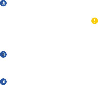
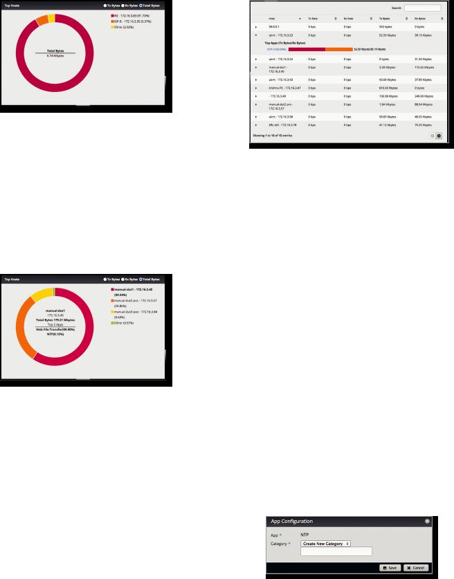
Top Hosts
The pie chart represents the use of bandwidth by the hosts using the most bandwidth.
TX Bytes Displays the transmit bandwidth in bytes used by the top hosts.
RX Bytes Displays the receive bandwidth in bytes used by the top hosts.
Total Bytes Displays the total bandwidth in bytes used by the top hosts.
The list on the right displays the top hosts and their percentages of bandwidth use.
Place the mouse over a host’s segment of the pie chart, and that host’s top applications will be displayed in the middle of the pie chart. Click the host’s segment to automatically select the host in the table.
18
EdgeOS User Guide
Hosts
Each row corresponds to a single host. Click a row to display the applications usage of a specific host.
Search Allows you to search for specific text within the host table. Begin typing; there is no need to press enter. The results are filtered in real time as soon as you type two or more characters.
Host Displays the host name and IP address. TX Rate Displays the transmit rate.
RX Rate Displays the receive rate.
TX Bytes Displays the amount of data transmitted. RX Bytes Displays the amount of data received. Click any row to display the applications usage.
•Top Apps (TX Bytes/RX Bytes) Displays the following:
-- (name) Click the application name to add it to a custom category or create a custom category. Go to the Application Category section below.
-- (_%) Each application’s usage is represented as a percentage of the host’s bandwidth.
-- (bar graph) The TX and RX usage of an application is represented in a bar graph.
-- (TX/RX) The TX and RX bytes of an application are displayed.
Application Category
The App Configuration screen appears.
•App The name of the application is displayed.
•Category If the category already exists, then select it from the drop-down menu. Otherwise, select Create New Category and enter the name of the new category in the field below.
Click Save to apply your changes or click Cancel.
Ubiquiti Networks, Inc.
EdgeOS User Guide
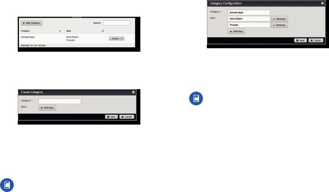
Category
You can create custom application categories for use in firewall policies. This allows a firewall to match packets that are identified by DPI as certain applications. (Refer to ”Advanced” on page 31 for more information.)
Add Category To create a new category, click Add Category.
The Create Category screen appears.
Complete the following:
•Category Enter a name for this category.
•Apps Click Add App to add an application. Then enter the name of the application. (An application can only appear in a single custom category.)
Note: The name of the application must match one of the applications displayed on the Traffic Analysis tab.
•Remove Click Remove to delete an application. Click Save to apply your changes or click Cancel.
Search Allows you to search for specific text within the category table. Begin typing; there is no need to press enter. The results are filtered in real time as soon as you type two or more characters.
Category The name of the custom category is displayed.
Apps The names of the included applications are displayed.
Actions Click the Actions button to access the following options:
•Config To configure the category, click Config. Go to the Configure the Category section in the next column.
•Delete Remove the category.
Chapter 4: Traffic Analysis
Configure the Category
After you click Config, the Category Configuration screen appears.
•Category You can change the name for this category.
•Apps Click Add App to add an application. Then enter the name of the application. (An application can only appear in a single custom category.)
Note: The name of the application must match one of the applications displayed on the Traffic Analysis tab.
•Remove Click Remove to delete an application. Click Save to apply your changes or click Cancel.
Ubiquiti Networks, Inc. |
19 |
Chapter 4: Traffic Analysis |
EdgeOS User Guide |
20 |
Ubiquiti Networks, Inc. |

EdgeOS User Guide
Chapter 5: Routing
The Routing tab displays status information about a variety of connected, static, RIP, and OSPF routes. You can also configure static routes and OSPF options. Any
setting marked with a blue asterisk * is required. When the information  icon is displayed, you can click the icon for more information about an option.
You have two sub-tabs:
Routes View route information and create static routes. OSPF Configure OSPF options.
IPv6 Routing
IPv6 (Internet Protocol version 6) is gaining popularity and is bound to grow as IP addressing demands increase. The EdgeOS Configuration Interface supports IPv6 for the following options:
•System > Name Server configuration (Refer to “Name Server” on page 5.)
•Dashboard > VLAN creation
(Refer to “Add VLAN” on page 11.)
•Dashboard > Interface configuration
(Refer to “Configure the Interface” on page 12.)
•Dashboard > VLAN configuration
(Refer to “Configure the VLAN” on page 13.)
•VPN > IPsec Site-to-Site configuration (Refer to “IPsec Site-to-Site” on page 46.)
Chapter 5: Routing
•Config Tree
(Refer to “Config Tree” on page 63.)
For IPv6 addresses, the EdgeOS Configuration Interface supports “::” (double colon) notation, which substitutes “::” for a contiguous sequence of 16-bit blocks set to zero. Here is an example: 2001:db8::1
If written out, the IPv6 address becomes:
2001:db8:0000:0000:0000:0000:0000:0001
The EdgeOS Configuration Interface displays IPv6 addresses only in three locations:
•System > Name Server section
•Dashboard tab
•VPN > IPsec Site-to-Site tab
The EdgeOS Configuration Interface will increase its support of IPv6 in future releases. For other options, you can use the config tree or CLI, which has comprehensive IPv6 support.
Note: Use the config tree or CLI to view or configure IPv6 options that are not supported by the rest of the EdgeOS Configuration Interface.
Ubiquiti Networks, Inc. |
21 |
Chapter 5: Routing
Routes
A route determines how traffic travels to its destination network. If more than one route is suitable, the EdgeRouter uses administrative distance as a metric to compare all available routes, including directly connected routes, manually configured static routes, dynamic routes, and the default route. The EdgeRouter uses the route with the lowest administrative distance.
All/Static/Connected/RIP/OSPF
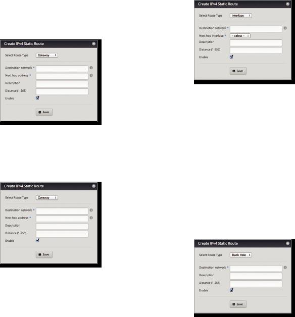
Add Static Route To create a new static route, click Add Static Route.
The Create Static Route screen appears.
Complete the following:
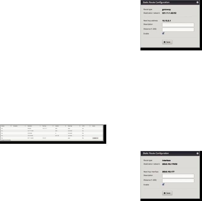
•Select Route Type You have three options: Gateway,
Interface, or Black Hole.
-- Gateway Define a route using the IP address and subnet mask of the next hop gateway.
•Destination network Enter the IP address and subnet mask using slash notation:
<network_IP_address>/<subnet_mask_number> (example: 192.0.2.0/24).
The first default route is configured on the System tab; see “System gateway address” on page 5 for more information. To create multiple default routes, set up static routes and enter 0.0.0.0/0.
•Next hop address Enter the IP address.
•Description Enter keywords to identify this route.
EdgeOS User Guide
•Distance (1-255) Enter the administrative distance. If there are identical routes from different sources (such as static, RIP, or OSPF), the EdgeRouter compares the routes and uses the route with the lowest distance.
•Enable Check the box to enable the route.
Click Save to apply your changes.
-- Interface Define a route using a next hop interface.
•Destination network Enter the IP address and subnet mask using slash notation:
<network_IP_address>/<subnet_mask_number> (example: 192.0.2.0/24).
•Next hop interface Select the appropriate interface from the drop-down list.
•Description Enter keywords to identify this route.
•Distance (1-255) Enter the administrative distance. If there are identical routes from different sources (such as static, RIP, and OSPF), the EdgeRouter compares the routes and uses the route with the lowest distance.
•Enable Check the box to enable the route.
Click Save to apply your changes.
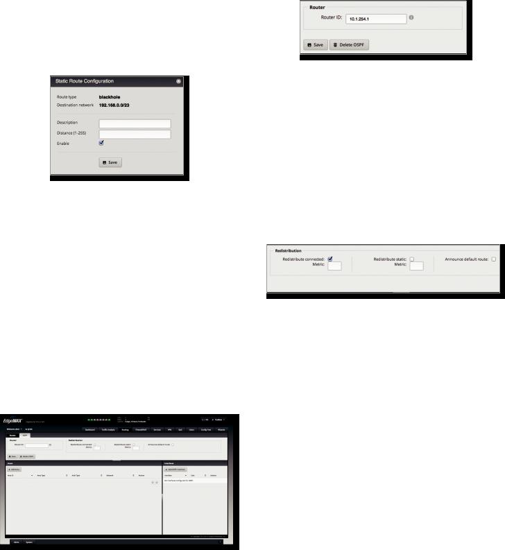
-- Black Hole Define a route that drops unwanted traffic.
•Destination network Enter the IP address and subnet mask using slash notation:
<network_IP_address>/<subnet_mask_number> (example: 192.0.2.0/24).
•Description Enter keywords to identify this route.
22 |
Ubiquiti Networks, Inc. |
EdgeOS User Guide
•Distance (1-255) Enter the administrative distance. If there are identical routes from different sources (such as static, RIP, and OSPF), the EdgeRouter compares the routes and uses the route with the lowest distance.
•Enable Check the box to enable the route.
Click Save to apply your changes.
Search Allows you to search for specific text. Begin typing; there is no need to press enter. The results are filtered in real time as soon as you type two or more characters.
All/Static/Connected/RIP/OSPF Click the appropriate tab to filter the routes as needed.
•All All routes are displayed by default.
•Static All static routes that you have configured are displayed.
•Connected All routes that are directly connected to the EdgeRouter are displayed.
•RIP All RIP (Routing Information Protocol) routes are displayed. RIP is an interior, distance vector routing protocol that uses hop count as a metric to determine the best route.
•OSPF All OSPF (Open Shortest Path First) routes are displayed. OSPF is an interior, link-state routing protocol that uses cost as a metric to determine the best route. The bandwidth of an interface determines the cost – the higher the bandwidth, the lower the cost.
A table displays the following information about each route. Click a column heading to sort by that heading.
Selected The status of the route, whether it has been selected for the routing table, is displayed.
Description If available, the keywords describing the route are displayed.
Destination The destination IP address is displayed.
Next Hop The IP address of the next-hop interface is displayed.
Interface The name of the interface is displayed. Route Type The type of route is displayed.
In FIB The forwarding status of the route, whether it is in the FIB (Forwarding Information Base), is displayed.
Actions Click the Actions button to access the following options:
•Config To configure the route, click Config. Go to the
Configure the Static Route section in the next column.
•Delete Delete the route; its configuration will be removed.
Chapter 5: Routing
•Disable Disable the route while keeping its configuration. (This option is not available for black hole routes.)
Configure the Static Route
After you click Config, the Static Route Configuration screen appears.
Follow the instructions for your route type:
Gateway
•Route type The gateway route uses the IP address and subnet mask of the next hop gateway.
•Destination network The IP address and subnet mask are displayed in slash notation.
•Next hop address The IP address of the next hop gateway is displayed.
•Description Enter keywords to identify this route.
•Distance (1-255) Enter the administrative distance. If there are identical routes from different sources (such as static, RIP, and OSPF), the EdgeRouter compares the routes and uses the route with the lowest distance.
•Enable Check the box to enable the route. Click Save to apply your changes.
Interface
•Route type The interface route uses the next hop interface.
•Destination network The IP address and subnet mask are displayed in slash notation.
•Next hop interface The name of the next hop interface is displayed.
•Description Enter keywords to identify this route.
Ubiquiti Networks, Inc. |
23 |
Chapter 5: Routing
•Distance (1-255) Enter the administrative distance. If there are identical routes from different sources (such as static, RIP, and OSPF), the EdgeRouter compares the routes and uses the route with the lowest distance.
•Enable Check the box to enable the route. Click Save to apply your changes.
Black Hole
•Route type The black hole route drops unwanted traffic.
•Destination network The IP address and subnet mask are displayed in slash notation.
•Description Enter keywords to identify this route.
•Distance (1-255) Enter the administrative distance. If there are identical routes from different sources (such as static, RIP, and OSPF), the EdgeRouter compares the routes and uses the route with the lowest distance.
•Enable Check the box to enable the route. Click Save to apply your changes.
OSPF
Using Link State Advertisements, routers communicate with each other when there is a router or link status change. Each router maintains the information in a database, which is used to create and update a network map from the router’s point of view. Each router then uses the map to build and update a routing table.
EdgeOS User Guide
Router
Router ID Enter the IP address that identifies a specific router in an OSPF network. In OSPF, the highest Router ID determines which router is the Designated Router (DR), which distributes updates to the other OSPF routers.
Click Save to apply your changes, or click Delete OSPF to remove the Router, Redistribution, and Area settings (Interfaces settings are retained).
Redistribution
A single router can use multiple routing protocols, such as OSPF and RIP, which use incompatible metrics. It must reconcile information from multiple protocols to determine which route to use for a specific destination network. You can change the metrics of the distributed protocol to create protocol compatibility.
Redistribute connected If enabled, the EdgeRouter connects an OSPF area to a network using a different routing protocol and redistributes the other protocol’s directly connected routes into the OSPF area. These routes become external OSPF routes.
-- Metric If there are multiple routes to the same destination, OSPF uses the metric to select a route for the routing table. Assign a cost value to the redistributed connected routes. The EdgeRouter can then use this metric to compare these routes to other OSPF routes.
Redistribute static If enabled, the EdgeRouter connects an OSPF area to a network using a different routing protocol and redistributes the other protocol’s static routes into the OSPF area. These routes become external OSPF routes.
-- Metric If there are multiple routes to the same destination, OSPF uses the metric to select a route for the routing table. Assign a cost value to the redistributed static routes. The EdgeRouter can then use this metric to compare these routes to other OSPF routes.
Announce default route If enabled, the EdgeRouter communicates the default route to the other routers of the OSPF network, eliminating the need to configure the default route on the other routers. The default route connects the OSPF network to an outside network.
24 |
Ubiquiti Networks, Inc. |
EdgeOS User Guide
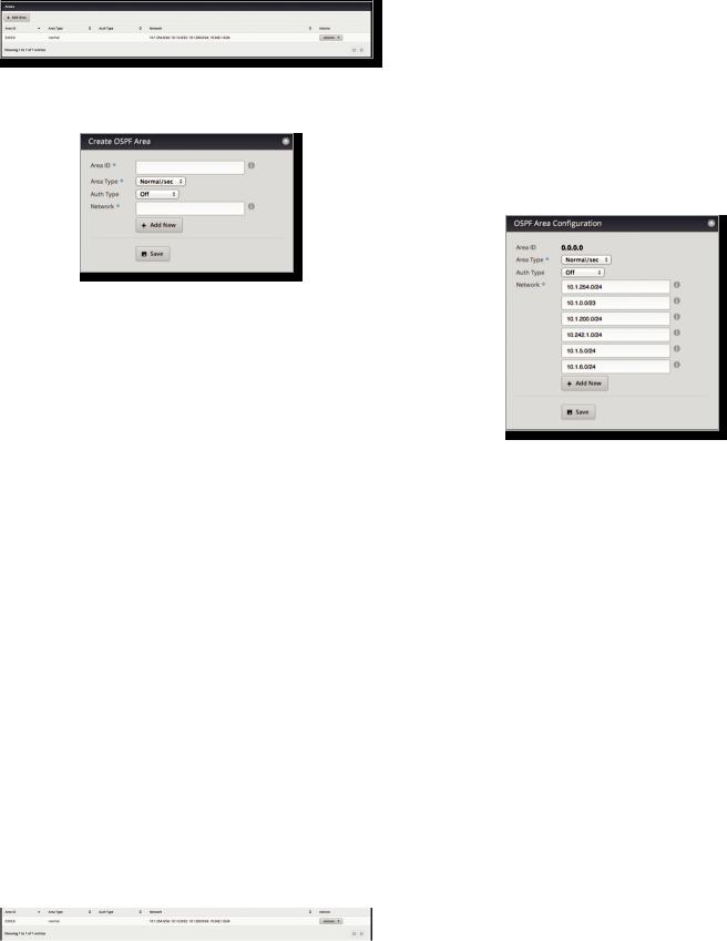
Areas
To enhance scalability, an OSPF network is comprised of smaller sections called areas. At the minimum, there is the backbone area, called Area 0.
Add Area To create a new area, click Add Area. The Create OSPF Area screen appears.
Complete the following:
•Area ID This is the number that identifies an area. It can be an integer or use a format similar to an IPv4 address.
•Area Type This defines the routes that are acceptable inside the area. Select the appropriate option:
-- Normal/sec The default type accepts all routes.
-- NSSA A NSSA (Not So Stubby Area) network is a variation of a stub network. It can import external routes from type 7 Link State Advertisements, which are NSSA-specific.
-- Stub The network has no external routes. Typically, it has a default route for outbound traffic.
•Auth Type Authentication helps secure communication between routers. Select the appropriate option:
-- Off No authentication is used.
-- MD5/sec Each router uses a key (password) and key ID. This is the most secure option because the key is never transmitted.
-- Plain text Each router uses a key. This provides minimal security because the key is transmitted in plain text format.
•Network Enter the IP address and subnet mask using slash notation:
<network_IP_address>/<subnet_mask_number> (example: 192.0.2.0/24).
Click Add New to enter more network addresses. Click Save to apply your changes.
A table displays the following information about each OSPF Area. Click a column heading to sort by that heading.
Chapter 5: Routing
Area ID The identification number of the area is displayed.
Area Type The type of area is displayed.
Auth Type The authentication type of the area is displayed.
Network The network address of the area is displayed.
Actions Click the Actions button to access the following options:
•Config To configure the OSPF Area, click Config. Go to the Configure the OSPF Area section.
•Delete Delete the OSPF Area.
Configure the OSPF Area
After you click Config, the OSPF Area Configuration screen appears.
Make changes as needed.
•Area ID This is the number that identifies an area. It can be an integer or use a format similar to an IPv4 address.
•Area Type This defines the routes that are acceptable inside the area. Select the appropriate option:
-- Normal/sec The default type accepts all routes.
-- NSSA A NSSA (Not So Stubby Area) network is a variation of a stub network. It can import external routes from type 7 Link State Advertisements, which are NSSA-specific.
-- Stub The network has no external routes. Typically, it has a default route for outbound traffic.
•Auth Type Authentication helps secure communication between routers. Select the appropriate option:
-- Off No authentication is used.
-- MD5/sec Each router uses a key (password) and key ID. This is the most secure option because the key is never transmitted.
-- Plain text Each router uses a key. This provides minimal security because the key is transmitted in plain text format.
|
|
|
|
|
|
Ubiquiti Networks, Inc. |
25 |
Chapter 5: Routing
•Network Enter the IP address and subnet mask using slash notation:
<network_IP_address>/<subnet_mask_number> (example: 192.0.2.0/24).
Click Add New to enter more network addresses. Click Save to apply your changes.
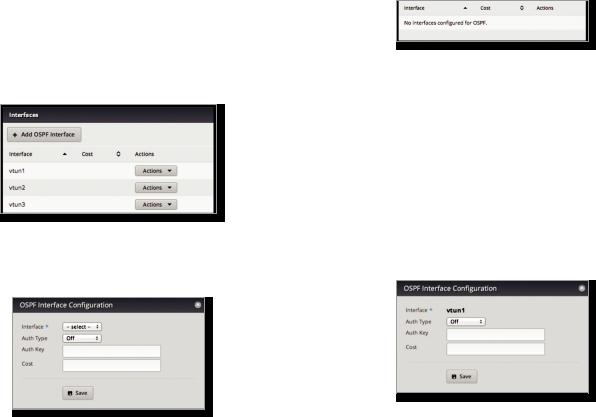
Interfaces
You can configure interfaces with specific OSPF options.
Add OSPF Interface To create a new interface, click Add OSPF Interface.
The OSPF Interface Configuration screen appears.
Complete the following:
•Interface Select the appropriate interface from the drop-down list.
•Auth Type OSPF authentication helps secure communication between routers. Select the appropriate option:
-- Off No authentication is used.
-- MD5/sec Each router uses a key (password) and key ID. This is the most secure option because the key is never transmitted.
-- Plain text Each router uses a key. This provides minimal security because the key is transmitted in plain text format.
•Auth Key Enter the key used for authentication.
•Cost By default, the cost of an interface is based on its bandwidth; however, you can manually assign a cost to the interface.
Click Save to apply your changes.
EdgeOS User Guide
A table displays the following information about each OSPF Interface. Click a column heading to sort by that heading.
Interface The name of the interface is displayed.
Cost The cost of the interface is displayed. OSPF uses cost as a metric to determine the best route.
Actions Click the Actions button to access the following options:
•Config To configure the OSPF Interface, click Config. Go to the Configure the OSPF Interface section.
•Delete Delete the OSPF Interface.
Configure the OSPF Interface
After you click Config, the OSPF Interface Configuration screen appears.
Make changes as needed.
•Interface The name of the interface is displayed.
•Auth Type Authentication helps secure communication between routers. Select the appropriate option:
-- Off No authentication is used.
-- MD5/sec Each router uses a key (password) and key ID. This is the most secure option because the key is never transmitted.
-- Plain text Each router uses a key. This provides minimal security because the key is transmitted in plain text format.
•Auth Key Enter the key used for authentication.
•Cost By default, the cost of an interface is based on its bandwidth; however, you can manually assign a cost to the interface.
Click Save to apply your changes.
26 |
Ubiquiti Networks, Inc. |
Loading...