


 RESET
RESET
Model: UC-CK
Introduction
Thank you for purchasing the Ubiquiti Networks® UniFi® Cloud Key. This Quick Start Guide is designed to guide you through installation and also includes warranty terms.
Package Contents
UniFi Cloud Key |
Ethernet Cable |
microSD Card |
Quick Start Guide |
(8 GB) |
|
System Requirement
Web Browser: Google Chrome (Other browsers may have limited functionality.)
TERMS OF USE: All Ethernet cabling runs must use CAT5 (or above). It is the professional installer’s responsibility to follow local country regulations, including operation within legal frequency channels, output power, indoor cabling requirements, and Dynamic Frequency Selection (DFS) requirements.
Network Topology Requirement
A DHCP-enabled network (for the UniFi Cloud Key to obtain an IP address)
UniFi Cloud Key
(UniFi Controller)
UAP-AC-HD UAP-AC-PRO
UAP-AC-M-PRO
US-16-150W
LAN
USG-PRO-4 WAN
(DHCP Server)
Internet
Remote Access to
UniFi Controller
Sample Network Diagram
All UniFi devices also support off-site management controllers. For setup details, see the User Guide on the website: www.ubnt.com/download/unifi

Hardware Overview
Front Panel LED
LED Color |
Status |
White |
Factory defaults. |
|
|
Flashing White |
Initializing. |
|
|
|
Device is busy; do not touch or |
Alternating |
unplug it. This usually indicates |
White/Blue |
that a process such as a firmware |
|
upgrade is taking place. |
Blue |
Device is working properly. |
|
|
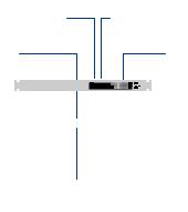
Top Panel
Ethernet Port
Ethernet This Gigabit Ethernet port is used to connect the power and should be connected to the
LAN and DHCP server. Power can be provided by an
802.3af PoE switch, such as the UniFi PoE Switch.
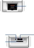
Bottom Panel
Reset Button
microSD Slot
USB Type C
Port
RESET
Reset The Reset button serves two functions:
•Restart Press and release the Reset button quickly.
•Restore to Factory Default Settings Press and hold the Reset button for more than five seconds.
USB-C Optional power source (5V, minimum 1A) if
PoE is not available.
microSD This slot is used to back up the Cloud Key configuration to the microSD card (included).

Side Panel
Shutdown
Button
Shutdown Press the Shutdown button to initiate a graceful shutdown (all services will be shut down and the CPU will remain active). After pressing the
button, wait until the LED goes off, and then unplug the Cloud Key.
Hardware Installation
1. Connect the Ethernet Cable to the Ethernet port.
2.Connect the other end of the Ethernet Cable to a port on a network switch, such as a UniFi Switch.
1 |
|
|
|
|
3 |
|
|
|
|
|
5 |
|
|
|
|
7 |
|
|
|
2 |
9 |
|
|
|
4 |
11 |
|
|
|
|
6 |
13 |
|
|
|
8 |
15 |
|
|
|
10 |
|
17 |
|
|
12 |
|
19 |
|
|
|
14 |
21 |
|
|
|
16 |
|
22 |
|
|
|
18 |
|
|
|
|
20 |
SFP1 |
|
|
|
22 |
|
|
|
|
|
24 |
|
|
|
|
SFP2 |

Powering the UniFi Cloud Key
Use an 802.3af-compliant switch, such as a UniFi
Switch, or a USB power source (not included).
UniFi Switch
The UniFi Cloud Key can be powered by a UniFi PoE
Switch or other 802.3af-compliant switch.
|
15 |
|
|
|
17 |
|
|
19 |
|
|
21 |
|
16 |
22 |
|
|
18 |
1 |
|
20 |
3 |
|
22 |
5 |
|
24 |
|
7 |
|
2 |
9 |
|
4 |
11 |
|
6 |
13 |
|
|
8 |
|
|
10 |
|
|
12 |
|
|
14 |
|
SFP1
SFP2
UniFi Switch Power Connection Diagram

USB Power Source
Connect the USB cable (not included) from the
UniFi Cloud Key directly to a USB power source
(5V, minimum 1A).
USB Power Connection Diagram
Software Installation
The UniFi Controller software is pre-installed on the UniFi Cloud Key. Use one of the following methods to launch the software:
•If you are using Chrome, go to the Chrome Instructions section (recommended).
•If you are using a different web browser, go to the
Instructions for Other Web Browsers section.
 Loading...