


AC or DC Powered, Managed PoE+ Gigabit Switch with SFP
Model: ES-8-150W
Introduction
Thank you for purchasing the Ubiquiti Networks® EdgeSwitch™. This Quick Start Guide is designed to guide you through the installation and also includes the warranty terms.
Package Contents
EdgeSwitch ES-8-150W
Power Cord |
Mount Brackets |
Bracket Screws |
|
(Qty. 2) |
(M4, Qty. 8) |
Mounting Screws |
Screw Anchors |
Quick Start |
(M4, Qty. 4) |
(M4, Qty. 4) |
Guide |
TERMS OF USE: All Ethernet cabling runs must use CAT5 (or above). It is the customer’s responsibility to follow local country regulations, including operation within legal frequency channels, output power, indoor cabling requirements, and Dynamic Frequency Selection (DFS) requirements.

System Requirements
•Linux, Mac OS X, or Microsoft Windows 7/8/10
•Web Browser: Mozilla Firefox, Google Chrome, Microsoft Edge, or Microsoft Internet Explorer 11
Installation Requirements
•Phillips screwdriver (for shelf or wall mounting)
•(Optional) 42 to 56VDC power source, such as the EdgePower™ EP-54V-150W, for stand alone DC power or redundant power backup.
•For indoor applications, use Category 5 (or above) UTP cabling approved for indoor use.
•For outdoor applications, shielded Category 5 (or above) cabling should be used for all wired Ethernet connections and should be grounded through the AC ground of the power supply.
We recommend that you protect your networks from harmful outdoor environments and destructive ESD events with industrial grade, shielded Ethernet cable from Ubiquiti Networks. For more details, visit www.ubnt.com/toughcable
WARNING: To reduce the risk of fire or electric shock, do not expose the switch to rain or moisture.
Note: Although the cabling can be located outdoors, the EdgeSwitch itself should be housed inside a protective enclosure.

Hardware Overview
LEDs
RJ45
PoE Link/Speed/Activity
|
|
|
|
|
|
|
|
|
|
|
|
|
|
|
|
|
|
|
|
|
|
|
|
|
|
|
|
|
|
|
|
|
|
|
|
|
|
|
|
|
|
|
|
|
|
|
|
|
|
|
|
|
|
|
|
|
|
|
|
|
|
|
|
|
|
|
|
|
|
|
|
|
|
|
|
|
|
|
|
|
|
|
|
System |
|
|
|
|
|
|
|
|
|
|
|
|
|
|
|
SFP |
||||
|
|
|
|
|
|
|
|
|
|
|
|
|
|
|
|
Link/Speed/Activity |
||||
RJ45 LEDs
LED |
State |
Status |
|
|
|
|
Off |
No PoE |
|
|
|
PoE |
Amber |
IEEE 802.3af/802.3at |
|
|
|
|
Green |
24V Passive |
|
|
|
|
Off |
No Link |
|
|
|
|
|
Link Established at |
Link/ |
Amber |
10/100 Mbps |
Speed/ |
|
Flashing Indicates Activity |
Activity |
|
|
|
Link Established at |
|
|
|
|
|
Green |
1000 Mbps (1 Gbps) |
|
|
Flashing Indicates Activity |
|
|
|

System LED
State |
Status |
|
|
Steady Blue |
Initializing. |
|
|
Flashing Blue |
Resetting to factory defaults. |
|
|
Steady White |
Ready for use and working properly. |
|
|
SFP LEDs
LED |
State |
Status |
|
|
|
|
|
Link/ |
Off |
No Link |
|
|
|
||
Speed/ |
|
Link Established at 1 Gbps |
|
Activity |
Green |
||
Flashing Indicates Activity |
|||
|
|
||
|
|
|

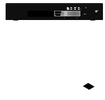
Front Panel
|
|
|
|
|
|
|
RJ45 1-8 |
SFP 1-2 |
|||||||||||||
|
|
|
|
|
|
|
|
|
|
|
|
|
|
|
|
|
|
|
|
|
|
|
|
|
|
|
|
|
|
|
|
|
|
|
|
|
|
|
|
|
|
|
|
|
|
|
|
|
|
|
|
|
|
|
|
|
|
|
|
|
|
|
|
|
|
|
|
|
|
|
|
|
|
|
|
|
|
|
|
|
|
|
|
|
|
|
|
|
|
|
|
|
|
|
|
|
|
|
|
|
|
|
|
|
|
|
|
|
|
Reset Button
Port Description
|
RJ45 ports support 10/100/1000 Ethernet |
|
RJ45 1-8 connections and configurable Power over |
||
|
Ethernet (auto PoE+ or 24V Passive). |
|
SFP 1-2 |
Hot-swappable SFP ports support 1 Gbps |
|
connections. |
||
|
||
|
There are two methods to reset the EdgeSwitch |
|
|
to factory defaults: |
|
|
Runtime Reset (Recommended) |
|
|
The EdgeSwitch should be running after bootup |
|
|
is complete, and the System LED is white. Press |
|
|
and hold the Reset button. The EdgeSwitch |
|
|
will reboot, and the System LED becomes blue |
|
|
after three seconds. Continue to hold the |
|
Reset |
Reset button for about 15 seconds until the |
|
System LED flashes blue for two seconds. This |
||
Button |
||
indicates that the EdgeSwitch has reset to its |
||
|
||
|
factory defaults. |
|
Power-on Reset
1.Disconnect power from the EdgeSwitch.
2.Reconnect power while holding the Reset button for about 15 seconds until the System
LED flashes blue for two seconds. This indicates that the EdgeSwitch has reset to its factory defaults.

Back Panel
|
|
Console Port |
AC Power |
||||||||||
|
|
|
|
|
|
|
|
|
|
|
|
|
|
|
|
|
|
|
|
|
|
|
|
|
|
|
|
|
|
|
|
|
|
|
|
|
|
|
|
|
|
|
|
|
|
|
|
|
|
|
|
||||
|
|
|
|
|
DC Input |
Ground |
|
|
|||||
|
|
|
|
|
|
||||||||
|
|
|
|
|
|
||||||||
Port |
Description |
|
|
|
|
||||||||
|
|
||||||||||||
|
RJ45 serial console port for Command |
||||||||||||
|
Line Interface (CLI) management. Use an |
||||||||||||
|
RJ45 to-DB9, serial console cable, also |
||||||||||||
|
known as a rollover cable, to connect |
||||||||||||
|
the Console port to your computer. Then |
||||||||||||
Console |
configure the following settings as needed: |
||||||||||||
• |
Baud rate 115200 |
|
|
|
|
||||||||
|
|
|
|
|
|||||||||
|
• |
Data bits 8 |
|
|
|
|
|||||||
|
• Parity NONE |
|
|
|
|
||||||||
|
• |
Stop bits 1 |
|
|
|
|
|||||||
|
• Flow control NONE |
|
|
|
|
||||||||
|
|
||||||||||||
AC Power |
Connect the included Power Cord to the AC |
||||||||||||
Power port. |
|
|
|
|
|||||||||
|
|
|
|
|
|||||||||
|
|
||||||||||||
|
Optional DC input for connecting a |
||||||||||||
DC Input |
redundant or stand alone 42 to 56VDC |
||||||||||||
power source, such as the EdgePower |
|||||||||||||
|
|||||||||||||
|
EP-54V-150W. |
|
|
|
|
||||||||
|
|
||||||||||||
Ground |
Ground bonding point for an optional |
||||||||||||
ground wire. |
|
|
|
|
|||||||||
|
|
|
|
|
|||||||||
|
|
|
|
|
|
|
|
|
|
|
|
|
|
Note: The redundant DC power source may be used as a hot backup. The DC power source will provide continuous power in the event of an interruption or loss of AC power.
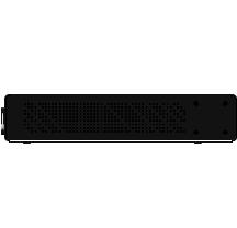
Side Panels
Ventilation Holes
WARNING: FAILURE TO PROVIDE PROPER VENTILATION MAY CAUSE FIRE HAZARD. KEEP AT LEAST 20 MM OF
CLEARANCE NEXT TO THE VENTILATION HOLES FOR
ADEQUATE AIRFLOW.
WARNING: The ES-8-150W must not be stacked. Do not place it on top of another switch. Do not place anything on top of the ES-8-150W.

Hardware Installation
The EdgeSwitch may be placed on a desktop, or mounted on a shelf or wall.
Shelf Mounting
1.Position the two Mount Brackets as shown below, and attach the brackets using the eight Bracket Screws.
2.Secure the EdgeSwitch to the shelf using the four
MountingScrews.
 Loading...