


Enterprise Gateway Router with Gigabit Ethernet
Model: USG
Introduction
Thank you for purchasing the Ubiquiti Networks® UniFi® Security Gateway. This Quick Start Guide is designed to guide you through installation and also includes warranty terms.
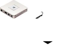
Package Contents
UniFi Security Gateway |
Power Adapter |
Power Cord |
|
(12V, 1A) |
|
|
|
Enterprise Gateway Router |
|
|
with Gigabit Ethernet |
Screws |
Screw Anchors |
Quick Start Guide |
(Qty. 2) |
(Qty. 2) |
|
TERMS OF USE: All Ethernet cabling runs must use CAT5 (or above). It is the professional installer’s responsibility to follow local country regulations and indoor cabling requirements.
UniFi Controller System Requirements
•Microsoft Windows 8, Mac OS X, or Linux
•Java Runtime Environment 1.6 (or above)
•Web Browser: Mozilla Firefox, Google Chrome, Microsoft Edge, or Microsoft Internet Explorer 11
•UniFi Controller software v5.4 or higher (available at: www.ubnt.com/download/unifi)
Network Requirements
A UniFi Cloud Key or management station running the UniFi
Controller software, located either on-site and connected to the same Layer-2 network, or off-site in the cloud or NOC
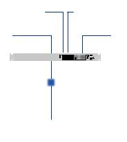
UniFi Cloud Key
(UniFi Controller)
UAP-AC-PRO UAP-AC-LR
UAP-AC-M-PRO
US-16-150W
LAN
USG
(DHCP Server)
WAN
Internet
Remote Access to
UniFi Controller
Sample Network Diagram
All UniFi devices support off-site management controllers. For setup details, see the User Guide on our website at: www.ubnt.com/download/unifi

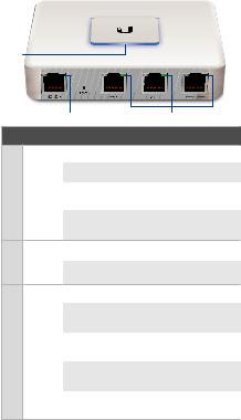
Hardware Overview
Ports Panel
Interface |
Description |
||
|
|
||
|
RJ45 serial console port for CLI management. |
||
|
Use a RJ45 to DB9 serial console cable to |
||
|
connect the Console port to your computer. |
||
|
Then configure using the following settings: |
||
Console |
• |
Baud rate 115200 |
|
|
• |
Data bits 8 |
|
|
• Parity NONE |
||
|
• |
Stop bits 1 |
|
|
• Flow control NONE |
||
|
|
||
|
Resets to factory defaults. The UniFi Security |
||
|
Gateway should be powered on. Press and hold |
||
|
the Reset button for about 10 seconds until |
||
Reset |
the right LED on the WAN 2 / LAN 2 port starts |
||
|
flashing and then becomes solidly lit. After a |
||
|
few seconds, the LED will turn off, and the UniFi |
||
|
Security Gateway will automatically reboot. |
||
|
|
||
WAN 1 |
Supports 10/100/1000 Ethernet WAN |
||
connections. Default setting is DHCP client. |
|||
|
|||
|
|
||
|
Supports 10/100/1000 Ethernet LAN |
||
LAN 1 |
connections. Default setting is DHCP Server. |
||
|
Server IP: 192.168.1.1/24 |
||
|
|
||
WAN 2 / |
Supports 10/100/1000 Ethernet connections. |
||
Configure the port using the UniFi Security |
|||
LAN 2 |
|||
Gateway configuration interface. |
|||
|
|||
|
|
|
|
LEDs
Status
Power |
Speed/Link/Act |
Ethernet Console Status Indicator
LED |
State |
Status |
|
|
White |
Fully Booted; Not Adopted |
|
|
|
|
|
|
Blue |
Adopted and Provisioned |
|
|
|
|
|
Status |
Alternating |
Device Firmware is |
|
|
White/Blue |
Upgrading |
|
|
|
|
|
|
Blue |
Device Locator Activated |
|
|
Flashing |
from UniFi Controller |
|
|
Off |
Power Off |
|
Power |
|
|
|
Green |
Power On |
||
|
|||
|
Off |
No Link |
|
|
|
|
|
|
Amber |
Link Established at |
|
|
10/100 Mbps |
||
|
|
||
|
|
|
|
Speed/ |
Amber |
Link Activity at |
|
Link/ |
Flashing |
10/100 Mbps |
|
Act |
|
|
|
Green |
Link Established at |
||
|
|||
|
1000 Mbps |
||
|
|
||
|
|
|
|
|
Green |
Link Activity at |
|
|
Flashing |
1000 Mbps |
|
|
|
|
Hardware Installation
The UniFi Security Gateway can be used on a level, stable surface, or mounted to a wall with the included screws and anchors. If you are not going to mount the UniFi Security
Gateway on a wall, then skip to the section, Connecting Power.
WARNING: To reduce the risk of fire or electric shock, do not expose this product to rain or moisture.
WARNING: FAILURE TO PROVIDE PROPER VENTILATION MAY CAUSE FIRE HAZARD. KEEP AT LEAST 20 MM OF CLEARANCE NEXT TO THE VENTILATION HOLES FOR ADEQUATE AIRFLOW.
Wall-Mounting
To mount the UniFi Security Gateway on a wall, you will need a drill, a 6 mm drill bit, and a Phillips screwdriver.
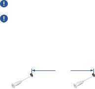
1.Use a 6 mm drill bit to drill two holes 90 mm apart. Insert a
Screw Anchor into each hole.
90 mm
*640-00120-04*
640-00120-04
2.Use a Phillips screwdriver to secure a Screw into each anchor. Leave a clearance of approximately 3 mm between the screw head and the wall.
3 mm
3.Position the UniFi Security Gateway over the Screws, and insert the Screws into the wall-mount slots located on the bottom of the UniFi Security Gateway. Then slide the UniFi
Security Gateway down to lock it into place.
12VDC

Connecting Power
1. Connect the Power Adapter to the power port.
2.Connect the Power Cord to the Power Adapter. Connect the other end of the Power Cord to a grounded power source.
 Loading...