


UniFi Switch 8
8-Port Managed Gigabit Switch
with 802.3af PoE
Model: US-8-60W
Introduction
Thank you for purchasing the Ubiquiti Networks® UniFi® 8-Port
Managed Gigabit Switch with 802.3af PoE. This Quick Start
Guide is designed to guide you through the installation and
also includes the warranty terms.
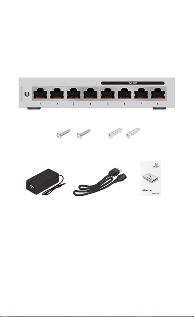
Package Contents
UniFi Switch
Mounting Screws
(Qty. 2)
Screw Anchors
(Qty. 2)
8-Port Managed Gigabit Switch
with 802.3af PoE
Model: US-8-60W
Power Adapter Power Cord Quick Start Guide
System Requirements
• Linux, MacOSX, or Microsoft Windows 7/8/10
• Java Runtime Environment 1.8 or above recommended
• Web Browser: Google Chrome (Other browsers may have
limited functionality)
• UniFi Controller software v5.3.x (or newer), available at:
www.ubnt.com/download/unifi
TERMS OF USE: All Ethernet cabling runs must use CAT5 (or above). It is the professional
installer’s responsibility to follow local country regulations, including operation within legal
frequency channels, output power, indoor cabling requirements, and Dynamic Frequency
Selection (DFS) requirements.
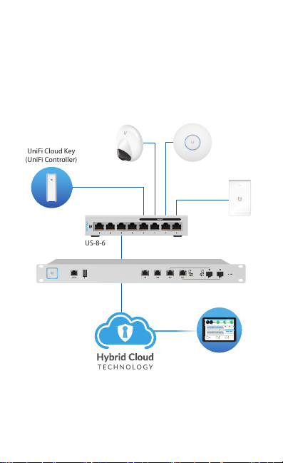
Network Topology Requirements
UAP-AC-IW
(UniFi Controller)
UniFi Controller
• A DHCP-enabled network for the UniFi Switch to obtain an
IPaddress (connected devices will also obtain IP addresses
after deployment)
• A UniFi Cloud Key or management station running the UniFi
Controller software v5.3 (or newer), located either on-site
and connected to the same Layer2 network, or off-site in a
cloud or NOC
UniFi Cloud Key
UAP-AC-PROUVC-G3-DOME
US-8-60W
USG-PRO-4
LAN
WAN
Internet
Sample Network Diagram
All UniFi devices support off-site management controllers.
For setup details, refer to the User Guide on the website:
www.ubnt.com/download/unifi
CURRENT SITE
USERNAME
Default
admin
25 22
547
597
2 118
WAN
LAN WLAN
2290.2
0.9 116
7 0.94 1
7
118
0.01 413
ACTIVE DEVICE
ACTIVE DEVICES
ACTIVE DEVICES
2.33
200+0 700+0
Inacve 0
Inacve 0
Inacve 0
msec Mbps
0
Pending 0
0
Pending
Pending
LATENCY THROUGHPUT
SPEED TEST
DOWNLOAD THROUGHPUT & LATENCY
DEVICES ON 2.4 GHZ CHANNEL
250
10
Latency [msec]
200
8
150
6
1 2 3 4 5 6 7 8 9 10 11
100
4
50
2
Throughput [Mbps]
DEVICES ON 5 GHZ CHANNEL
0
0
24 HRS 12 HRS NOW
Avg/Max Throughput Latency
UPLOAD THROUGHPUT & LATENCY
36 40 44 48 52 56 60 64
100
10
Latency [msec]
80
8
100 104 108 112 116 120 124 128
60
6
40
4
20
2
Throughput [Mbps]
132 136 140 144 149 153 157 161 165
0
0
24 HRS 12 HRS NOW
DEEP PACKET INSPECTIONCLIENTSDEVICES
258
582 GB
Motorola
Network Protocols
241
23.3 GB
Lenovo
Streaming Media
WLAN
118
220
22.7 GB
SamsungE
Web / Web 2.0
126
645 GB
1172
LAN
7
213
8.47 GB
Dell
File Transfer
DEVICES
TRAFFIC
CLIENTS
WAN
1
130
3.6 GB
Acer
Social Network
110
5.46 GB
Other
Other
Remote Access to
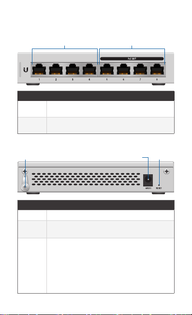
Hardware Overview
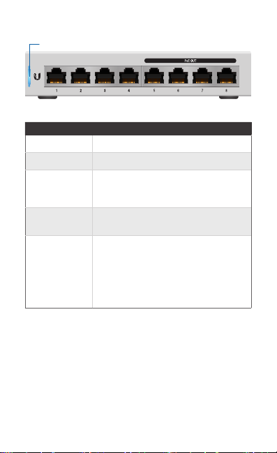
Front Panel
Port Description
1-4 RJ45 ports support 10/100/1000 Ethernet
5-8 RJ45 ports support 10/100/1000 Ethernet
Back Panel
Port Description
Ground Optional ancillary grounding point.
Power Connect the included Power Adapter to the
Reset
Button
Ports 1-4 Ports 5-8
connections.
connections and auto-sensing 802.3af PoE.
PowerGround
Power port.
This button serves two functions for the UniFi
Switch:
• Restart Press and release the Reset button
quickly.
• Restore to Factory Default Settings Press
and hold the Reset button for more than five
seconds.
Reset
Button
LEDs
System
System LED
State Status
Flashing White Initializing.
Steady White Factor y defaults, waiting for integration.
Alternating
White/Blue
Steady Blue Successfully integrated into a network
Flashing Blue This is used to locate a device.
Device is busy; do not touch or unplug it.
This usually indicates that a process such
as a firmware upgrade is taking place.
and working properly.
When you click Locate in the UniFi
Controller software, the System LED
will flash blue. The software will also
display the location of the UniFi Switch
on themap.
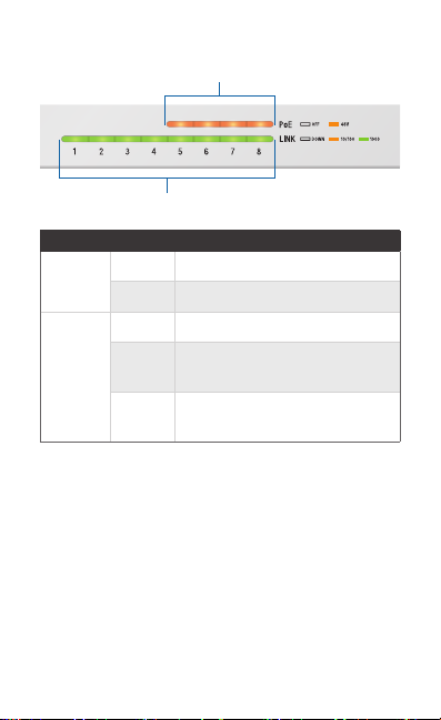
RJ45 LEDs
PoE
Link/Speed/Activity
LED
PoE
Link/
Speed/
Activity
State Status
Off PoE Off
Amber PoE On (IEEE 802.3af)
Off No Link
Link Established at 10/100Mbps
Amber
Flashing Indicates Activity
Link Established at 1 Gbps
Green
Flashing Indicates Activity
*640-00253-05*
640-00253-05
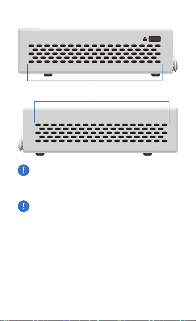
Side Panels
Ventilation Holes
WARNING: FAILURE TO PROVIDE PROPER VENTILATION
MAY CAUSE FIRE HAZARD. KEEP AT LEAST 20 MM OF
CLEARANCE NEXT TO THE VENTILATION HOLES FOR
ADEQUATE AIRFLOW.
WARNING: The US-8-60W must not be stacked. Do not
place it on top of another switch. Do not place anything
on top of the US-8-60W.
Hardware Installation
The UniFi Switch can be mounted on a vertical surface or
placed on a desktop. Follow the Wall Mounting instructions to
mount the switch using the included screws and anchors.
WARNING: To reduce the risk of fire or electric shock, do
not expose the switch to rain or moisture.
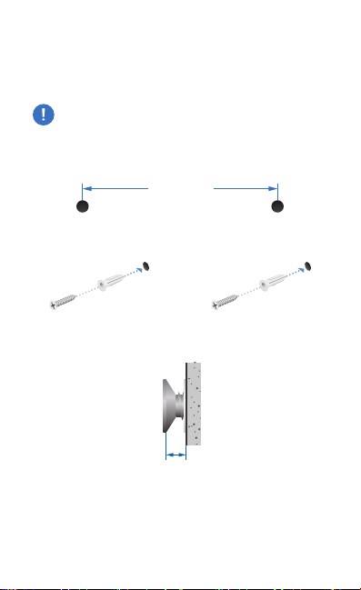
Wall Mounting
1. Drill two 6 mm holes set 73.5 mm apart.
73.5 mm
2. Insert a Screw Anchor into each hole, and fasten a Screw
into each anchor.
3. Leave a clearance of approximately 3mm between the
screw head and the wall.
3 mm
 Loading...