


2.4 GHz 2x2 MIMO
BaseStation
Sector Antenna
Model: AM-2G15-120

Introduction
Thank you for purchasing the Ubiquiti Networks™ airMAX®
2.4 GHz 2x2 MIMO BaseStation Sector Antenna. This Quick Start Guide is designed to guide you through the installation of the antenna. This Quick Start Guide also includes the warranty terms and is for use with the airMAX Sector Antenna, model AM-2G15-120.
Package Contents
Antenna Protective |
U-Brackets |
Pole Brackets |
Pole Clamps |
Shroud |
(Qty. 2) |
(Qty. 2) |
(Qty. 2) |
Carriage Bolts |
Serrated |
Serrated |
RF Cables |
Quick Start |
(M8x135, Qty. 4) |
Flange Bolts |
Flange Nuts |
(Qty. 2) |
Guide |
|
(M8x20, Qty. 4) |
(M8, Qty. 8) |
|
|
Products may be different from pictures and are subject to change without notice.
TERMS OF USE: Ubiquiti radio devices must be professionally installed. Shielded Ethernet cable and earth grounding must be used as conditions of product warranty. TOUGHCable™ is designed for outdoor installations. It is the customer’s responsibility to follow local country regulations, including operation within legal frequency channels, output power, and Dynamic Frequency Selection (DFS) requirements.

Installation Requirements
•Rocket™M2 (sold separately)
•12 mm and 13 mm wrenches
•Shielded Category 5 (or above) cabling should be used for all wired Ethernet connections and should be grounded through the AC ground of the PoE.
We recommend that you protect your networks from the most brutal environments and devastating ESD attacks with industrial grade shielded Ethernet cable from Ubiquiti Networks. For more details, visit www.ubnt.com/toughcable
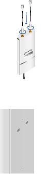
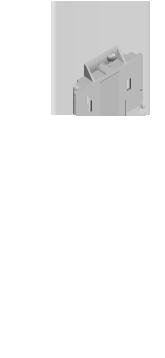
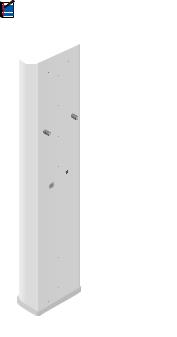
Hardware Overview
|
|
|
|
|
|
|
|
|
|
|
Slotted |
||||
Mounting |
|
|
|
|
U-Bracket |
||||||||||
Lugs |
|
|
|
|
|
|
|
|
|
|
|
|
|||
Bubble Level |
|
|
|
|
|
|
|
|
|
|
|
|
|
|
|
|
|
|
|
|
|
|
|
|
|
|
|
|
|||
RF Connectors |
|
|
|
|
|
Protective |
|
|
|||||||
|
|
|
|
|
|
|
|
||||||||
|
|
|
|
|
|
|
|
||||||||
|
|
|
|
|
|||||||||||
Rocket Mount |
|
|
|
|
|
Shroud |
|||||||||
|
|
|
|
|
|
|
|
|
|||||||
Bracket |
|
|
|
|
|
|
|
|
|
||||||
Rocket/Shroud |
|
|
|
|
|
|
|
|
|
||||||
|
|
|
|
|
|
|
|
|
|||||||
|
|
|
|
|
|
|
|
|
|||||||
Lock Release |
|
|
|
|
|
|
|
|
|
|
|||||
|
|
|
|
|
|
|
|
|
|
||||||
Lever |
|
|
|
|
|
|
|
|
|
||||||
|
|
|
|
|
|
|
|
|
|
|
U-Bracket |
|
|
||
Mounting |
|
|
|
|
|
|
|
|
|
|
|||||
Lugs |
|
|
|
|
|
|
|
|
|
||||||
Back View |
Assembled Side View |
|
Before Pole-Mounting |
Hardware Installation
1.Attach the RF Cables to the connectors labeled Chain 0 and
Chain 1 on the Rocket.
2.Attach the Rocket to the Rocket Mount Bracket.
a.Align the mounting tabs on the back of the Rocket with the four mounting slots on the bracket.
b.Slide the Rocket down until it locks into place.
3.Connect the other ends of the RF Cables to the RF Connectors on the antenna.
4.Slide the Protective Shroud down over the Rocket until it locks onto the Rocket Mount Bracket.
Note: If you have difficulty locking the shroud into place, try adjusting the placement of the RF Cables.
5.Attach the U-Brackets to the antenna:
a.Secure the Slotted U-Bracket to the upper Mounting Lugs of the antenna using two Serrated Flange Nuts.
b.Secure the other U-Bracket to the lower Mounting Lugs of the antenna using two Serrated Flange Nuts.
Note: Orient both U-Brackets as shown below.
 Loading...