


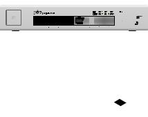
Managed PoE+ Gigabit Switch with SFP
Model: US-8-150W
Introduction
Thank you for purchasing the Ubiquiti Networks® UniFi® Switch. This Quick Start Guide is designed to guide you through the installation and also includes the warranty terms.
Package Contents
|
UniFi Switch |
|
Power Cord |
Mount Brackets |
Bracket Screws |
|
(Qty. 2) |
(M4, Qty. 8) |
Mounting Screws |
Screw Anchors |
Quick Start |
(M4, Qty. 4) |
(M4, Qty. 4) |
Guide |
System Requirements
•Linux, Mac OS X, or Microsoft Windows 7/8/10
•Java Runtime Environment 1.6 (1.8 or newer recommended)
•Web Browser: Mozilla Firefox, Google Chrome, Microsoft Edge, or Microsoft Internet Explorer 11
•UniFi Controller software v5 or above (recommended) or v4.8.x (offers possibly reduced feature set) available at: downloads.ubnt.com/unifi
TERMS OF USE: All Ethernet cabling runs must use CAT5 (or above). It is the customer’s responsibility to follow local country regulations, including operation within legal frequency channels, output power, indoor cabling requirements, and Dynamic Frequency Selection (DFS) requirements.
Network Topology Requirements
•A DHCP-enabled network for the UniFi Switch to obtain an
IP address (connected devices will also obtain IP addresses after deployment)
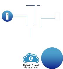
•A UniFi Cloud Key or management station running the UniFi Controller software v5 or above (recommended) or v4.8.x (possibly offering reduced feature set), located either on-site and connected to the same Layer 2 network, or off-site in a cloud or NOC
UniFi Cloud Key
(UniFi Controller)
UAP-AC-PRO UAP-AC-LR
UAP-IW
UniFi Switch US-8-150W
LAN
|
|
|
|
|
|
|
|
|
|
|
|
|
|
|
|
|
|
UniFi Security Gateway Pro |
WAN |
|
|
|
|
|
|
||||||||||
(DHCP Server) |
|
|
|
|
|
|
|
|
|
|
|
|
|
|
|||
|
|
|
|
|
|
|
|
|
|
|
|
|
|
|
|
|
|
|
|
|
|
Internet |
|
|
|
|
|
|
|||||||
|
|
|
|
|
|
|
|
|
|
|
|
|
|
|
|
|
|
|
|
|
|
|
|
|
|
|
|
|
|
|
|
|
|
|
|
|
|
|
|
|
|
|
|
|
|
|
|
|
|
|
|
|
|
|
|
|
|
|
|
|
|
|
|
|
|
|
|
|
|
|
|
|
|
|
|
|
|
|
|
|
|
|
|
|
|
|
|
|
|
|
|
|
|
|
|
|
|
|
|
|
|
|
|
|
|
|
|
|
|
|
|
|
|
|
|
|
|
|
|
|
|
|
|
|
|
|
|
|
|
|
|
|
|
|
|
|
|
|
|
|
|
|
|
|
|
|
|
|
|
|
|
|
|
|
|
|
|
|
|
|
|
|
|
|
|
|
|
|
|
|
|
|
|
|
|
|
|
|
|
|
|
|
|
|
|
|
|
|
|
|
|
|
|
|
|
|
|
Remote Access to
UniFi Controller
Sample Network Diagram
All UniFi devices support off-site management controllers. For setup details, refer to the User Guide on the website: documentation.ubnt.com/unifi
Hardware Overview
Front Panel
|
|
|
|
|
|
|
RJ45 1-8 |
SFP 1-2 |
||||||||||||
|
|
|
|
|
|
|
|
|
|
|
|
|
|
|
|
|
|
|
|
|
|
|
|
|
|
|
|
|
|
|
|
|
|
|
|
|
|
|
|
|
|
|
|
|
|
|
|
|
|
|
|
|
|
|
|
|
|
|
|
|
|
|
|
|
|
|
|
|
|
|
|
|
|
|
|
|
|
|
|
|
|
|
|
|
|
|
|
|
|
|
|
|
|
|
|
|
|
|
|
|
|
|
|
|
Reset Button
Port |
Description |
|
|
|
|
RJ45 1-8 |
RJ45 ports support 10/100/1000 Ethernet |
|
connections and Power over Ethernet (PoE). |
||
|
||
SFP 1-2 |
Hot-swappable SFP ports support 1 Gbps |
|
connections. |
||
|
||
|
This button serves two functions for the |
|
|
UniFi Switch: |
|
Reset |
• Restart Press and release the Reset button |
|
quickly. |
||
Button |
||
• Restore to Factory Default Settings Press |
||
|
||
|
and hold the Reset button for more than |
|
|
five seconds. |
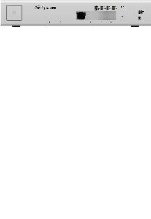
Back Panel
AC Power
Port |
Description |
AC Power |
Connect the included Power Cord to the AC |
|
Power port. |
||
|
||
|
|

LEDs
|
|
|
|
|
|
|
|
|
|
|
RJ45 |
|||||||||
System |
|
|
PoE |
|
|
Link/Speed/Activity |
||||||||||||||
|
|
|
|
|
|
|
|
|
|
|
|
|
|
|
|
|
|
|
|
|
|
|
|
|
|
|
|
|
|
|
|
|
|
|
|
|
|
|
|
|
|
|
|
|
|
|
|
|
|
|
|
|
|
|
|
|
|
|
|
|
|
|
|
|
|
|
|
|
|
|
|
|
|
|
|
|
|
|
|
|
|
|
|
|
|
|
|
|
|
|
|
|
|
|
|
|
|
|
|
|
|
|
|
|
|
|
|
|
|
|
|
|
|
|
|
|
|
|
|
|
|
|
|
|
|
|
|
|
|
|
|
|
|
|
|
|
|
|
|
|
|
|
|
|||
|
|
|
|
|
|
|
|
|
|
|
|
|
|
|
|
SFP |
||||
|
|
|
|
|
|
|
|
|
|
|
|
|
|
|
Link/Speed/Activity |
|||||
System LED |
|
|
|
|
|
|
|
|
|
|
|
|
|
|
|
|
|
|
||
|
|
|
|
|
|
|
|
|
|
|
|
|
|
|
||||||
State |
|
Status |
|
|
|
|
|
|
|
|
|
|
|
|
||||||
|
|
|
|
|
|
|
|
|
|
|
|
|
|
|
||||||
Flashing White |
|
Initializing. |
|
|
|
|
|
|
|
|
|
|
|
|
||||||
|
|
|
||||||||||||||||||
Steady White |
|
Factory defaults, waiting for integration. |
||||||||||||||||||
|
|
|
|
|
||||||||||||||||
Alternating |
|
Device is busy; do not touch or unplug it. |
||||||||||||||||||
|
This usually indicates that a process such |
|||||||||||||||||||
White/Blue |
|
|||||||||||||||||||
|
as a firmware upgrade is taking place. |
|||||||||||||||||||
|
|
|
|
|||||||||||||||||
|
|
|
|
|
||||||||||||||||
Steady Blue |
|
Successfully integrated into a network |
||||||||||||||||||
|
and working properly. |
|||||||||||||||||||
|
|
|
|
|||||||||||||||||
|
|
|
|
|
||||||||||||||||
|
|
|
|
This is used to locate a device. |
||||||||||||||||
|
|
|
|
When you click Locate in the UniFi |
||||||||||||||||
Flashing Blue |
|
Controller software, the System LED |
||||||||||||||||||
|
will flash blue. The software will also |
|||||||||||||||||||
|
|
|
|
|||||||||||||||||
|
|
|
|
display the location of the UniFi Switch |
||||||||||||||||
|
|
|
|
on the map. |
|
|
|
|
|
|
|
|
|
|
|
|
||||
|
|
|
|
|
|
|
|
|
|
|
|
|
|
|
|
|
|
|
|
|

RJ45 LEDs
LED |
State |
Status |
|
Off |
No PoE |
|
|
|
PoE |
Amber |
IEEE 802.3af/802.3at |
|
|
|
|
Green |
24V Passive |
|
|
|
|
Off |
No Link |
|
|
|
|
|
Link Established at |
Link/ |
Amber |
10/100 Mbps |
|
Flashing Indicates Activity |
|
Speed/ |
|
|
|
|
|
Activity |
|
|
|
Link Established at |
|
|
|
|
|
Green |
1000 Mbps (1 Gbps) |
|
|
Flashing Indicates Activity |
|
|
|
SFP LEDs
LED |
State |
Status |
|
|
Off |
No Link |
|
Link/ |
|
|
|
|
|
||
Speed/ |
|
Link Established at 1 Gbps |
|
Activity |
Green |
||
Flashing Indicates Activity |
|||
|
|
||
|
|
|
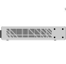
Side Panels
Ventilation Holes
WARNING: FAILURE TO PROVIDE PROPER VENTILATION MAY CAUSE FIRE HAZARD. KEEP AT LEAST 20 MM OF CLEARANCE NEXT TO THE VENTILATION HOLES FOR ADEQUATE AIRFLOW.
WARNING: The US-8-150W must not be stacked. Do not place it on top of another switch. Do not place anything on top of the US-8-150W.

Hardware Installation
WARNING: To reduce the risk of fire or electric shock, do not expose the switch to rain or moisture.
Shelf Mounting
1.Position the two Mount Brackets as shown below, and attach the brackets using the eight Bracket Screws.
2.Secure the UniFi Switch to the shelf using the four
MountingScrews.

Wall Mounting
1.Position the two Mount Brackets as shown below, and attach the brackets using the eight Bracket Screws.
2.Attach the UniFi Switch to the wall using the four Screw Anchors and four Mounting Screws.
 Loading...